EP0624418B1 - Reibschweissen - Google Patents
Reibschweissen Download PDFInfo
- Publication number
- EP0624418B1 EP0624418B1 EP94303413A EP94303413A EP0624418B1 EP 0624418 B1 EP0624418 B1 EP 0624418B1 EP 94303413 A EP94303413 A EP 94303413A EP 94303413 A EP94303413 A EP 94303413A EP 0624418 B1 EP0624418 B1 EP 0624418B1
- Authority
- EP
- European Patent Office
- Prior art keywords
- component
- force
- clamping means
- weld
- friction
- Prior art date
- Legal status (The legal status is an assumption and is not a legal conclusion. Google has not performed a legal analysis and makes no representation as to the accuracy of the status listed.)
- Expired - Lifetime
Links
- 238000003466 welding Methods 0.000 title claims description 36
- 238000000034 method Methods 0.000 claims description 12
- 239000000463 material Substances 0.000 description 3
- 238000004519 manufacturing process Methods 0.000 description 2
- 238000010008 shearing Methods 0.000 description 2
- 238000006934 Blum Aziridine synthesis reaction Methods 0.000 description 1
- 230000000712 assembly Effects 0.000 description 1
- 238000000429 assembly Methods 0.000 description 1
- 230000009286 beneficial effect Effects 0.000 description 1
- 238000006243 chemical reaction Methods 0.000 description 1
- 238000010276 construction Methods 0.000 description 1
- 238000010438 heat treatment Methods 0.000 description 1
- 239000012535 impurity Substances 0.000 description 1
- 238000003780 insertion Methods 0.000 description 1
- 230000037431 insertion Effects 0.000 description 1
- 238000002844 melting Methods 0.000 description 1
- 230000008018 melting Effects 0.000 description 1
- 239000002184 metal Substances 0.000 description 1
Images

Classifications
-
- B—PERFORMING OPERATIONS; TRANSPORTING
- B23—MACHINE TOOLS; METAL-WORKING NOT OTHERWISE PROVIDED FOR
- B23K—SOLDERING OR UNSOLDERING; WELDING; CLADDING OR PLATING BY SOLDERING OR WELDING; CUTTING BY APPLYING HEAT LOCALLY, e.g. FLAME CUTTING; WORKING BY LASER BEAM
- B23K20/00—Non-electric welding by applying impact or other pressure, with or without the application of heat, e.g. cladding or plating
- B23K20/12—Non-electric welding by applying impact or other pressure, with or without the application of heat, e.g. cladding or plating the heat being generated by friction; Friction welding
- B23K20/1205—Non-electric welding by applying impact or other pressure, with or without the application of heat, e.g. cladding or plating the heat being generated by friction; Friction welding using translation movement
-
- B—PERFORMING OPERATIONS; TRANSPORTING
- B23—MACHINE TOOLS; METAL-WORKING NOT OTHERWISE PROVIDED FOR
- B23K—SOLDERING OR UNSOLDERING; WELDING; CLADDING OR PLATING BY SOLDERING OR WELDING; CUTTING BY APPLYING HEAT LOCALLY, e.g. FLAME CUTTING; WORKING BY LASER BEAM
- B23K2101/00—Articles made by soldering, welding or cutting
- B23K2101/001—Turbines
Definitions
- This invention relates to friction welding.
- Compressor assemblies may comprise a blisk (blades plus integral disc), or a blum (blades plus integral drum) which is effectively several blisks joined together.
- Holding a blade, or other component, to be friction welded poses problems.
- the component is mounted in sets of adjustable collet jaws which are adjusted, that is tightened, to exert a force gripping the component in the jaws.
- This known way of gripping a component is exemplified by the prior art disclosures cited in the search report.
- the rod 162 is gripped by jaws 160 with a force which is increased by the action of camming surfaces provided by a conical head portion of the collet 158 carrying the gripping jaws.
- the conical portion causes the gripping force to tighten.
- GB Patent No 1,488,887 discloses an arrangement for holding a tubular weld component of the kind commonly found in machine tools, such as lathes.
- the component 10 is loaded axially into an annular chuck 22 which carries a plurality of radially adjustable jaws 24. Again, in order to load the component 10 into the chuck 22 the jaws 24 must be retracted.
- a method of holding a first component in a friction clamping means during a friction welding operation in which the first component is forced against a second component with a weld-pressure generating force and relative cyclical motion is produced between the two components to generate welding heat
- the friction clamping means has a portion formed with a component receiving aperture defined by the internal sidewalls of a cavity into which the component must be pressed with a substantial force to generate a frictional clamping force gripping a part of the component with a force at least equal to or greater than the weld-pressure generating force, whereby the component is held solely by frictional engagement of the side walls of the aperture with opposite sides of the part of the component.
- the frictional forces act in the generally opposite direction to the weld-pressure generating direction.
- the frictional gripping force on the component by component holding means is at least as great as the weld-pressure generating force.
- a method of friction welding in which a first component is forced against a second component with a weld-pressure generating force while relative cyclical motion is produced between the two components to generate welding heat, and the first component is held in a friction clamping means characterised in that the friction clamping means has an end face formed with a component receiving aperture defined by the internal sidewalls of a cavity into which the component must be pressed with a substantial force to generate a frictional clamping force gripping a part of the component with a force at least equal to or greater than the weld pressure generating force, whereby the component is held solely by frictional engagement of the side walls of the aperture with opposite sides of the part of the component.
- the method also includes removing weld flash which may be generated between the component and the workpiece by causing the friction clamping means and the workpiece (or weld flash) to move relatively towards each other, so that the friction clamping means moves in use relative to the component in a weld-flash removal operation following a welding operation and removes the weld-flash as it passes the weld.
- weld flash may be generated between the component and the workpiece by causing the friction clamping means and the workpiece (or weld flash) to move relatively towards each other, so that the friction clamping means moves in use relative to the component in a weld-flash removal operation following a welding operation and removes the weld-flash as it passes the weld.
- friction clamping means for holding a first component during a friction welding operation in which the first component is forced against a second component with a weld-pressure generating force and relative cyclical motion is produced between the two components to generate welding heat, comprising clamping means for exerting a frictional clamping force on the component characterised in that the friction clamping means has a portion formed with a component receiving aperture defined by the internal sidewalls of a cavity into which the component must be pressed with a substantial force to generate a frictional clamping force gripping a part the component with a force at least equal to or greater than the weld-pressure generating force, whereby the component is held solely by frictional engagement of the side walls of the aperture with opposite sides of the part of the component.
- the clamping force of the friction clamping means is preferably not reduced substantially when the friction clamping means is pulled off the component.
- the friction clamping means and the workpiece are moved apart along a line parallel to the weld pressure direction after flash removal.
- the component is a press fit in the friction clamping means and the tightness of fit generates the frictional relative movement resisting force.
- the above inventions are especially, but not exclusively, suited to welding blades onto a compressor disc or drums, or blades to turbines.
- FIG. 1 is a section through the blade blank on the line AA of Figure 2
- Figure 2 is an end view of the blank in the direction of arrow B in Figure 1
- Figure 3 is a perspective view.
- Figure 2 shows clearly the aerofoil section 4 of the blade, and the slightly thicker cross-section of the root portion 6.
- the root of the blade is machined to the desired finished shape, preferably by broaching, after it has been welded to a disc or drum.
- the root portion 6 of the unwelded blade 2 which is welded to the drum may comprise in cross-section a rectangular shank 6.
- Figure 4 is an end view of a blade loaded into a blade holder, generally indicated at 8, corresponding to the view of Figure 2 of the blade alone.
- Figure 5 is a view in the direction of arrow D in Figure 4 and shows details of a blade 2 held in the component holder 8.
- the component holder 8 comprises essentially a hollow box, tube or cassette open at one end. At said one end the sides of the holder define an aperture 10 into which the blade 2 is pressed.
- the shape and dimensions of aperture 10 correspond to the plan shape and dimensions of root shank 6 such that a substantial force is necessary to press the blade into the cassette 8. Further reference will be made to this operation below with reference to Figure 7.
- the side walls surrounding the aperture 10 are preferably parallel and engage the flanks of the component with a substantial frictional force.
- the flanks of the component are also parallel. Normally, it is expected, the component will be formed with a thicker root portion to accommodate the parallel blade root flanks.
- the blade shank 6 must be a force-fit in the aperture 10 so that a substantial force has to be exerted, in excess of the forces generated during the friction welding operation, in order to insert the blade root 6 into the holder 8 and to ensure it is held in place by friction throughout the welding operation.
- the frictional force by which the blade is held in place in the holder must provide a residual holding force even when other forces acting on the holder/blade interface reach maximum during the welding phase.
- the component holder or cassette 8 comprises a rectangular base portion 12 from one face of which there is an upstanding sleeve, tube or box portion 14 into the hollow interior 16 of which the blade blank 2 is received.
- the internal cavity 16 of the cassette 8, as shown by a dashed line in Figure 5 is blind and, therefore, does not extend through base portion 12. This is not absolutely necessary, however, and the cavity 16 may extend through base 12 so that the cassette is open at both ends, this may ease manufacture of the cassette.
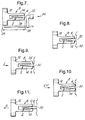
- the internal surfaces of the cassette, which define internal cavity 16, may be spaced apart away from the aperture 10 as is shown in Figures 7 to 11. In this latter case the side walls of aperture 10 which engage the blade shank extend parallel from the cassette end face into the interior for a depth sufficient to generate the desired frictional clamping force.
- the end face 18 of the cassette 8 may be formed flat or, as shown in Figures 4 to 6, it may be formed with a raised shearing edge 20 extending laterally across the end face on either side of aperture 10.
- the clamping means of the present invention is useful in, but not exclusive to, the angular reciprocatory welding method and apparatus described in co-pending patent application nos GB 9309824.2 and GB 9309865.5 (Agents Ref:AST 1265 & AST 1266). Relative angular friction movement between the drum and the blade may be in the direction of arrow 19 or arrow 21, or indeed any direction in the interface plane.
- the component holding means 8 has an internal chamber which is adapted to receive in use a component to be welded to a workpiece. Thus the component extends in use almost wholly into the chamber.
- the holder 8 surrounds the blade 2 which is expected to be close to near finished shape and therefore should be shielded against direct forces such as end loads during welding. In this arrangement, as described above, all loads are applied through the faces of the aperture 10 to the shank 6 of the blade. Thus, the airfoil portion 4 of the blade is free of external forces during welding. All welding forces are exerted on the blade shank 6 through the side walls of the aperture 10 which engage the sides of the root shank. The portion of the root which will form the weld joint extends beyond the end face 18 of the holder 8.
- the first component is urged against another component with a weld-pressure generating force while relative friction generating cyclical motion occurs between the two components to generate welding heat, and the component is held using frictional forces only.
- the frictional holding forces act generally in the opposite direction to the weld-pressure generating force.
- the frictional holding or gripping force exerted on the component by the component holding means is at least as great as the weld-pressure generating force so that there is always a residual gripping force acting on the blade shank.
- the tightness of fit generates the frictional holding force which resists relative movement of the holding means and held component.
- the weld generating force is increased to maximum a quantity of material form the weld zone is inevitably upset. This is generally considered beneficial since the expelled material is from the interface surfaces and contains impurities, such as oxides, which tend to reduce weld strength.
- the first stage of the operation comprises loading a blade blank 2 (component) into a holder or cassette 8. This is carried out using an hydraulic press tool 22 in the direction of arrow 24.
- the press tool 22 is fitted with a depth gauge 26 set to a predetermined distance 28.
- the blade 2 is then pressed into the aperture 10 in holder 8 until the tip of gauge 26 reaches a datum surface 29 flush with the bottom face of the base portion 12 of the holder.
- the overall height of the holder 8 and the portion of the blade root 6 protruding above end face 18 is always equal to the predetermined distance 28.
- the loaded cassette is subsequently positioned in a friction welding machine and presented to a stub 30 on the periphery of a disc 32 ready for a welding operation, Figure 8.
- the welding machine angularly reciprocates disc 30 while a weld-generating force arrow E is applied to holder 8, as described in co-pending application nos GB 9309824.2 and GB 9309865.5 (Agents Ref: AST 1265A and AST 1266A).
- the frictional relative movement resisting force between the clamping means and the component is preferably not reduced, or not reduced substantially, in the flash removal operation.
- the whole of the frictional gripping force is generated by the construction and resilience of the holding means.
- the clamping force of the friction clamping means is preferably not reduced substantially when the friction clamping means is pulled off the component.
- the friction clamping means and the workpiece are moved apart along a line parallel to the weld pressure direction after flash removal.
- the present invention is especially, but not exclusively, suited to welding blades onto a compressor disc or drums, or blades to turbines. That is, the component loaded into the cassette holder need not be a blade nor the component to which it is welded need to be a disc. In the case of blisks and blums, however, the invention may be used in original manufacture or repair.
Landscapes
- Engineering & Computer Science (AREA)
- Mechanical Engineering (AREA)
- Pressure Welding/Diffusion-Bonding (AREA)
Claims (10)
- Verfahren zum Halten eines ersten Bauteils (2) in einer Reibschluß-Klemmvorrichtung (8) während eines Reibschweißvorgangs, bei welchem das erste Bauteil (2) gegen ein zweites Bauteil (30) mit einer schweißdruckerzeugenden Kraft (E) gedrückt und eine zyklische Relativbewegung zwischen den beiden Bauteilen (2, 30) zur Erzeugung von Schweißwärme erzeugt wird, dadurch gekennzeichnet, daß die Reibschluß-Klemmvorrichtung (8) ein Teil (18) aufweist, das mit einer Bauteilaufnahmeöffnung (10) ausgebildet ist, die durch die inneren Seitenwände eines Hohlraums (16) umschrieben ist, in welche das Bauteil (2) mit beträchtlicher Kraft eingedrückt werden muß, um eine reibschlüssige Klemmkraft zu erzeugen, welche einen Teil (6) des Bauteils (2) mit einer Kraft ergreift, die mindestens gleich groß oder größer als die schweißdruckerzeugende Kraft (E) ist, derart, daß das Bauteil (2) ausschließlich durch reibschlüssige Anlage der Seitenwände der Öffnung (10) mit gegenüberliegenden Seitenflächen jenes Teils (6) des Bauteils (2) gehalten wird.
- Verfahren nach Anspruch 1, dadurch gekennzeichnet, daß die Klemmkraft der Reibschluß-Klemmvorrichtung (8) nicht wesentlich verringert wird, wenn die Reibschluß-Klemmvorrichtung (8) von dem Bauteil abgezogen wird.
- Verfahren zum Reibschweißen, bei welchem ein erstes Bauteil (2) mit einer schweißdruckerzeugenden Kraft (E) gegen ein zweites Bauteil (30) gedrückt wird, während eine zyklische Relativbewegung zwischen den beiden Bauteilen (2, 30) zur Erzeugung von Schweißwärme erzeugt wird, und wobei das erste Bauteil (2) in einer Reibschluß-Klemmvorrichtung (8) gehalten wird, dadurch gekennzeichnet, daß die Reibschluß-Klemmvorrichtung (8) eine Stirnfläche (18) aufweist, die mit einer Bauteilaufnahmeöffnung (10) ausgebildet ist, die durch die inneren Seitenwände eines Hohlraums (16) gebildet ist, in welche das Bauteil (2) mit einer beträchtlichen Kraft eingedrückt werden muß, um eine reibschlüssige Klemmkraft zu erzeugen, die einen Teil (6) des Bauteils (2) mit einer Kraft ergreift, die mindestens gleich groß oder größer als die schweißdruckerzeugende Kraft (E) ist, derart, daß das Bauteil (2) ausschließlich durch reibschlüssige Anlage der Seitenwände der Öffnung (10) an gegenüberliegenden Seitenflächen jenes Teils (6) des Bauteils (2) gehalten wird.
- Verfahren nach Anspruch 3, dadurch gekennzeichnet, daß die durch die Reibschluß-Klemmvorrichtung (8) ausgeübte Klemmkraft vorzugsweise nicht wesentlich verringert wird, wenn die Reibschluß-Klemmvorrichtung (8) von dem Bauteil abgezogen wird.
- Verfahren nach Anspruch 3 oder 4, das außerdem das Entfernen von beim Schweißen zwischen dem Bauteil (2) und dem Werkstück verdrängtem Material umfaßt, in dem die Reibschluß-Klemmgvorrichtung (8) und das Bauteil (2) relativ zueinander derart bewegt werden, daß die Reibschluß-Klemmvorrichtung (8) sich in einem dem Schweißvorgang folgenden Verdrängungsmaterial-Entfernungsvorgang relativ zum Bauteil (2) bewegt und beim Passieren der Schweißnaht das Verdrängungsmaterial entfernt.
- Verfahren nach Anspruch 5, wobei die Reibschluß-Klemmvorrichtung (8) in Richtung der Schweißdruckkraft (E) vorwärts bewegt wird, um das Verdrängungsmaterial zu entfernen.
- Verfahren nach Anspruch 5 oder 6, dadurch gekennzeichnet, daß die einer Relativbewegung entgegenwirkende Reibschlußkraft zwischen der Klemmvorrichtung (8) und dem Bauteil (2) bei dem Verdrängungsmaterial-Entfernungsvorgang nicht wesentlich verringert wird.
- Reibschluß-Klemmvorrichtung zum Halten eines ersten Bauteils (2) während eines Reibschweißvorgangs, bei welchem das erste Bauteil (8) gegen ein zweites Bauteil (30) mit einer schweißdruckerzeugenden Kraft (E) gedrückt wird und eine zyklische Relativbewegung zwischen den beiden Bauteilen (2, 30) zur Erzeugung von Schweißwärme erzeugt wird, mit Klemmmitteln (8) zum Ausüben einer reibschlüssigen Klemmkraft auf das Bauteil (2), dadurch gekennzeichnet, daß die Reibschluß-Klemmvorrichtung (8) ein Teil (18) aufweist, das mit einer Bauteilaufnahmeöffnung (10) ausgebildet ist, die durch die inneren Seitenwände eines Hohlraums (16) gebildet ist, in welche das Bauteil (2) mit einer beträchtlichen Kraft eingedrückt werden muß, um eine reibschlüssige Klemmkraft zu erzeugen, die einen Teil (6) des Bauteils (2) mit einer Kraft ergreift, die mindestens gleich groß oder größer als die schweißdruckerzeugende Kraft (E) ist, derart, daß das Bauteil (2) ausschließlich durch reibschlüssige Anlage der Seitenwände der Öffnung (10) an gegenüberliegenden Seitenflächen jenes Teils (6) des Bauteils (2) gehalten wird.
- Reibschluß-Klemmvorrichtung nach Anspruch 8, wobei die Seitenwände der Öffnung (10), die an gegenüberliegenden Seitenflächen des Bauteils (2) anliegen, derart voneinander beabstandet sind, daß das Bauteil (2) mit einem Preßsitz in der Reibschluß-Klemmvorrichtung sitzt.
- Reibschluß-Klemmvorrichtung nach Anspruch 8 oder 9, wobei die Stirnfläche (18) der Klemmvorrichtung mit einem Element (20) zum Erleichtern der Entfernung von Schweißverdrängungsmaterial versehen ist.
Applications Claiming Priority (2)
| Application Number | Priority Date | Filing Date | Title |
|---|---|---|---|
| GB9309822 | 1993-05-13 | ||
| GB939309822A GB9309822D0 (en) | 1993-05-13 | 1993-05-13 | Improvements relating to friction welding |
Publications (3)
| Publication Number | Publication Date |
|---|---|
| EP0624418A2 EP0624418A2 (de) | 1994-11-17 |
| EP0624418A3 EP0624418A3 (de) | 1995-07-26 |
| EP0624418B1 true EP0624418B1 (de) | 1997-07-09 |
Family
ID=10735370
Family Applications (1)
| Application Number | Title | Priority Date | Filing Date |
|---|---|---|---|
| EP94303413A Expired - Lifetime EP0624418B1 (de) | 1993-05-13 | 1994-05-12 | Reibschweissen |
Country Status (4)
| Country | Link |
|---|---|
| US (1) | US5492581A (de) |
| EP (1) | EP0624418B1 (de) |
| DE (1) | DE69404084T2 (de) |
| GB (2) | GB9309822D0 (de) |
Families Citing this family (27)
| Publication number | Priority date | Publication date | Assignee | Title |
|---|---|---|---|---|
| FR2716397B1 (fr) * | 1994-02-23 | 1996-04-05 | Snecma | Procédé de soudage de deux parties d'aube. |
| GB2296885B (en) * | 1994-12-23 | 1998-02-04 | Rolls Royce Plc | Friction welding tooling |
| DE69502467T2 (de) * | 1994-12-23 | 1998-12-24 | Rolls-Royce Plc, London | Reibschweisswerkzeug |
| GB2296212B (en) * | 1994-12-23 | 1998-02-04 | Rolls Royce Plc | Friction welding tooling |
| US5813593A (en) * | 1996-11-15 | 1998-09-29 | General Electric Company | Translational friction welding apparatus and method |
| US5865364A (en) * | 1996-12-24 | 1999-02-02 | United Technologies Corporation | Process for linear friction welding |
| JP3897391B2 (ja) * | 1997-03-25 | 2007-03-22 | 昭和電工株式会社 | 金属製接合部材の摩擦撹拌接合法 |
| US6022194A (en) * | 1997-06-18 | 2000-02-08 | Siemens Westinghouse Power Corporation | Linear priction welding of steeples and device thereof |
| JP4048290B2 (ja) * | 1997-11-19 | 2008-02-20 | 株式会社豊田自動織機 | 摩擦圧接機のばり取り装置 |
| US6244495B1 (en) * | 1998-11-06 | 2001-06-12 | United Technologies Corporation | Gripper |
| US6779708B2 (en) * | 2002-12-13 | 2004-08-24 | The Boeing Company | Joining structural members by friction welding |
| US7080434B2 (en) * | 2003-06-06 | 2006-07-25 | General Electric Company | Fixture having integrated datum locators |
| GB0316158D0 (en) * | 2003-07-10 | 2003-08-13 | Rolls Royce Plc | Method of making aerofoil blisks |
| FR2859933B1 (fr) * | 2003-09-19 | 2006-02-10 | Snecma Moteurs | Procede de fabrication ou de reparation d'un disque aubage monobloc |
| DE502006000502D1 (de) * | 2005-03-03 | 2008-05-08 | Mtu Aero Engines Gmbh | Verfahren zum Reibschweissfügen von einer Laufschaufel an einen Rotorgrundkörper mit Bewegung eines zwischen der Laufschaufel und dem Rotorgrundkörper angeordneten Fügeteils |
| US20090185908A1 (en) * | 2008-01-21 | 2009-07-23 | Honeywell International, Inc. | Linear friction welded blisk and method of fabrication |
| FR2944723B1 (fr) | 2009-04-27 | 2011-04-22 | Eurocopter France | Outillage pour le maintien de pieces metalliques de faible epaisseur composant une structure creuse, en vue de leur soudage l'une a l'autre par friction |
| US8479391B2 (en) | 2009-12-16 | 2013-07-09 | United Technologies Corporation | Consumable collar for linear friction welding of blade replacement for damaged integrally bladed rotors |
| US9694440B2 (en) | 2010-10-22 | 2017-07-04 | United Technologies Corporation | Support collar geometry for linear friction welding |
| GB2514086B (en) * | 2013-03-11 | 2017-12-06 | Kuka Systems Uk Ltd | Linear friction welding |
| US9981584B2 (en) | 2014-10-29 | 2018-05-29 | Toyota Motor Engineering & Manufacturing North America, Inc. | Method of reinforcing a seatback frame of a seat assembly |
| DE102016224386A1 (de) * | 2016-12-07 | 2018-06-07 | MTU Aero Engines AG | Verfahren zum herstellen einer schaufel für eine strömungsmaschine |
| GB2560001B (en) * | 2017-02-24 | 2019-07-17 | Rolls Royce Plc | A weld stub arrangement and a method of using the arrangement to make an article |
| CN109175672B (zh) * | 2018-11-05 | 2020-08-04 | 中国航空制造技术研究院 | 线性摩擦焊接过程中飞边变形控制装置及方法 |
| CN109262132B (zh) * | 2018-11-05 | 2020-08-04 | 中国航空制造技术研究院 | 一种整体叶盘摆动摩擦焊接设备及方法 |
| CN113770654B (zh) * | 2020-05-14 | 2023-06-02 | 中国兵器工业第五九研究所 | 一种多叶片构件的焊接方法 |
| CN114043068B (zh) * | 2021-10-22 | 2023-02-28 | 中国航空制造技术研究院 | 一种线性摩擦焊接头飞边成形控制方法 |
Family Cites Families (14)
| Publication number | Priority date | Publication date | Assignee | Title |
|---|---|---|---|---|
| US3499068A (en) * | 1966-04-20 | 1970-03-03 | Brown Machine Co Of Michigan | Methods and apparatus for making containers |
| US3627189A (en) * | 1968-11-25 | 1971-12-14 | Gen Electric | Friction welder |
| AT302789B (de) * | 1970-04-07 | 1972-10-25 | Evg Entwicklung Verwert Ges | Verfahren und Maschine zum Herstellen von geschweißten Gittern nach der Reibschweißmethode |
| US3699639A (en) * | 1970-10-27 | 1972-10-24 | Gen Motors Corp | Friction welding methods |
| US3896986A (en) * | 1971-01-25 | 1975-07-29 | Gkn Sankey Ltd | Methods of and apparatus for production of wheels and other articles by friction or other welding |
| FR2218156B2 (de) * | 1973-02-21 | 1976-09-10 | Naphtachimie Sa | |
| GB1456855A (en) * | 1973-03-09 | 1976-12-01 | Dunlop Ltd | Method of producing rubber-plastics composites |
| US3860468A (en) * | 1973-04-10 | 1975-01-14 | Du Pont | Angular welding process and apparatus |
| GB1488887A (en) * | 1975-10-21 | 1977-10-12 | Clarke Chapman Ltd | Method and apparatus for friction welding |
| US4239575A (en) * | 1978-10-26 | 1980-12-16 | William C. Heller, Jr. | Method and apparatus for movement of heated thermoplastic elements for shear-fusion bonding of such thermoplastic elements |
| GB2161732B (en) * | 1984-07-20 | 1987-10-07 | Welding Inst | Chuck assembly |
| GB8822235D0 (en) * | 1988-09-21 | 1988-10-26 | Allwood Searle & Timney | Friction welding |
| GB2243097B (en) * | 1990-04-18 | 1994-01-26 | Pirelli General Plc | Manufacture of metal tubes |
| GB9011605D0 (en) * | 1990-05-24 | 1990-07-11 | Rolls Royce Plc | Friction bonding |
-
1993
- 1993-05-13 GB GB939309822A patent/GB9309822D0/en active Pending
-
1994
- 1994-05-12 DE DE69404084T patent/DE69404084T2/de not_active Expired - Lifetime
- 1994-05-12 GB GB9409457A patent/GB2277897B/en not_active Expired - Fee Related
- 1994-05-12 EP EP94303413A patent/EP0624418B1/de not_active Expired - Lifetime
- 1994-05-13 US US08/242,459 patent/US5492581A/en not_active Expired - Lifetime
Also Published As
| Publication number | Publication date |
|---|---|
| GB9309822D0 (en) | 1993-06-23 |
| DE69404084D1 (de) | 1997-08-14 |
| US5492581A (en) | 1996-02-20 |
| GB2277897B (en) | 1995-11-22 |
| EP0624418A2 (de) | 1994-11-17 |
| EP0624418A3 (de) | 1995-07-26 |
| GB9409457D0 (en) | 1994-06-29 |
| GB2277897A (en) | 1994-11-16 |
| DE69404084T2 (de) | 1998-02-12 |
Similar Documents
| Publication | Publication Date | Title |
|---|---|---|
| EP0624418B1 (de) | Reibschweissen | |
| EP0404531B1 (de) | Reibverbindungsgerät | |
| US5971252A (en) | Friction stir welding process to repair voids in aluminum alloys | |
| US3853258A (en) | Flash removal apparatus for a friction welding operation | |
| JP3051057B2 (ja) | 2つの構成部材を反復可能に固定結合する装置と方法 | |
| US3609854A (en) | Method of friction welding | |
| US20120181324A1 (en) | Joining method and joining tool | |
| CA3042636C (en) | Linear friction welding apparatus and method | |
| EP0330341A1 (de) | Nietwerkzeug und Verfahren zum Einpressen von Nieten | |
| EP0458630B1 (de) | Reibschweissung | |
| US5188275A (en) | Friction bonding clamp for a rotor blade | |
| US8851357B2 (en) | Apparatus and method for removing weld flash | |
| EP1000697B1 (de) | Greifer | |
| US6108890A (en) | Method of removing punch rivets set into a workpiece | |
| US3597832A (en) | Inertia welding of steel to aluminum | |
| CN100513046C (zh) | 搅拌摩擦焊方法及夹具、具有搅拌摩擦焊接头的部件 | |
| US3719983A (en) | Internal flash removal method | |
| JPH1110364A (ja) | 摩擦溶接方法 | |
| JPH07290247A (ja) | アーク溶接用コンタクトチップ及びその製造方法 | |
| JPH08126914A (ja) | 金属パイプ端面のバリ取装置 | |
| JP6794945B2 (ja) | 接合方法 | |
| JP6747365B2 (ja) | 接合方法 | |
| JPH0833983A (ja) | アーク溶接用コンタクトチップ及びその製造方法 | |
| JPH07195202A (ja) | 摩擦圧接機用の内バリ切削装置 | |
| JP2003236670A (ja) | バリ取り方法及び装置 |
Legal Events
| Date | Code | Title | Description |
|---|---|---|---|
| PUAI | Public reference made under article 153(3) epc to a published international application that has entered the european phase |
Free format text: ORIGINAL CODE: 0009012 |
|
| AK | Designated contracting states |
Kind code of ref document: A2 Designated state(s): DE FR GB IT |
|
| PUAL | Search report despatched |
Free format text: ORIGINAL CODE: 0009013 |
|
| 17P | Request for examination filed |
Effective date: 19950412 |
|
| AK | Designated contracting states |
Kind code of ref document: A3 Designated state(s): DE FR GB IT |
|
| 17Q | First examination report despatched |
Effective date: 19960618 |
|
| GRAG | Despatch of communication of intention to grant |
Free format text: ORIGINAL CODE: EPIDOS AGRA |
|
| GRAH | Despatch of communication of intention to grant a patent |
Free format text: ORIGINAL CODE: EPIDOS IGRA |
|
| GRAH | Despatch of communication of intention to grant a patent |
Free format text: ORIGINAL CODE: EPIDOS IGRA |
|
| GRAA | (expected) grant |
Free format text: ORIGINAL CODE: 0009210 |
|
| AK | Designated contracting states |
Kind code of ref document: B1 Designated state(s): DE FR GB IT |
|
| PG25 | Lapsed in a contracting state [announced via postgrant information from national office to epo] |
Ref country code: IT Free format text: LAPSE BECAUSE OF FAILURE TO SUBMIT A TRANSLATION OF THE DESCRIPTION OR TO PAY THE FEE WITHIN THE PRESCRIBED TIME-LIMIT;WARNING: LAPSES OF ITALIAN PATENTS WITH EFFECTIVE DATE BEFORE 2007 MAY HAVE OCCURRED AT ANY TIME BEFORE 2007. THE CORRECT EFFECTIVE DATE MAY BE DIFFERENT FROM THE ONE RECORDED. Effective date: 19970709 |
|
| REF | Corresponds to: |
Ref document number: 69404084 Country of ref document: DE Date of ref document: 19970814 |
|
| ET | Fr: translation filed | ||
| PLBE | No opposition filed within time limit |
Free format text: ORIGINAL CODE: 0009261 |
|
| STAA | Information on the status of an ep patent application or granted ep patent |
Free format text: STATUS: NO OPPOSITION FILED WITHIN TIME LIMIT |
|
| 26N | No opposition filed | ||
| REG | Reference to a national code |
Ref country code: GB Ref legal event code: IF02 |
|
| PGFP | Annual fee paid to national office [announced via postgrant information from national office to epo] |
Ref country code: FR Payment date: 20110607 Year of fee payment: 18 |
|
| PGFP | Annual fee paid to national office [announced via postgrant information from national office to epo] |
Ref country code: GB Payment date: 20110520 Year of fee payment: 18 |
|
| PGFP | Annual fee paid to national office [announced via postgrant information from national office to epo] |
Ref country code: DE Payment date: 20110520 Year of fee payment: 18 |
|
| GBPC | Gb: european patent ceased through non-payment of renewal fee |
Effective date: 20120512 |
|
| REG | Reference to a national code |
Ref country code: FR Ref legal event code: ST Effective date: 20130131 |
|
| REG | Reference to a national code |
Ref country code: DE Ref legal event code: R119 Ref document number: 69404084 Country of ref document: DE Effective date: 20121201 |
|
| PG25 | Lapsed in a contracting state [announced via postgrant information from national office to epo] |
Ref country code: FR Free format text: LAPSE BECAUSE OF NON-PAYMENT OF DUE FEES Effective date: 20120531 Ref country code: GB Free format text: LAPSE BECAUSE OF NON-PAYMENT OF DUE FEES Effective date: 20120512 |
|
| PG25 | Lapsed in a contracting state [announced via postgrant information from national office to epo] |
Ref country code: DE Free format text: LAPSE BECAUSE OF NON-PAYMENT OF DUE FEES Effective date: 20121201 |