EP0622509B1 - Furniture hinge - Google Patents
Furniture hinge Download PDFInfo
- Publication number
- EP0622509B1 EP0622509B1 EP93101932A EP93101932A EP0622509B1 EP 0622509 B1 EP0622509 B1 EP 0622509B1 EP 93101932 A EP93101932 A EP 93101932A EP 93101932 A EP93101932 A EP 93101932A EP 0622509 B1 EP0622509 B1 EP 0622509B1
- Authority
- EP
- European Patent Office
- Prior art keywords
- hinge
- cabinet
- fastening plate
- frame element
- tabs
- Prior art date
- Legal status (The legal status is an assumption and is not a legal conclusion. Google has not performed a legal analysis and makes no representation as to the accuracy of the status listed.)
- Expired - Lifetime
Links
Images

Classifications
-
- E—FIXED CONSTRUCTIONS
- E05—LOCKS; KEYS; WINDOW OR DOOR FITTINGS; SAFES
- E05D—HINGES OR SUSPENSION DEVICES FOR DOORS, WINDOWS OR WINGS
- E05D5/00—Construction of single parts, e.g. the parts for attachment
- E05D5/02—Parts for attachment, e.g. flaps
- E05D5/06—Bent flaps
- E05D5/065—Bent flaps specially adapted for cabinets or furniture
-
- E—FIXED CONSTRUCTIONS
- E05—LOCKS; KEYS; WINDOW OR DOOR FITTINGS; SAFES
- E05D—HINGES OR SUSPENSION DEVICES FOR DOORS, WINDOWS OR WINGS
- E05D5/00—Construction of single parts, e.g. the parts for attachment
- E05D5/02—Parts for attachment, e.g. flaps
- E05D5/08—Parts for attachment, e.g. flaps of cylindrical shape
-
- E—FIXED CONSTRUCTIONS
- E05—LOCKS; KEYS; WINDOW OR DOOR FITTINGS; SAFES
- E05Y—INDEXING SCHEME RELATING TO HINGES OR OTHER SUSPENSION DEVICES FOR DOORS, WINDOWS OR WINGS AND DEVICES FOR MOVING WINGS INTO OPEN OR CLOSED POSITION, CHECKS FOR WINGS AND WING FITTINGS NOT OTHERWISE PROVIDED FOR, CONCERNED WITH THE FUNCTIONING OF THE WING
- E05Y2900/00—Application of doors, windows, wings or fittings thereof
- E05Y2900/20—Application of doors, windows, wings or fittings thereof for furnitures, e.g. cabinets
Definitions
- the invention relates to a hinge for the pivotable articulation of a door leaf on a cabinet body according to the preamble of claim 1.
- a single-joint hinge is known from US Pat. No. 2,973,547, which is held on the body side by means of a fastening plate that can be screwed onto the free end face of the projecting frame element, the width of which is approximately equal to the free end face of the frame element dimensioned mounting plate is an integral part of the hinge arm itself.
- the fastening plate is part of a mounting plate on which the actual hinge support arm forming the body stop part of the hinge is adjustably fastened.
- Both types of hinge have in common that the openings provided in the mounting plate for the mounting screws are designed as elongated holes, so that the door leaf to be hinged to the cabinet body can still be adjusted in height even after installation. By tightening the fastening screws, the fastening plate is then fixed in the new height setting of the door leaf.
- flaps bent at right angles are provided on the front edge of the mounting plate. During assembly, these are pushed into contact with the front of the frame element and thus determine the position of the mounting plate and thus of the hinge arm in the horizontal direction with respect to the cabinet body.
- this position can be temporarily fixed in that a clamping screw is turned by a thread in the folded tab as far as it will go against the frame element.
- Door wings are mounted on the cabinet body, at least in large series production, with hinges pre-assembled on the door wings, in that the door wings with the hinge arm in the open position are suspended from above on the body lying on the rear wall in such a way that the fastening plates of the hinge arm on the free end face of the associated frame element come to rest, whereupon the fastening screws are screwed through the elongated holes in the fastening plates into the frame element.
- the invention has for its object to provide a hinge which enables the pre-assembly of the door leaf on the frame element of the cabinet body by an individual without the risk of the door leaf slipping and possibly resulting therefrom There is damage to the frame element of the cabinet body.
- the height adjustment of the door leaf with loosened fastening screws should still be possible.
- this object is achieved in that at the front and rear edge of the mounting plate at least one substantially right-angled flap on the outside of the cabinet or the inside of the frame element is folded tabs, of which the one or the inside of the cabinet (n) Flap is or are provided with a protruding, tapered or cutting-like, sharpened protrusion toward the inside of the cabinet flat side of the frame element.
- the procedure can then be such that the fastening plate is placed obliquely on the frame element in such a way that the lobes inside the cabinet reach behind the end face on the inside flat side of the frame element, while the front lugs practically on the edge area the face of the frame element. Then, via the door leaf standing in the open position of the hinge and the door leaf stop part, pressure is exerted on the hinge arm, which leads the front tabs over the front edge of the end face of the frame element and pivots the fastening plate towards the end face of the frame element.
- the tapered or sharpened projections on the flaps inside the cabinet dig into the flat side of the frame element inside the cabinet, thereby obtaining a form-fitting mounting of the fastening plate on the frame element, even if no fastening screw has yet been screwed into the frame element through the elongated hole.
- This screwing in of the fastening screw takes place only in a further work step, ie can be done by the same person who pre-assembled the door or - in the case of hinge production - in a next work station.
- This elastic deformation can be achieved in that the material of the hinge and the flap and their dimensions are chosen so that the flaps are resiliently bendable.
- the tabs can also be attached to a section of the fastening plate of the hinge, which in turn is connected to the remaining part of the fastening plate in a resiliently deformable manner. This is possible, for example, by making slots in the mounting plate.
- the protrusion provided on the lobes of the hinge inside the cabinet is provided on the free edge of the lobes facing away from the mounting plate and is sharpened like a blade, and has a segment-shaped boundary.
- the fastening openings in the fastening plates of the hinges holding a door wing on the cabinet body are then formed in a manner known per se as elongated fastening openings running in the longitudinal direction of the end face of the associated frame element in the manner of elongated holes, through which the shafts of the fastening screws are screwed into the frame element.
- the folded tabs provided on the outside edge of the hinge mounting plate are expediently provided with a rounded cross-section in the region of their free end on the side facing the outside flat side of the associated frame element in order to lead the tabs away over the front edge of the end face of the frame element during preassembly allow without the rags damaging the front edge.
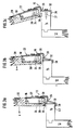
- the hinge shown in FIG. 1, designated in its entirety by 10, serves to link a door leaf (not shown) to a cabinet body, the front side of which is to be closed by the door leaf is narrowed by a projecting frame formed by strip-like frame elements.
- a section of the frame element 14 projecting from a cabinet side wall 12 is shown in dash-dotted lines, on the end wall 16 facing away from the side wall, the hinge is to be fastened on the cabinet side.
- the hinge 10 which is designed as a single-joint hinge in the illustrated case, has a door stop part 22 in the form of an insert pot, which is countersunk in a recess 18 (FIGS. 3a to 3c) in the rear of the door leaf 20, and a bearing pin provided around the inside of the insert pot 24 pivotable body stop part 26.
- the body stop part 26 which is produced in a known manner by stamping and pressing from sheet metal, has a hinge arm 28, at the end of which is located in the insert pot 22, a bearing eye 30 encompassing the bearing pin 24 is rolled on.
- an essentially flat fastening plate 32 is integrally attached, the width of which corresponds approximately to the width of the end face 16 of the frame element 14, and the one as an elongated hole 34 extending parallel to the hinge pivot axis formed by the longitudinal central axis of the bearing pin 24 has designed fastening opening, through which the shaft of a fastening screw 37 (FIG. 3c) can be screwed into the end face 16 of the frame element 14.
- the flaps 36 are rounded off at 42 in the region of their free end on the side associated with the flat outer side of the frame element 14 at 42 in a circular arc.
- the clear distance between the tabs 36 and 38 corresponds - due to the width dimensioning of the mounting plate 32 equal to the width of the end face 16 of the frame element 14 - the distance between the front and the back of the frame element 14, ie in the intended mounting position of the mounting flange 32 on the
- the end face 16, the tabs 36, 38 rest on the front and rear flat side of the frame element 14 and secure the hinge 10 even when the fastening screw 36 is not tightened firmly against horizontal displacement, ie in the direction of the interior of the cabinet or the interior of the cabinet.
- the fastening plate 32 and thus the hinge 10 allow the fastening plate 32 and thus the hinge 10 to be displaced for the purpose of adjusting the height of the door leaf 20 hinged to within the length specified by the elongated hole 34 when the fastening screw 37 is loosened.
- the projection 14, which cuts into the rear of the frame elements 14 from the rear tabs 38, does not hinder an adjustment in the longitudinal direction of the frame, since the curved cutting edge opposes such a displacement only little resistance.
- the tabs 38 with the projections 40 are resiliently attached to the fastening plate 32, which is achieved in that for the manufacture of the body Stop part 26 is a metal sheet hardenable by heat treatment is used, which is thus provided with the required spring-elastic property of the tabs 38 and possibly 36 after completion in the stamping and pressing process by a heat treatment.
- the resistance that the flaps 38 oppose to an elastic deformation is chosen by the choice of appropriate dimensions of the flaps themselves and the indicated arcuate transition region so that the flaps 38 and 36 can spring open during assembly, but the force required for this is is so large that the projections 40 dig into the inner surface of the frame element 14 in any case.
- FIG. 2 illustrates such a configuration of a body stop part that is otherwise unchanged compared to the body stop part 26 according to FIG. 1.
- the tabs 38 on the inside of the cabinet are attached to areas 32a of the fastening plate 32, which in turn are designed to be resiliently deformable with respect to the actual fastening plate 32 by slots 44 made from the transverse edges.
- FIGS. 3a to 3c illustrate the manner in which an individual person assembles a door leaf provided with preassembled hinges 10 on a cabinet body.
- the cabinet body is to be thought of as lying on the back, and the door leaves, together with the hinge arm 30 of the hinge that is in the open position, are brought up to the upward-facing open front side of the cabinet body on a hoist.
- the hinge arm 30 is then guided over the frame element 14 in such a way that the lobes 38 on the inside of the cabinet lie against the inner surface of the frame elements 14 in the inclined position of the fastening plate with the projections 40, as can be seen in FIG.
- the fastening plate is also able to compensate for certain fluctuations in the thickness of the frame element 14.
Abstract
Description
Die Erfindung betrifft ein Scharnier für die verschwenkbare Anlenkung eines Türflügels an einem Schrankkorpus gemäß dem Oberbegriff des Anspruchs 1.The invention relates to a hinge for the pivotable articulation of a door leaf on a cabinet body according to the preamble of claim 1.
Zur schwenkbaren Anlenkung eines Türflügels an einem solchen Rahmen ist aus der US-PS 2,973,547 ein Eingelenk-Scharnier bekannt, welches korpusseitig mittels einer auf der freien Stirnfläche des einspringenden Rahmenelementes aufschraubbaren Befestigungsplatte gehalten wird, wobei die in ihrer Breite etwa gleich der freien Stirnfläche des Rahmenelementes bemessene Befestigungsplatte integraler Teil des Scharnierarms selbst ist.For pivotable articulation of a door leaf on such a frame, a single-joint hinge is known from US Pat. No. 2,973,547, which is held on the body side by means of a fastening plate that can be screwed onto the free end face of the projecting frame element, the width of which is approximately equal to the free end face of the frame element dimensioned mounting plate is an integral part of the hinge arm itself.
Bei anderen Scharnieren ist die Befestigungsplatte Teil einer Montageplatte, auf welcher der eigentliche, den Korpus-Anschlagteil des Scharniers bildende Scharnier-Tragarm verstellbar befestigt ist.In the case of other hinges, the fastening plate is part of a mounting plate on which the actual hinge support arm forming the body stop part of the hinge is adjustably fastened.
Beiden Scharnierarten gemeinsam ist, daß die in der Befestigungsplatte vorgesehenen Öffnungen für die Befestigungsschrauben als Langlöcher ausgebildet werden, so daß der am Schrankkorpus anzulenkende Türflügel auch nach der Montage noch in Höhenrichtung verstellt werden kann. Durch Anziehen der Befestigungsschrauben wird die Befestigungsplatte dann in der eingestellten neuen Höhenlage des Türflügels fixiert.Both types of hinge have in common that the openings provided in the mounting plate for the mounting screws are designed as elongated holes, so that the door leaf to be hinged to the cabinet body can still be adjusted in height even after installation. By tightening the fastening screws, the fastening plate is then fixed in the new height setting of the door leaf.
Zur exakten Festlegung der Befestigungsplatte in bezug auf die horizontale Einstellung des Türflügels am Schrankkorpus sind am vorderen Rand der Befestigungsplatte rechtwinklig umgekantete Lappen vorgesehen. Diese werden bei der Montage bis in Anlage an die Vorderseite des Rahmenelementes geschoben und bestimmen so die Lage der Befestigungsplatte und somit des Scharnierarms in horizontaler Richtung in bezug auf den Schrankkorpus. Bei dem Scharnier gemäß der US-PS 2,973,547 kann diese Lage vorübergehend dadurch fixiert werden, daß eineKlemmschraube durch ein Gewinde in dem umgekanteten Lappen bis zum Anschlag an das Rahmenelement gedreht wird.For exact fixing of the mounting plate with respect to the horizontal adjustment of the door leaf on the cabinet body, flaps bent at right angles are provided on the front edge of the mounting plate. During assembly, these are pushed into contact with the front of the frame element and thus determine the position of the mounting plate and thus of the hinge arm in the horizontal direction with respect to the cabinet body. In the hinge according to US Pat. No. 2,973,547, this position can be temporarily fixed in that a clamping screw is turned by a thread in the folded tab as far as it will go against the frame element.
Die Montage von Türflügeln am Schrankkorpus erfolgt zumindest in der Großserienproduktion mit an den Türflügeln vormontierten Scharnieren, indem die Türflügel mit in der Öffnungsstellung befindlichem Scharnierarm von oben hängend an den auf der Rückwand liegenden Korpus derart herangeführt werden, daß die Befestigungsplatten des Scharnierarms auf der freien Stirnfläche des zugeordneten Rahmenelements zur Auflage kommen, worauf die Befestigungsschrauben durch die Langlöcher in den Befestigungsplatten hindurch in das Rahmenelement eingeschraubt werden. Hierfür sind in der Regel zwei Personen erforderlich, von denen die eine den Türflügel halt und relativ zum Korpus ausrichtet, während die zweite Person die Befestigungsschraube zumindest so weit einschraubt, daß eine erste Halterung des Türflügels am Schrankkorpus erhalten wird.Door wings are mounted on the cabinet body, at least in large series production, with hinges pre-assembled on the door wings, in that the door wings with the hinge arm in the open position are suspended from above on the body lying on the rear wall in such a way that the fastening plates of the hinge arm on the free end face of the associated frame element come to rest, whereupon the fastening screws are screwed through the elongated holes in the fastening plates into the frame element. This usually requires two people, one of whom holds the door leaf and aligns it relative to the body, while the second person screws in the fastening screw at least to the extent that a first mounting of the door leaf on the cabinet body is obtained.
Der Erfindung liegt demgegenüber die Aufgabe zugrunde, ein Scharnier zu schaffen, welches die Vormontage des Türflügels am Rahmenelement des Schrankkorpus durch eine Einzelperson ermöglicht, ohne daß die Gefahr eines Abrutschens des Türflügels sowie einer daraus möglicherweise resultierenden Beschädigung des Rahmenelements des Schrankkorpus besteht. Die Höhenverstellung des Türflügels bei gelockerten Befestigungsschrauben soll aber auch weiterhin möglich sein.In contrast, the invention has for its object to provide a hinge which enables the pre-assembly of the door leaf on the frame element of the cabinet body by an individual without the risk of the door leaf slipping and possibly resulting therefrom There is damage to the frame element of the cabinet body. The height adjustment of the door leaf with loosened fastening screws should still be possible.
Ausgehend von einem Scharnier der eingangs erwähnten Art wird diese Aufgabe erfindungsgemäß dadurch gelöst, daß am vorderen und rückwärtigen Rand der Befestigungsplatte jeweils wenigstens ein im wesentlichen rechtwinklig auf die schrankäußere bzw. schrankinnere Flachseite des Rahmenelements umgekanteter Lappen angeschnitten ist, von denen der bzw. die schrankinnere(n) Lappen mit einem zur schrankinneren Flachseite des Rahmenelements vorspringenden, zugespitzten oder schneidenartigen zugeschärften Vorsprung versehen ist bzw. sind. Für die Vormontage der Befestigungsplatte auf dem Rahmenelement des Schrankkorpus kann dann so verfahren werden, daß die Befestigungsplatte derart schräg auf das Rahmenelement aufgesetzt wird, daß die schrankinneren Lappen hinter die Stirnfläche auf die schrankinnere Flachseite des Rahmenelements greifen, während die vorderen Lappen praktisch im Randbereich auf der Stirnfläche des Rahmenelements aufsitzen. Dann wird über den in der Öffnungsstellung des Scharniers stehenden Türflügel und den Türflügel-Anschlagteil ein Druck auf den Scharnierarm ausgeübt, welcher die vorderen Lappen über die Vorderkante der Stirnfläche des Rahmenelements hinwegführt und die Befestigungsplatte an die Stirnfläche des Rahmenelements heranschwenkt. Dabei graben sich die zugespitzten oder zugeschärften Vorsprünge an den schrankinneren Lappen in die schrankinnere Flachseite des Rahmenelements ein, wodurch eine formschlüssige Halterung der Befestigungsplatte auf dem Rahmenelement erhalten wird, auch wenn noch keine Befestigungsschraube durch das Langloch in das Rahmenelement eingeschraubt ist. D.h. der Türflügel ist also vormontiert, ohne daß eine zweite Person zum Einschrauben der Befestigungsschraube erforderlich ist. Dieses Einschrauben der Befestigungsschraube erfolgt erst in einem weiteren Arbeitsgang, d.h. kann durch die gleiche Person erfolgen, welche die Tür vormontiert hat, oder - bei Bandfertigung - in einer nächstfolgenden Arbeitsstation.Starting from a hinge of the type mentioned at the outset, this object is achieved in that at the front and rear edge of the mounting plate at least one substantially right-angled flap on the outside of the cabinet or the inside of the frame element is folded tabs, of which the one or the inside of the cabinet (n) Flap is or are provided with a protruding, tapered or cutting-like, sharpened protrusion toward the inside of the cabinet flat side of the frame element. For the preassembly of the fastening plate on the frame element of the cabinet body, the procedure can then be such that the fastening plate is placed obliquely on the frame element in such a way that the lobes inside the cabinet reach behind the end face on the inside flat side of the frame element, while the front lugs practically on the edge area the face of the frame element. Then, via the door leaf standing in the open position of the hinge and the door leaf stop part, pressure is exerted on the hinge arm, which leads the front tabs over the front edge of the end face of the frame element and pivots the fastening plate towards the end face of the frame element. The tapered or sharpened projections on the flaps inside the cabinet dig into the flat side of the frame element inside the cabinet, thereby obtaining a form-fitting mounting of the fastening plate on the frame element, even if no fastening screw has yet been screwed into the frame element through the elongated hole. This means that the door leaf is preassembled without the need for a second person to screw in the fastening screw. This screwing in of the fastening screw takes place only in a further work step, ie can be done by the same person who pre-assembled the door or - in the case of hinge production - in a next work station.
Um das Hinwegtreten der am schrankäußeren Rand der Befestigungsplatte des Scharniers vorgesehenen umgekanteten Lappen über die Vorderkante der Stirnfläche des Rahmenelements ohne Beschädigung des Rahmenelements zu ermöglichen, empfiehlt es sich, von den am schrankäußeren und am schrankinneren Rand der Befestigungsplatte des Scharniers vorgesehenen umgekanteten Lappen wenigstens die Lappen eines der Ränder elastisch verformbar an der Befestigungsplatte anzuordnen, so daß der zwischen ihnen bestehende Abstand in einem vorgegebenen Bereich ohne bleibende Verformung veränderbar ist.In order to allow the folded tabs provided on the outside edge of the hinge mounting plate to step away from the front edge of the end face of the frame element without damaging the frame element, it is recommended that at least the tabs provided on the outside edge of the cupboard and the inside edge of the hinge mounting plate be attached to arrange one of the edges elastically deformable on the fastening plate, so that the distance between them can be changed in a predetermined area without permanent deformation.
Diese elastische Verformung kann dadurch erreicht werden, daß das Material des Scharniers und sowie der Lappen und ihre Abmessungen so gewählt werden, daß die Lappen selbst federnd verbiegbar sind.This elastic deformation can be achieved in that the material of the hinge and the flap and their dimensions are chosen so that the flaps are resiliently bendable.
Alternativ können die Lappen auch an einem Teilabschnitt der Befestigungsplatte des Scharniers angesetzt sein, der seinerseits federnd verformbar mit dem restlichen Teil der Befestigungsplatte verbunden ist. Dies ist beispielsweise durch Einbringen von Schlitzen in die Befestigungsplatte möglich.Alternatively, the tabs can also be attached to a section of the fastening plate of the hinge, which in turn is connected to the remaining part of the fastening plate in a resiliently deformable manner. This is possible, for example, by making slots in the mounting plate.
Der an den schrankinneren Lappen des Scharniers vorgesehene Vorsprung ist in vorteilhafter Weiterbildung der Erfindung jeweils am befestigungsplattenabgewandten freien Rand der Lappen vorgesehen und schneidenartig zugeschärft, und hat eine kreissegmentförmige Begrenzung. Beim Verstellen des Türflügels in Höhenrichtung wird dann durch die schneidenartige Zuschärfung des Vorsprungs die von diesem bei der Erstmontage in die Rückseite des Rahmenelements eingegrabene Vertiefung lediglich in Verstellrichtung verlängert, ohne daß der Vorsprung vom Rahmenelement freikommt.In an advantageous development of the invention, the protrusion provided on the lobes of the hinge inside the cabinet is provided on the free edge of the lobes facing away from the mounting plate and is sharpened like a blade, and has a segment-shaped boundary. When the door leaf is adjusted in the vertical direction, the recess that is digged into the rear of the frame element during initial assembly is then only lengthened in the adjustment direction by the cutting-like sharpening of the projection. without the projection coming free from the frame element.
Die Befestigungsöffnungen in den Befestigungsplatten der einen Türflügel am Schrankkorpus halternden Scharniere sind dann in an sich bekannter Weise als in Längsrichtung der Stirnfläche des zugeordneten Rahmenelements verlaufende langgestreckte Befestigungsöffnungen nach Art von Langlöchern ausgebildet, durch welche die Schäfte der Befestigungsschrauben in das Rahmenelement eingeschraubt werden.The fastening openings in the fastening plates of the hinges holding a door wing on the cabinet body are then formed in a manner known per se as elongated fastening openings running in the longitudinal direction of the end face of the associated frame element in the manner of elongated holes, through which the shafts of the fastening screws are screwed into the frame element.
Die am schrankäußeren Rand der Befestigungsplatte des Scharniers vorgesehenen umgekanteten Lappen sind im Bereich ihres freien Endes an der der schrankäußeren Flachseite des zugeordneten Rahmenelements zugewandten Seite zweckmäßig mit einem abgerundeten Querschnitt versehen, um das Hinwegführen der Lappen über die Vorderkante der Stirnfläche des Rahmenelements bei der Vormontage zu ermöglichen, ohne daß die Lappen die Vorderkante beschädigen.The folded tabs provided on the outside edge of the hinge mounting plate are expediently provided with a rounded cross-section in the region of their free end on the side facing the outside flat side of the associated frame element in order to lead the tabs away over the front edge of the end face of the frame element during preassembly allow without the rags damaging the front edge.
Die Erfindung ist in der folgenden Beschreibung eines Ausführungsbeispiels in Verbindung mit der Zeichnung näher erläutert,l und zwar zeigt bzw. zeigen:
- Fig. 1
- eine perspektivische Ansicht eines in der erfindungsgemäßen Weise ausgebildeten Scharniers;
- Fig. 2
- einen im Bereich der Befestigungsplatte gegenüber dem bei dem in Fig. 1 dargestellten Scharnier vorgesehenen Scharnierarm abgewandelten Scharnierarm; und
- Fig. 3a, 3b und 3c
- schematische Seitenansichten verschiedener Stufen der Befestigung eines mit einem erfindungsgemäßen Scharnier versehenen Türflügels am Rahmenelement eines Schrankkorpus.
- Fig. 1
- a perspective view of a hinge formed in the manner according to the invention;
- Fig. 2
- a hinge arm modified in the area of the fastening plate compared to the hinge arm provided in the hinge shown in FIG. 1; and
- 3a, 3b and 3c
- schematic side views of different stages of attachment with an inventive Hinged door leaf on the frame element of a cabinet body.
Das in Fig. 1 gezeigte, in seiner Gesamtheit mit 10 bezeichnete Scharnier dient zur Anlenkung eines - nicht dargestellten - Türflügels an einem Schrankkorpus, dessen durch den Türflügel zu verschließende Vorderseite durch einen von leistenartigen Rahmenelementen gebildeten einspringenden Rahmen verengt ist. In der Zeichnungsfigur ist strichpunktiert ein Abschnitt des von einer Schrank-Seitenwand 12 einspringenden Rahmenelements 14 gezeigt, auf dessen seitenwandabgewandter Stirnfläche 16 das Scharnier korpusseitig befestigt werden soll.The hinge shown in FIG. 1, designated in its entirety by 10, serves to link a door leaf (not shown) to a cabinet body, the front side of which is to be closed by the door leaf is narrowed by a projecting frame formed by strip-like frame elements. In the drawing figure, a section of the
Das im dargestellten Fall als Eingelenk-Scharnier ausgebildete Scharnier 10 weist einen versenkt in einer Aussparung 18 (Fig. 3a bis 3c) in der Rückseite des Türflügels 20 montierbaren Tür-Anschlagteil 22 in Form eines Einsetztopfs und einen um einen im Innern des Einsetztopfs vorgesehenen Lagerstift 24 verschwenkbaren Korpus-Anschlagteil 26 auf.The
Der in bekannter Weise im Stanz-Preßverfahren aus Metallblech hergestellte Korpus-Anschlagteil 26 weist einen Scharnierarm 28 auf, an dessen im Einsetztopf 22 liegenden Ende eine den Lagerstift 24 umgreifende Lageröse 30 angerollt ist. Am anderen, korpusseitigen Ende des Scharnierarms 28 ist integral eine im wesentlichen ebenflächige Befestigungsplatte 32 angesetzt, deren Breite etwa der Breite der Stirnfläche 16 des Rahmenelements 14 entspricht, und die eine als parallel zur von der Längsmittelachse des Lagerstifts 24 gebildeten Scharnier-Schwenkachse verlaufendes Langloch 34 ausgestaltete Befestigungsöffnung aufweist, durch welche der Schaft einer Befestigungsschraube 37 (Fig. 3c) in die Stirnfläche 16 des Rahmenelements 14 einschraubbar ist.The body stop
Am vorderen und rückwärtigen Rand der Befestigungsplatte 32 sind jeweils zwei in Längsrichtung des Rahmenelements beabstandete, im wesentlichen rechtwinklig auf die schrankäußere bzw. schrankinnere Flachseite des Rahmenelements 14 umgekantete Lappen 36 bzw. 38 angeschnitten, von denen die schrankinneren Lappen 38 jeweils einen zur schrankinneren Flachseite des Rahmenelements 14 vorspringenden schneidenartig zugeschärften Vorsprung 40 aufweisen, dessen vordere zugeschärfte Schneidkante bogenförmig, z.B. kreisbogenförmig begrenzt ist. In der Draufsicht haben die Vorsprünge 40 also etwa die Form eines Kreissegments.At the front and rear edge of the
Die Lappen 36 sind im Bereich ihres freien Endes an der der schrankäußeren Flachseite des Rahmenelements 14 zugeordneten Seite bei 42 kreisbogenförmig abgerundet.The
Der lichte Abstand zwischen den Lappen 36 und 38 entspricht - aufgrund der Breitenbemessung der Befestigungsplatte 32 gleich der Breite der Stirnfläche 16 des Rahmenelements 14 - dem Abstand zwischen der Vorder- und der Rückseite des Rahmenelements 14, d.h. in der bestimmungsgemäßen Befestigungslage des Befestigungsflanschs 32 auf der Stirnfläche 16 liegen die Lappen 36, 38 an der vorderen und rückwärtigen Flachseite des Rahmenelements 14 an und sichern das Scharnier 10 auch bei nicht fest angezogener Befestigungsschraube 36 gegen eine horizontale Verschiebung, d.h. in Richtung ins Schrankinnere hinein bzw. aus dem Schrankinnern heraus. Andererseits lassen sie eine Verschiebung der Befestigungsplatte 32 und somit des Scharniers 10 zum Zweck einer Höhenverstellung des mit dem Scharnier angeschlagenen Türflügels 20 im Rahmen der durch das Langloch 34 vorgegebenen Länge bei gelockerter Befestigungsschraube 37 zu. Der von den rückwärtigen Lappen 38 jeweils in die Rückseite der Rahmenelemente 14 einschneidende Vorsprung 14 behindert dabei eine Verstellung in Rahmen-Längsrichtung nicht, da die bogenförmig abgerundete Schneidkante einer solchen Verschiebung einen nur geringen Widerstand entgegensetzt.The clear distance between the
Um die Scharniere in der Verbindung mit den Figuren 3a bis 3c nachstehend noch beschriebenen Weise am Schrankkorpus vormontieren zu können, sind die Lappen 38 mit den Vorsprüngen 40 federnd verformbar an der Befestigungsplatte 32 angesetzt, was dadurch erreicht wird, daß für die Herstellung des Korpus-Anschlagteils 26 ein durch eine Wärmebehandlung härtbares Metallblech verwendet wird, welches also nach der Fertigstellung im Stanz-Preßverfahren durch eine Wärmebehandlung mit der erforderlichen federelastischen Eigenschaft der Lappen 38 und eventuell auch 36 versehen wird. Der Widerstand, den die Lappen 38 einer elastischen Verformung entgegensetzen, wird dabei durch die Wahl entsprechender Abmessungen der Lappen selbst und des angedeuteten bogenförmigen Übergangbereichs so gewählt, daß bei der Montage ein Auffedern der Lappen 38 und 36 möglich ist, wobei die hierfür erforderliche Kraft aber so groß ist, daß die Vorsprünge 40 sich in jedem Falle in die Innenfläche des Rahmenelements 14 eingraben.In order to be able to preassemble the hinges on the cabinet body in connection with FIGS. 3a to 3c, as described below, the
Falls bei den gewählten Abmessungen der Lappen 38 eine zu starke Kraft zum Auffedern erforderlich ist, kann diese Federkraft einfach dadurch verringert werden, daß die Lappen 38 an einem Teilabschnitt der Befestigungsplatte 32 angesetzt sind, der seinerseits gegenüber der restlichen Befestigungsplatte 32 federt. In Fig. 2 ist eine solche Ausgestaltung eines im übrigen gegenüber dem Korpus-Anschlagteil 26 gemäß Fig. 1 unveränderten Korpus-Anschlagteils veranschaulicht. Dort sind die schrankinneren Lappen 38 an Bereichen 32a der Befestigungsplatte 32 angesetzt, die ihrerseits durch von den Querkanten aus geführte Schlitze 44 gegenüber der eigentlichen Befestigungsplatte 32 federnd verformbar ausgebildet sind.If, for the selected dimensions of the
In den Figuren 3a bis 3c ist die Art und Weise der Montage eines mit vormontierten Scharnieren 10 versehenen Türflügels an einem Schrankkorpus durch eine Einzelperson veranschaulicht. Dabei ist der Schrankkorpus auf der Rückseite liegend zu denken, und die Türflügel werden zusammen mit dem in die Öffnungsstellung gestellten Scharnierarm 30 des Scharniers an einem Hubzeug hängend an die nach oben weisende offene Vorderseite des Schrankkorpus herangeführt. Der Scharnierarm 30 wird dann so über das Rahmenelement 14 geführt, daß die schrankinneren Lappen 38 sich in der in Fig. 3a erkennbaren Schräglage der Befestigungsplatte mit den Vorsprüngen 40 an der Innenfläche der Rahmenelemente 14 anlegen, wobei die innere Begrenzungskante der Stirnfläche 16 der Rahmenelemente an der Innenseite der Befestigungsplatte 32 anliegt, während das freie Ende der von der Vorderkante der Befestigungsplatte 32 abgewinkelten Lappen an der Vorderkante der Stirnfläche anliegt. Wenn nun von der Bedienungsperson auf den Türflügel eine Kraft in Richtung der Pfeile a in Fig. 3a und 3b ausgeübt wird, treten die Lappen 36 über die zugeordnete Vorderkante des Rahmenelements hinweg, wobei zwangsläufig die Lappen 38 und eventuell auch die Lappen 36 elastisch auffedern. Die dabei über die Vorsprünge 40 auf dem Rahmenelement 14 ausgeübte Kraft läßt die Vorsprünge 40 in die Rückseite des Rahmenelements eindringen. Dadurch ist sichergestellt, daß der Türflügel bei Erreichen der eigentlichen Befestigungsstellung, welche in Fig. 3c veranschaulicht ist, vormontiert ist, auch wenn die Befestigungsschraube 37 noch nicht eingeschraubt ist. Dieses Einschrauben der Befestigungsschraube nach erfolgter genauer Höhenausrichtung des Türflügels relativ zum Schrankkorpus kann also erfolgen, ohne daß der Türflügel von einer zweiten Person in der gewählten Stellung festgehalten wird.FIGS. 3a to 3c illustrate the manner in which an individual person assembles a door leaf provided with
Durch die federnde Ausbildung der Lappen 38 - sowie ggf. 36 - vermag die Befestigungsplatte auch gewisse Schwankungen in der Dicke des Rahmenelements 14 auszugleichen.Due to the resilient design of the tabs 38 - and possibly 36 - the fastening plate is also able to compensate for certain fluctuations in the thickness of the
Es ist ersichtlich, daß im Rahmen des Erfindungsgedankens Abwandlungen und Weiterbildungen des beschriebenen Ausführungsbeispiels im Rahmen des Schutzumfangs der beigefügten Patentansprüche verwirklichbar sind.It can be seen that within the scope of the inventive concept, modifications and further developments of the described exemplary embodiment can be implemented within the scope of the scope of the appended claims.
Claims (7)
- Cabinet hinge for hanging a door on a cabinet carcase whose front opening is narrowed by a frame which is formed of stiles and rails reaching inward from the walls, which the door in the closed position at least partially conceals, and with a hinge arm of sheet metal which has a fastening plate which can be placed on the free edge, facing away from the side wall, of a stile of the frame and there releasably fastened, and which has a width corresponding substantially to the width of the edge of the stile and bears the actual arm section coupled by a joint mechanism to the hinge part attached to the door, characterized in that on [both the] front and rear margin of each of the fastening plates at least one tab is cut, these being bent, one tab substantially at right angles against the cabinet-exterior flat side of the stile and the other substantially at right angles against the cabinet-interior flat side of the stile, and of these tabs the cabinet-interior tab is provided with a pointed or knife-edged projection reaching toward the cabinet-interior flat side of the stile.
- Hinge according to claim 1, in which, of the bent tabs provided on the outer and inner margins of the fastening plate, at least the tabs of one of the margins are disposed resiliently deformably on the fastening plate, so that the distance existing between them is variable in a given range without permanent deformation.
- Hinge according to claim 2, in which the tabs are made springy.
- Hinge according to claim 2 or 3, in which the tabs are created on a portion of the fastening plate of the hinge arm, which in turn is joined in a resiliently deformable manner to the remaining part of the fastening plate.
- Hinge according to any one of claims 1 to 4, in which the projection provided on the cabinet-interior tab of the hinge is provided on the free end of the tab fastening away from the fastening plate and is knife-edged, and has an approximately segmental shape.
- Hinge according to any one of claims 1 to 5, in which an elongated fastening opening (34) running longitudinally of the end face of the associated stile is provided in the fastening plate of the hinge for a screw to be driven into the stile.
- Hinge according to any one of claims 1 to 6, in which the tabs provided at the cabinet-exterior margin of the fastening plate of the hinge have a rounded cross section at their free end on the side facing the cabinet-exterior flat side of the associated stile
Priority Applications (5)
| Application Number | Priority Date | Filing Date | Title |
|---|---|---|---|
| EP93101932A EP0622509B1 (en) | 1993-02-08 | 1993-02-08 | Furniture hinge |
| AT93101932T ATE127194T1 (en) | 1993-02-08 | 1993-02-08 | FURNITURE HINGE. |
| ES93101932T ES2076797T3 (en) | 1993-02-08 | 1993-02-08 | FURNITURE HINGE. |
| US08/022,064 US5327616A (en) | 1993-02-08 | 1993-02-24 | Cabinet hinge |
| CA002094338A CA2094338C (en) | 1993-02-08 | 1993-04-19 | Cabinet hinge |
Applications Claiming Priority (2)
| Application Number | Priority Date | Filing Date | Title |
|---|---|---|---|
| EP93101932A EP0622509B1 (en) | 1993-02-08 | 1993-02-08 | Furniture hinge |
| US08/022,064 US5327616A (en) | 1993-02-08 | 1993-02-24 | Cabinet hinge |
Publications (2)
| Publication Number | Publication Date |
|---|---|
| EP0622509A1 EP0622509A1 (en) | 1994-11-02 |
| EP0622509B1 true EP0622509B1 (en) | 1995-08-30 |
Family
ID=26133082
Family Applications (1)
| Application Number | Title | Priority Date | Filing Date |
|---|---|---|---|
| EP93101932A Expired - Lifetime EP0622509B1 (en) | 1993-02-08 | 1993-02-08 | Furniture hinge |
Country Status (5)
| Country | Link |
|---|---|
| US (1) | US5327616A (en) |
| EP (1) | EP0622509B1 (en) |
| AT (1) | ATE127194T1 (en) |
| CA (1) | CA2094338C (en) |
| ES (1) | ES2076797T3 (en) |
Families Citing this family (19)
| Publication number | Priority date | Publication date | Assignee | Title |
|---|---|---|---|---|
| US5375297A (en) * | 1993-04-30 | 1994-12-27 | Mepla-Werke Lautenschlager Gmbh & Co. Kg | Furniture hinge |
| DE29518683U1 (en) * | 1995-11-25 | 1997-03-20 | Lautenschlaeger Mepla Werke | Device for mounting hinges pre-assembled on a door leaf on a cabinet body |
| US5839164A (en) * | 1996-03-05 | 1998-11-24 | Newell Operating Company | Cabinet hinge with press-in mounting cup |
| US6502282B1 (en) | 1998-04-23 | 2003-01-07 | Ron E. King | Apparatus for connecting a cabinet door hinge to a frameless cabinet wall |
| US6314616B1 (en) | 1998-10-28 | 2001-11-13 | Ron E. King | Cabinet door securement system for a face frame cabinet |
| US6353966B1 (en) | 1998-10-28 | 2002-03-12 | Ron E. King | Frameless cabinet hinge connector system |
| US6170121B1 (en) * | 1999-03-18 | 2001-01-09 | Grass America, Inc. | Furniture hinge mounting plate |
| US6125510A (en) * | 1999-03-18 | 2000-10-03 | Grass America, Inc. | Furniture hinge mounting plate |
| US6167590B1 (en) * | 1999-03-18 | 2001-01-02 | Grass America, Inc. | Furniture hinge mounting plate |
| US6430778B1 (en) | 1999-04-13 | 2002-08-13 | Ron E. King | Apparatus for hingedly connecting a cabinet door to a cabinet wall of a frameless cabinet |
| US6286918B1 (en) | 1999-04-13 | 2001-09-11 | Ron E. King | Frameless cabinet hinge system |
| US6402276B1 (en) | 2000-03-06 | 2002-06-11 | Ron E. King | Drawer guide assembly and furniture incorporating same |
| US6557959B1 (en) | 2000-04-04 | 2003-05-06 | Ron E. King | Cabinet door hinge with strain relief structure |
| EP1213429B1 (en) * | 2001-04-03 | 2008-11-19 | METECNO Industrie S.p.A.. | Sectional door with panel aligning abutment |
| US6721995B2 (en) | 2001-05-08 | 2004-04-20 | Newell Operating Company | Hinge |
| US7127548B2 (en) * | 2002-04-16 | 2006-10-24 | Intel Corporation | Control register access virtualization performance improvement in the virtual-machine architecture |
| DE202004013401U1 (en) * | 2004-08-27 | 2006-01-05 | MEPLA-WERKE LAUTENSCHLäGER GMBH & CO. KG | Mounting plate for the adjustable mounting of furniture hinges on the body of furniture |
| US8839488B2 (en) * | 2006-06-20 | 2014-09-23 | Hardware Resources, Inc. | Adjustable hinge |
| CN110029900A (en) * | 2019-05-04 | 2019-07-19 | 清远市星徽精密制造有限公司 | A kind of anti-deformation hinge with preload regulatory function |
Family Cites Families (11)
| Publication number | Priority date | Publication date | Assignee | Title |
|---|---|---|---|---|
| US888049A (en) * | 1908-05-19 | Harry P Squiers | Hinge. | |
| DE45051C (en) * | ANSTALT FÜR EPILEPTISCHE „BETHEL" in Bielefeld | Device for attaching the door straps to the door frame | ||
| US2495962A (en) * | 1947-03-26 | 1950-01-31 | Frank F Gravelle | Hinge |
| US2973547A (en) * | 1958-11-10 | 1961-03-07 | M And H Ind Inc | Hinge |
| US3439378A (en) * | 1966-07-05 | 1969-04-22 | Cole Mfg Co | Hinge |
| US4091522A (en) * | 1976-12-06 | 1978-05-30 | Triangle Pacific Corp. (Tripac) | Method of assembling a cabinet frame and door to permit internally coating same |
| DE2657576A1 (en) * | 1976-12-18 | 1978-06-22 | Praemeta | FASTENING DEVICE FOR A HINGE FITTING PART |
| DE3042208A1 (en) * | 1980-05-12 | 1981-11-19 | Walter 8903 Birmensdorf Pfäffli | Adjustable-height door hinge - has tapped bore in frame part for stud acting against door part |
| US4554706A (en) * | 1982-07-08 | 1985-11-26 | Julius Blum Gesellschaft M.B.H. | Mounting plate of a hinge for mounting a door on furniture frames of varying thickness |
| AT386042B (en) * | 1982-12-06 | 1988-06-27 | Blum Gmbh Julius | FRAME HINGE |
| DE3627016A1 (en) * | 1986-08-09 | 1988-02-18 | Schmale Gmbh & Co Kg | CLAMP CLOSURE |
-
1993
- 1993-02-08 ES ES93101932T patent/ES2076797T3/en not_active Expired - Lifetime
- 1993-02-08 EP EP93101932A patent/EP0622509B1/en not_active Expired - Lifetime
- 1993-02-08 AT AT93101932T patent/ATE127194T1/en active
- 1993-02-24 US US08/022,064 patent/US5327616A/en not_active Expired - Fee Related
- 1993-04-19 CA CA002094338A patent/CA2094338C/en not_active Expired - Fee Related
Also Published As
| Publication number | Publication date |
|---|---|
| ES2076797T3 (en) | 1995-11-01 |
| CA2094338A1 (en) | 1994-08-09 |
| CA2094338C (en) | 2002-12-10 |
| US5327616A (en) | 1994-07-12 |
| ATE127194T1 (en) | 1995-09-15 |
| EP0622509A1 (en) | 1994-11-02 |
Similar Documents
| Publication | Publication Date | Title |
|---|---|---|
| EP0622509B1 (en) | Furniture hinge | |
| DE3532650C2 (en) | ||
| EP0097766B1 (en) | Furniture hinge | |
| DE3119571A1 (en) | Furniture hinge | |
| EP0590108A1 (en) | Furniture hinge. | |
| DE2739417A1 (en) | FURNITURE HINGE | |
| DE3405343C2 (en) | ||
| DE3610102A1 (en) | FOUR-JOINT FURNITURE HINGE | |
| DE2909229C2 (en) | Fastening arrangement of an articulated hinge on a frame provided on the body of a piece of furniture | |
| DE4023790C2 (en) | ||
| DE60010802T2 (en) | Hinge fitting for frames of doors, windows or similar | |
| DE2554130A1 (en) | Adjustable furniture hinge with toggle links - has serrated lug and sliding catch disc mounted in door bush | |
| EP0924375B1 (en) | Hinge fitting for a wing with overlap joint of a window, door or similar and method for assembly of such a hinge fitting | |
| EP1454026B1 (en) | Mounting plate for adjustably retaining furniture hinges on the body of pieces of furniture | |
| DE2554133C2 (en) | hinge | |
| DE3500423A1 (en) | Hinge, especially for furniture | |
| DE20306716U1 (en) | Hinge for cupboards with a body that can be closed by a door leaf and with a light opening cross-section narrowed on the door leaf side by a frame strip projecting from at least one body wall | |
| EP1422371B1 (en) | Hinge for doors, windows or similar | |
| DE2131852C3 (en) | Flap hinge | |
| EP1387921B1 (en) | Door leaf stop element for articulated hinges for pivotable coupling of frameless mirrored doors or glass doors on a body | |
| EP0006439B2 (en) | Joint overlapping device for face plates | |
| DE8111079U1 (en) | CORNER BEARING FOR WING OF WINDOWS, DOORS OR. DGL. | |
| DE2554129A1 (en) | Screw-adjusted furniture hinge - has cylindrical hinge barrel with axial slot for flat notched hinge arm | |
| DE3103451C2 (en) | ||
| DE2730940A1 (en) | Three-part furniture hinge with three=dimensional adjustment - has U=section bracket enclosing mounting block and intermediate plate |
Legal Events
| Date | Code | Title | Description |
|---|---|---|---|
| PUAI | Public reference made under article 153(3) epc to a published international application that has entered the european phase |
Free format text: ORIGINAL CODE: 0009012 |
|
| 17P | Request for examination filed |
Effective date: 19930728 |
|
| AK | Designated contracting states |
Kind code of ref document: A1 Designated state(s): AT ES GB IT SE |
|
| GRAA | (expected) grant |
Free format text: ORIGINAL CODE: 0009210 |
|
| AK | Designated contracting states |
Kind code of ref document: B1 Designated state(s): AT ES GB IT SE |
|
| REF | Corresponds to: |
Ref document number: 127194 Country of ref document: AT Date of ref document: 19950915 Kind code of ref document: T |
|
| REG | Reference to a national code |
Ref country code: ES Ref legal event code: FG2A Ref document number: 2076797 Country of ref document: ES Kind code of ref document: T3 |
|
| ITF | It: translation for a ep patent filed |
Owner name: STUDIO TORTA SOCIETA' SEMPLICE |
|
| GBT | Gb: translation of ep patent filed (gb section 77(6)(a)/1977) |
Effective date: 19951115 |
|
| PLBE | No opposition filed within time limit |
Free format text: ORIGINAL CODE: 0009261 |
|
| STAA | Information on the status of an ep patent application or granted ep patent |
Free format text: STATUS: NO OPPOSITION FILED WITHIN TIME LIMIT |
|
| 26N | No opposition filed | ||
| PGFP | Annual fee paid to national office [announced via postgrant information from national office to epo] |
Ref country code: GB Payment date: 20000202 Year of fee payment: 8 |
|
| PGFP | Annual fee paid to national office [announced via postgrant information from national office to epo] |
Ref country code: SE Payment date: 20000203 Year of fee payment: 8 |
|
| PGFP | Annual fee paid to national office [announced via postgrant information from national office to epo] |
Ref country code: ES Payment date: 20000211 Year of fee payment: 8 |
|
| PGFP | Annual fee paid to national office [announced via postgrant information from national office to epo] |
Ref country code: AT Payment date: 20000214 Year of fee payment: 8 |
|
| PG25 | Lapsed in a contracting state [announced via postgrant information from national office to epo] |
Ref country code: GB Free format text: LAPSE BECAUSE OF NON-PAYMENT OF DUE FEES Effective date: 20010208 Ref country code: AT Free format text: LAPSE BECAUSE OF NON-PAYMENT OF DUE FEES Effective date: 20010208 |
|
| PG25 | Lapsed in a contracting state [announced via postgrant information from national office to epo] |
Ref country code: SE Free format text: LAPSE BECAUSE OF NON-PAYMENT OF DUE FEES Effective date: 20010209 Ref country code: ES Free format text: LAPSE BECAUSE OF NON-PAYMENT OF DUE FEES Effective date: 20010209 |
|
| GBPC | Gb: european patent ceased through non-payment of renewal fee |
Effective date: 20010208 |
|
| EUG | Se: european patent has lapsed |
Ref document number: 93101932.7 |
|
| REG | Reference to a national code |
Ref country code: ES Ref legal event code: FD2A Effective date: 20021016 |
|
| PG25 | Lapsed in a contracting state [announced via postgrant information from national office to epo] |
Ref country code: IT Free format text: LAPSE BECAUSE OF NON-PAYMENT OF DUE FEES Effective date: 20050208 |