EP0006439B2 - Joint overlapping device for face plates - Google Patents
Joint overlapping device for face plates Download PDFInfo
- Publication number
- EP0006439B2 EP0006439B2 EP79101558A EP79101558A EP0006439B2 EP 0006439 B2 EP0006439 B2 EP 0006439B2 EP 79101558 A EP79101558 A EP 79101558A EP 79101558 A EP79101558 A EP 79101558A EP 0006439 B2 EP0006439 B2 EP 0006439B2
- Authority
- EP
- European Patent Office
- Prior art keywords
- grooved rail
- clip
- faceplate
- fact
- grooved
- Prior art date
- Legal status (The legal status is an assumption and is not a legal conclusion. Google has not performed a legal analysis and makes no representation as to the accuracy of the status listed.)
- Expired
Links
Images

Classifications
-
- E—FIXED CONSTRUCTIONS
- E06—DOORS, WINDOWS, SHUTTERS, OR ROLLER BLINDS IN GENERAL; LADDERS
- E06B—FIXED OR MOVABLE CLOSURES FOR OPENINGS IN BUILDINGS, VEHICLES, FENCES OR LIKE ENCLOSURES IN GENERAL, e.g. DOORS, WINDOWS, BLINDS, GATES
- E06B3/00—Window sashes, door leaves, or like elements for closing wall or like openings; Layout of fixed or moving closures, e.g. windows in wall or like openings; Features of rigidly-mounted outer frames relating to the mounting of wing frames
- E06B3/32—Arrangements of wings characterised by the manner of movement; Arrangements of movable wings in openings; Features of wings or frames relating solely to the manner of movement of the wing
- E06B3/34—Arrangements of wings characterised by the manner of movement; Arrangements of movable wings in openings; Features of wings or frames relating solely to the manner of movement of the wing with only one kind of movement
-
- E—FIXED CONSTRUCTIONS
- E05—LOCKS; KEYS; WINDOW OR DOOR FITTINGS; SAFES
- E05C—BOLTS OR FASTENING DEVICES FOR WINGS, SPECIALLY FOR DOORS OR WINDOWS
- E05C9/00—Arrangements of simultaneously actuated bolts or other securing devices at well-separated positions on the same wing
- E05C9/004—Faceplates ; Fixing the faceplates to the wing
Definitions
- the invention relates to a device for joint overlap on face plates of espagnolette fittings for windows, doors or the like.
- a movably attached at the end of a face plate by means of a hinge which can be adjusted in the installed state over the end of an adjacent face plate, the tab and the they also have cuff rails that have holes that are in the top position when the tab is in the active position and that are additionally penetrated by a screw that can be anchored in the window or door to fix the tab in position.
- Such devices for overlapping joints are used in particular when one of the two butt-jointed faceplates is cut to length for the purpose of adaptation to different installation dimensions and cannot have countersunk holes for receiving fastening screws over the predetermined cutting area.
- the joint overlap ensures that the end of a faceplate, which cannot be fixed by a screw, is held in its function-related installation position.
- the tab forming the joint overlap between the adjacent ends of two faceplate rails is movably mounted on a faceplate around a joint in the manner disclosed by DE-U 72 09 926, which is normal with one axis with its axis to the broad side of this faceplate directed rivet bolt is formed.
- the tab can be pivoted parallel to the faceplate level over the end of the adjacent faceplate and can then be locked in this position by screwing in a screw.
- Such devices for joint overlap of faceplates are only usable where the faceplates are installed so that their outer broad side is flush with the rebate peripheral surface of the window or door profiles or protrudes slightly beyond this rebate peripheral surface. If, on the other hand, the fold circumferential surface of the window or door profiles protrudes more or less in relation to the outer broad side of the face plates, then devices for overlapping joints according to DE-U 72 09 926 can no longer be used because the pivoting movement of their tabs is then impeded.
- the device for joint overlap according to DE-U 72 09 926 is otherwise only usable if a purely non-positive holding connection between the adjacent cuff ends is sufficient for the purpose in question.
- the tab that overlaps the adjacent ends of both faceplate rails is designed as a faceplate plate with a U-shaped cross-section, which has a countersunk hole in its web and has fine teeth on the inside of its flanges.
- the length area of the faceplate plate containing the countersunk hole encompasses the end of the non-cut-to-length faceplate, which is provided with edge notches on the one hand and a screw through hole on the other, while its subsequent length area interacts with the cut-to-length faceplate, which is provided with fine toothing on its longitudinal edges over the intended lengthening area.
- the faceplate is available as a loose part and is put on the adjacent faceplate ends to produce the positive joint overlap, so that the fine teeth on the inside of their flanges with the complementary fine teeth on the longitudinal edges of the cut-to-length faceplate come into positive engagement.
- the form-locking engagement of the joint overlap is then secured by screwing a screw which penetrates the countersunk hole of the faceplate plate and the through hole of the faceplate which cannot be cut to length into the window or the door.
- the device for joint overlap according to DE-A-2449352 which is also suitable for forming a form-fitting interlinking between the adjacent cuff rail ends, uses a tab which is held by means of a screw which can be removably screwed into a threaded hole provided at the end of the one cuff rail, in the shaft of which an elongated hole is provided interspersed in the tab.
- a smooth-walled hole must be worked into the end of the adjacent faceplate simultaneously with or after the cutting process, into which a hole is formed which is formed on the underside of the tab Neck can be positively engaged.
- the screw To secure the retaining connection, the screw must then be completely screwed into the threaded bore of one faceplate, with its head pressing against the top of the bracket with a molded-in toothing. As long as the screw has not been inserted into the threaded hole at the end of a faceplate, this and the flap used to produce the form-fitting interlinking form loose parts that can easily be lost, so that a replacement must be obtained if the proper fitting function is not jeopardized shall be.
- the purpose of the invention is to improve the possible uses for a device for overlapping joints on faceplate rails. It is therefore the object of the invention to design a generic device for overlapping joints on faceplate rails of espagnolette fittings so that it can be used not only in all types of installation for the espagnolette fittings with a non-positive effect between the adjacent faceplate rails, but can also be used when it is it is important to bring about a form-fitting interlinking between the adjacent cuff rail ends, in each case a single type of movement for the tab being sufficient to bring it overall into or out of the area of the joint overlap.
- a force-locking securing of the adjacent end of the faceplate can be brought about simply by screwing the screw penetrating the holes in the bracket and in the faceplate bearing it into the window or door profile.
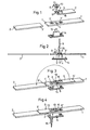
- FIG. 1 Two faceplate 1 and 2 are shown, of which the faceplate 1 has a fixed length dimension, while the faceplate 2 can be cut to length at least at its one end 2 'for the purpose of adaptation to different dimensions of the windows or doors.
- the faceplate 1 is provided near its end 1 'on the one hand with countersunk holes 3' and 3 ", while on the other hand, for example in the middle between these two countersunk holes 3 'and 3", it has, for example, a rectangular polygon opening 4.
- the joint overlap device between the two faceplates 1 and 2 is essentially formed by a tab 5 and a fitting 6.
- the tab 5 has an essentially T-shaped end notch 7 which, with its narrow end region, delimits two cams 8 directed towards one another.
- the shaped piece 6 has a stepped foot part 9, the outline of which corresponds to the polygonal recess 4 in the faceplate 1. Furthermore, it has a head part 10 which is widened relative to the foot part 9 and which is provided in two mutually parallel and facing away from each other with laterally and downwardly open grooves 11.
- the tab 5 with its two cams 8 is first inserted into the grooves 11 of the fitting 6. Then the piece 6, which is connected in this way to the tab 5, is inserted with its foot part 9 into the polygon opening 4 of the face plate 1, so that its head part 10 comes to rest on the top of the face plate 1. If the fitting 6 is now firmly connected to the faceplate 1, for example by riveting, then the grooves 11 are shut off relative to the top of the faceplate 1, so that they form bearing shells for the hinged bracket of the tab 5 in a simple manner.
- the fitting 6 on the faceplate 1 can either be fixed by riveting its base part 9 directly into the polygon opening 4.
- the shaped piece 6 with a through hole 12, into which the rivet bolt 13 of a further shaped piece supported there, preferably serving as a guide for a drive rod and for the fastening screws of the faceplate, is inserted from the underside of the faceplate 1 can.
- the closing head on the rivet bolt 13 of the shaped piece 14 on the upper side of the shaped piece 6 these two shaped pieces 6 and 14 are then simultaneously firmly connected to the faceplate 1, as can be seen particularly clearly in FIG. 2.
- the tab 5 is provided with an embossed countersunk hole 15 which, in the operative position of the hinged tab 5, engages from above into the countersunk hole 3 'of the faceplate 1 such that through both countersunk holes 3' and 15
- a countersunk screw 16 can be screwed into the window or door profile carrying the faceplate 1 and 2.
- the tab 5 lies over its entire length on the upper side of the faceplate 1. If, on the other hand, it is appt in the position according to FIGS. 4 and 6, then it stands with its free position End 5 'by a considerable amount over the free end of the faceplate 1 and thus overlaps the free end 2' of the adjacent faceplate 2 by a corresponding amount.
- the tab 5 is essentially designed as a flat stamped part, so that in its operative position (FIG. 4) it only comes to rest on the outer broad side of the adjacent faceplate 2 and this under the action of the countersunk screw 16 only holds down non-positively.
- the tab 5 must have a U-shaped cross-section, at least in its length range protruding beyond the cuff rail 1 that supports it, and at least one of its U-flanges on the inside 17 are provided with fine toothing 18 which is directed essentially transversely to the main plane of the tab 5.
- a complementary fine toothing 20 is provided on the narrow sides 19 of the faceplate 2 over its length that can be cut to length, which is offset from the normal longitudinal edges 21 of the faceplate 2 by the material thickness of the U-flanges 17 formed on the tab 5.
- the tab 5 is folded out of its disengagement position shown in FIG. 5 into the active position according to FIG. 6, then the fine toothing 18 of its U-flanges 17 come from above the fine teeth 20 on the narrow sides 19 of the faceplate 2 in operative connection and thereby establish a positive interlinking between the two faceplates 1 and 2.
- This positive connection is then securely locked by screwing the screw 16 into the countersunk holes 3 'of the faceplate 1 and 15 of the tab 5.
- the tab 5 on the faceplate 1 does not necessarily have to be arranged such that it can be folded over an angle bend of 180 °. Rather, it is sufficient if the flap 5 can only be folded through an elbow of 90 °. It is therefore easily possible to provide the tab 5 even when a functional member of the connecting rod fitting protrudes from the faceplate 1 near its free end 1 '.
- the devices described above for joint overlap on faceplate rails can be used in particular in connection with connecting rod fittings for windows, doors or the like, for which difficult installation conditions result on the sash or frame profiles. They can be used both as purely frictional hold-downs and for the production of form-fitting cuff rail linkages.
Landscapes
- Engineering & Computer Science (AREA)
- Mechanical Engineering (AREA)
- Civil Engineering (AREA)
- Structural Engineering (AREA)
- Joining Of Corner Units Of Frames Or Wings (AREA)
Description
Die Erfindung betrifft eine Vorrichtung zur Stoßstellenüberlappung an Stulpschienen von Treibstangenbeschlägen für Fenster, Türen od. dgl. mit einer am Ende der einen Stulpschiene mittels eines Gelenks beweglich befestigten Lasche, die im Einbauzustand über das Ende einer benachbarten Stulpschiene stellbar ist, wobei die Lasche und die sie tragende Stulpschiene außerdem Löcher aufweisen, die bei Wirkstellung der Lasche in Decklage zueinander stehen und zur Lagenfixierung der Lasche zusätzlich von einer im Fenster oder in der Tür verankerbaren Schraube durchgriffen sind.The invention relates to a device for joint overlap on face plates of espagnolette fittings for windows, doors or the like. With a movably attached at the end of a face plate by means of a hinge, which can be adjusted in the installed state over the end of an adjacent face plate, the tab and the they also have cuff rails that have holes that are in the top position when the tab is in the active position and that are additionally penetrated by a screw that can be anchored in the window or door to fix the tab in position.
Derartige Vorrichtungen zur Stoßstellenüberlappung werden insbesondere dann benutzt, wenn eine der beiden stumpf gegeneinanderstoßenden Stulpschienen zum Zwecke der Anpassung an unterschiedliche Einbaumaße ablängbar ausgebildet ist und über den vorbestimmten Ablängbereich hinweg keine Senklöcher zur Aufnahme von Befestigungsschrauben aufweisen kann. Die Stoßstellenüberlappung stellt dabei sicher, daß auch das nicht durch eine Schraube festlegbare Ende einer Stulpschiene in seiner funktionsbedingten Einbaulage gehalten wird.Such devices for overlapping joints are used in particular when one of the two butt-jointed faceplates is cut to length for the purpose of adaptation to different installation dimensions and cannot have countersunk holes for receiving fastening screws over the predetermined cutting area. The joint overlap ensures that the end of a faceplate, which cannot be fixed by a screw, is held in its function-related installation position.
Bei marktgängigen Treibstangenbeschlägen ist die die Stoßstellenüberlappung zwischen den einander benachbarten Enden zweier Stulpschienen bildende Lasche in der durch DE-U 72 09 926 offenbarten Art und Weise an der einen Stulpschiene um ein Gelenk beweglich gelagert, das von einem mit seiner Achse normal zur Breitseite dieser Stulpschiene gerichteten Nietbolzen gebildet wird. Dadurch kann die Lasche parallel zur Stulpschienenebene über das Ende der benachbarten Stulpschiene geschwenkt werden und läßt sich sodann in dieser Lage durch Eindrehen einer Schraube arretieren.In commercially available espagnolette fittings, the tab forming the joint overlap between the adjacent ends of two faceplate rails is movably mounted on a faceplate around a joint in the manner disclosed by DE-U 72 09 926, which is normal with one axis with its axis to the broad side of this faceplate directed rivet bolt is formed. As a result, the tab can be pivoted parallel to the faceplate level over the end of the adjacent faceplate and can then be locked in this position by screwing in a screw.
Derartige Vorrichtungen für Stoßstellenüberlappung von Stulpschienen sind jedoch nur dort einsatzfähig, wo die Stulpschienen so eingebaut werden, daß ihre äußere Breitseite bündig mit der Falzumfangsfläche der Fenster- oder Türprofile liegt bzw. geringfügig über diese Falzumfangsfläche vorsteht. Springt hingegen die Falzumfansfläche der Fenster-oder Türprofile gegenüber der äußeren Breitseite der Stulpschienen mehr oder weniger vor, dann lassen sich Vorrichtungen zur Stoßstellenüberlappung nach DE-U 72 09 926 nicht mehr benutzen, weil die Schwenkbewegung ihrer Laschen dann behindert wird.Such devices for joint overlap of faceplates are only usable where the faceplates are installed so that their outer broad side is flush with the rebate peripheral surface of the window or door profiles or protrudes slightly beyond this rebate peripheral surface. If, on the other hand, the fold circumferential surface of the window or door profiles protrudes more or less in relation to the outer broad side of the face plates, then devices for overlapping joints according to DE-U 72 09 926 can no longer be used because the pivoting movement of their tabs is then impeded.
Die Vorrichtung zur Stoßstellenüberlappung nach DE-U 72 09 926 ist im übrigen nur dann einsatzfähig, wenn eine rein kraftschlüssige Halteverbindung zwischen den einander benachbarten Stulpenden für den betreffenden Gebrauchszweck ausreicht.The device for joint overlap according to DE-U 72 09 926 is otherwise only usable if a purely non-positive holding connection between the adjacent cuff ends is sufficient for the purpose in question.
Wird hingegen eine formschlüssige Verkettung zwischen den einander benachbarten Stulpschienenenden benötigt, dann ist diese bekannte Vorrichtung zur Stoßstellenüberlappung nicht einsatzfähig. In diesem Falle müssen vielmehr Vorrichtungen zur Stoßstellenüberlappung an Stuipschienen in Gebrauch genommen werden, wie sie entweder durch.die Literaturstelle aus « Baubeschlag-Magazin •, Heft 6/78, Seite 84, oder aber durch die DE-A-24 49 352 zum Stand der Technik gehören.If, on the other hand, a positive interlinking between the adjacent cuff rail ends is required, then this known device for overlapping joints cannot be used. In this case, devices for overlapping joints on the support rails rather have to be used, as described either by the literature reference from «Baubeschlag-Magazin •,
Bei der Vorrichtung zur Stoßstellenüberlappung nach « Baubeschlag-Magazin ist die die einander benachbarten Enden beider Stulpschienen übergreifende Lasche als im Querschnitt U-förmige Stulpzahnplatte ausgebildet, die in ihrem Steg ein Senkloch aufweist und an der Innenseite ihrer Flansche mit einer Feinverzahnung versehen ist. Der das Senkloch enthaltende Längenbereich der Stulpzahnplatte umgreift das einerseits mit Randausklinkungen versehene und andererseits ein Schraubendurchgangsloch aufweisende Ende der nicht ablängbaren Stulpschiene, während deren anschließender Längenbereich mit der ablängbaren Stulpschiene zusammenwirkt, die an ihren Längskanten über den vorgesehenen Ablängbereich mit Feinverzahnungen versehen ist.In the device for joint overlap according to the «Baubeschlag-Magazin», the tab that overlaps the adjacent ends of both faceplate rails is designed as a faceplate plate with a U-shaped cross-section, which has a countersunk hole in its web and has fine teeth on the inside of its flanges. The length area of the faceplate plate containing the countersunk hole encompasses the end of the non-cut-to-length faceplate, which is provided with edge notches on the one hand and a screw through hole on the other, while its subsequent length area interacts with the cut-to-length faceplate, which is provided with fine toothing on its longitudinal edges over the intended lengthening area.
Die Stulpzahnplatte ist als loses Teil vorhanden und wird zur Herstellung der formschlüssigen Stoßstellenüberlappung auf die einander benachbarten Stulpenden aufgestülpt, so daß die Feinverzahnungen an der Innenseite ihrer Flansche mit den komplementären Feinverzahnungen an den Längskanten der ablängbaren Stulpschiene in Formschlußeingriff gelangen. Durch Eindrehen einer das Senkloch der Stulpzahnplatte und das Durchgangsloch der nicht ablängbaren Stulpschiene durchgreifenden Schraube in das Fenster oder die Tür wird dann der Formschlußeingriff der Stoßstellenüberlappung gesichert.The faceplate is available as a loose part and is put on the adjacent faceplate ends to produce the positive joint overlap, so that the fine teeth on the inside of their flanges with the complementary fine teeth on the longitudinal edges of the cut-to-length faceplate come into positive engagement. The form-locking engagement of the joint overlap is then secured by screwing a screw which penetrates the countersunk hole of the faceplate plate and the through hole of the faceplate which cannot be cut to length into the window or the door.
Es liegt ohne weiteres auf der Hand, daß die Handhabung dieser bekannten Vorrichtung zur Stoßstellenüberlappung an Stulpschienen verhältnismäßig umständlich und zeitraubend ist und daß die als loses Teil vorhandene Stulpzahnplatte auch leicht vorloren gehen kann.It is obvious that the handling of this known device for joint overlap on faceplate rails is relatively cumbersome and time-consuming and that the faceplate plate as a loose part can also be easily preloaded.
Die ebenfalls zur Bildung einer formschlüssigen Verkettung zwischen den einander benachbarten Stulpschienenenden geeignete Vorrichtung zur Stoßstellenüberlappung nach DE-A-2449352 verwendet eine Lasche, die mittels einer lösbar in ein am Ende der einen Stulpschiene vorgesehenes Gewindeloch eindrehbaren Schraube gehalten wird, in dem deren Schaft ein Langloch in der Lasche durchsetzt. Zur Herstellung der formschlüssigen Verkettung muß in das Ende der benachbarten Stulpschiene gleichzeitig mit oder nach dem Ablängvorgang ein glattwandiges Loch eingearbeitet werden, in das ein an die Unterseite der Lasche angeformter Hals formschlüssig zum Eingriff gebracht werden kann. Zur Sicherung der Halteverbindung muß anschließend die Schraube gänzlich in die Gewindebohrung der einen Stulpschiene eingedreht werden, wobei ihr Kopf mit einer eingeformten Verzahnung an die Laschen-Oberseite drückt. Solange die Schraube nicht in das Gewindeloch am Ende der einen Stulpschiene eingesetzt worden ist, bilden diese und die zur Herstellung der formschlüssigen Verkettung dienende Lasche lose Teile, die leicht verloren gehen können, so daß hierfür Ersatz beschafft werden muß, wenn die ordnungsgemäße Beschlagfunktion nicht gefährdet werden soll.The device for joint overlap according to DE-A-2449352, which is also suitable for forming a form-fitting interlinking between the adjacent cuff rail ends, uses a tab which is held by means of a screw which can be removably screwed into a threaded hole provided at the end of the one cuff rail, in the shaft of which an elongated hole is provided interspersed in the tab. To produce the interlocking interlinking, a smooth-walled hole must be worked into the end of the adjacent faceplate simultaneously with or after the cutting process, into which a hole is formed which is formed on the underside of the tab Neck can be positively engaged. To secure the retaining connection, the screw must then be completely screwed into the threaded bore of one faceplate, with its head pressing against the top of the bracket with a molded-in toothing. As long as the screw has not been inserted into the threaded hole at the end of a faceplate, this and the flap used to produce the form-fitting interlinking form loose parts that can easily be lost, so that a replacement must be obtained if the proper fitting function is not jeopardized shall be.
Es wäre zwar denkbar, die die Lasche mit dem einen Ende der Stulpschiene verbindende Spannschraube so zu bemessen, daß sie nur um ein bestimmtes Maß gelockert und nicht gänzlich aus dem Gewindeloch herausgedreht werden muß, um ein begrenztes Abheben der Lasche von den benachbarten Enden der beiden Stulpschienen zu ermöglichen. Dabei könnte die Lasche entweder in Normalrichtung zu ihrer Ebene von den Enden beider Stulpschienen abgehoben werden. Es wäre aber auch denkbar, sie unter Durchführung einer geringen Winkelbewegung von den Enden der beiden Stulpschienen abzuheben, wobei die Winkelbewegung um dasjenige Ende der Lasche stattfindet, welches sich au der das Gewindeloch aufweisenden und die Spannschraube enthaltenden Stulpschiene abstützt.It would be conceivable to dimension the clamping screw connecting the tab to one end of the faceplate so that it only has to be loosened to a certain extent and does not have to be completely unscrewed from the threaded hole in order to limit the lifting of the tab from the adjacent ends of the two Allow faceplates. The tab could either be lifted in the normal direction to its level from the ends of both faceplate rails. However, it would also be conceivable to lift them off the ends of the two faceplate rails by performing a slight angular movement, the angular movement taking place around the end of the tab which is supported on the faceplate which has the threaded hole and contains the tensioning screw.
Damit der unmittelbar an das Ende der die Lasche tragenden Stulpschiene anschließende, zur Aufnahme des Endes der anderen Stulpschiene dienende Bereich von der Lasche völlig freigemacht werden kann, ist es jedoch in beiden Fällen notwendig, die Lasche in ihrer angehobenen Lage noch relativ zu der einen Stulpschiene, und zwar um die Achse der Spannschraube seitwärts zu verschwenken. Diese Handhabungsart der zur Stoßstellenüberlappung dienenden Lasche ist jedoch relativ umständlich und damit montagetechnisch aufwendig.However, in order for the area directly adjoining the end of the faceplate supporting the tab, which serves to receive the end of the other faceplate, to be completely cleared from the tab, it is necessary in both cases to keep the tab in its raised position relative to the one faceplate , namely to pivot sideways about the axis of the clamping screw. However, this type of handling of the tab serving to overlap the joints is relatively cumbersome and therefore complex in terms of assembly technology.
Mit der Erfindung wird bezweckt, die Einsatzmöglichkeiten für eine Vorrichtung zur Stoßstellenüberlappung an Stulpschienen zu verbessern. Daher ist es Ziel der Erfindung, eine gattungsgemäße Vorrichtung zur Stoßstellenüberlappung an Stulpschienen von Treibstangenbeschlägen so zu gestalten, daß sie nicht nur bei allen vorkommenden Einbauarten für die Treibstangenbeschläge mit kraftschlüssiger Wirkung zwischen den benachbarten Stulpschienen einsatzfähig ist, sondern auch dann benutzt werden kann, wenn es darauf ankommt, eine formschlüssige Verkettung zwischen den einander benachbarten Stulpschienenenden zu bewirken, wobei in jeden Falle eine einzige Bewegungsart für die Lasche ausreicht, um diese insgesamt in den oder aus dem Bereich der Stoßstellenüberlappung zu bringen.The purpose of the invention is to improve the possible uses for a device for overlapping joints on faceplate rails. It is therefore the object of the invention to design a generic device for overlapping joints on faceplate rails of espagnolette fittings so that it can be used not only in all types of installation for the espagnolette fittings with a non-positive effect between the adjacent faceplate rails, but can also be used when it is it is important to bring about a form-fitting interlinking between the adjacent cuff rail ends, in each case a single type of movement for the tab being sufficient to bring it overall into or out of the area of the joint overlap.
Die Lösung dieser Aufgabe wird nach der Erfindung im wesentlichen durch die Kennzeichnungsmerkmale des Anspruchs 1 erreicht.This object is achieved according to the invention essentially by the characterizing features of
Unter Einsatz dieser Mittel läßt sich allein durch Eindrehen der die Löcher in der Lasche und in der diese lagernden Stulpschiene durchdringenden Schraube in das Fenster- oder Türprofil eine kraftschlüssige Lagensicherung des benachbarten Stulpschienenendes bewirken.Using these agents, a force-locking securing of the adjacent end of the faceplate can be brought about simply by screwing the screw penetrating the holes in the bracket and in the faceplate bearing it into the window or door profile.
Ist hingegen eine formschlüssig wirkende Vorrichtung zur Stoßstellenüberlappung erwünscht, bei der die Lasche mit im wesentlichen quer zur Stulpebene gerichteten Feinverzahnungen formschlüssig in komplementäre Feinverzahnungen am Ende der benachbarten Stulpschiene in Eingriff gebracht werden kann, dann empfiehlt es sich, zusätzlich die Kennzeichnungsmerkmale des Anspruchs 2 in Benutzung zu nehmen.If, on the other hand, a form-fitting device for overlapping joints is desired, in which the tab can be positively engaged in complementary fine toothing at essentially the end of the adjacent faceplate with fine toothing directed essentially transversely to the faceplate plane, then it is recommended to additionally use the characterizing features of
Vorteilhafte bauliche Ausgestaltungen einer Vorrichtung zur Stoßstellenüberlappung sind durch Benutzung der Merkmale eines oder mehrerer der Ansprüche 3 bis 5 erreichbar.Advantageous structural designs of a device for overlapping joints can be achieved by using the features of one or more of
Durch die im Anspruch 6 aufgezeigte Ausgestaltung wird eine bauliche Weiterbildung für die formschlüssig wirkende Vorrichtung zur Sto- βstellenüberlappung erreicht.As a result of the embodiment shown in
- Figur 1 zeigt etwa in natürlicher Größe und räumlicher Sprengdarstellung die Einzelteile einer Vorrichtung zur Stoßstellenüberlappung an Stulpschienen ;Figure 1 shows approximately in natural size and spatial exploded view, the individual parts of a device for joint overlap on face plates;
- Figur 2 gibt einen Längsschnitt durch eine gebrauchsfertig montierte Vorrichtung zur Sto- βstellenüberlappung an Stulpschienen wieder ;FIG. 2 shows a longitudinal section through a ready-to-use device for overlapping joints on face plates;
- Figur 3 zeigt in räumlicher Draufsichsdarstellung eine kraftschlüssig wirkende Vorrichtung zur Stoßstellenüberlappung vor Herstellung der Überlappungsverbindung ;FIG. 3 shows a three-dimensional top view of a non-positive device for overlapping joints before the overlap connection is established;
- Figur 4 gibt die Vorrichtung zur kraftschlüssigen Stoßstellenüberlappung nach Fig. 3 in ihrer Wirkstellung wieder ;FIG. 4 shows the device for the frictional joint overlap according to FIG. 3 in its operative position;
- Figur 5 stellt in räumlicher Ansicht eine formschlüssig wirkende Vorrichtung zur Stoßstellenüberlappung an Stulpschienen in ihrer unwirksamen Lage dar, währendFigure 5 shows a three-dimensional view of a form-fitting device for butt joint overlap on faceplate in its inactive position, while
- Figur 6 die Vorrichtung nach Fig. 5 im Formschlußeingriff zeigt.Figure 6 shows the device of Fig. 5 in positive engagement.
In Fig. sind zwei Stulpschienen 1 und 2 gezeigt, von denen die Stulpschiene 1 eine fixe Längenabmessung hat, während die Stulpschiene 2 zum Zwecke der Anpassung an unterschiedliche Abmessungen der Fenster oder Türen zumindest an ihrem einen Ende 2' beliebig abgelängt werden kann.In Fig. Two
Die Stulpschiene 1 ist in der Nähe ihres Endes 1' einerseits mit Senklöchern 3' und 3" ausgestattet, während sie andererseits, etwa in der Mitte zwischen diesen beiden Senklöchern 3' und 3", einen beispielsweise rechteckförmigen Mehrkantdurchbruch 4 aufweist.The
Die Vorrichtung zur Stoßstellenüberlappung zwischen den beiden Stulpschienen 1 und 2 wird im wesentlichen von einer Lasche 5 und einem Formstück 6 gebildet. Die Lasche 5 weist dabei eine im wesentlichen T-förmige Endausklinkung 7 auf, die mit ihrem schmalen Endbereich zwei gegeneinander gerichtete Nocken 8 begrenzt.The joint overlap device between the two
Das Formstück 6 hat ein abgesetztes Fußteil 9, dessen Umrißform der Mehrkantausnehmung 4 in der Stulpschiene 1 entspricht. Ferner weist es ein relativ zum Fußteil 9 verbreitertes Kopfteil 10 auf, das in zwei zueinander parallelen und voneinander abgewendeten Stirnflächen jeweils mit seitlich und nach unten offenen Nuten 11 versehen ist.The
In die Nuten 11 des Formstücks 6 wird die Lasche 5 mit ihren beiden Nocken 8 zunächst eingeschoben. Sodann wird das auf diese Weise mit der Lasche 5 in Verbindung gebrachte Formstück 6 mit seinem Fußteil 9 in den Mehrkantdurchbruch 4 der Stulpschiene 1 eingesetzt, so daß dessen Kopfteil 10 auf der Oberseite der Stulpschiene 1 zu liegen kommt. Wird nun das Formstück 6, beispielsweise durch Vernieten, mit der Stulpschiene 1 fest verbunden, dann tritt eine Absperrung der Nuten 11 relativ zur Oberseite der Stulpschiene 1 ein, so daß diese auf einfache Weise Lagerschalen für die klappbare Halterung der Lasche 5 bilden.The
Die Festlegung des Formstückes 6 an der Stulpschiene 1 kann entweder dadurch erfolgen, daß dessen Fußteil 9 unmittelbar in dem Mehrkantdurchbruch 4 festgenietet wird. Es ist aber auch möglich, das Formstück 6 mit einem Durchgangsloch 12 zu versehen, in das von der Unterseite der Stulpschiene 1 her der Nietbolzen 13 eines dort abgestützten, vorzugsweise als Führung für eine Treibstange und für die Befestigungsschrauben der Stulpschiene dienenden, weiteren Formstückes eingesteckt werden kann. Durch Bildung des Schließkopfes am Nietbolzen 13 des Formstückes 14 auf der Oberseite des Formstückes 6 werden dann diese beiden Formstücke 6 und 14 gleichzeitig fest mit der Stulpschiene 1 verbunden, wie das besonders deutlich der Fig. 2 entnommen werden kann.The
Erwähnenswert ist noch, daß die Lasche 5 mit einem eingeprägten Senkloch 15 versehen ist, welches in der Wirkstellung der klappbar gelagerten Lasche 5 von oben her in das Senkloch 3' der Stulpschiene 1 zum Eingriff kommt, derart, daß durch beide Senklöcher 3' und 15 zur Lagensicherung der Lasche 5 eine Senkschraube 16 in das die Stulpschienen 1 und 2 tragende Fenster-oder Türprofil eingedreht werden kann.It is also worth mentioning that the
Beim Vergleich der Fig. 3 und 4 einerseits und der Fig.5 und 6 andererseits wird deutlich, daß die Lasche 5 relativ zur Stulpschiene 1 maximal um einen Winkel von 180° klappbar gehalten ist.When comparing FIGS. 3 and 4 on the one hand and FIGS. 5 and 6 on the other hand, it becomes clear that the
In der aus den Fig. und 5 ersichtlichen Klapplage liegt dabei die Lasche 5 auf ihrer ganzen Länge auf der Oberseite der Stulpschiene 1. Wird sie hingegen in die Stellung nach den Fig. 4 bzw. 6 herumgek)appt, dann steht sie mit ihrem freien Ende 5' um ein beträchtliches Maß über das freie Ende der Stulpschiene 1 vor und überlappt damit das freie Ende 2' der benachbarten Stulpschiene 2 um ein entsprechendes Maß.In the foldable position shown in FIGS. 5 and 5, the
Beim Ausführungsbeispiel nach den Fig. 3 und 4 ist die Lasche 5 im wesentlichen als flaches Stanzteil ausgebildet, so daß sie in ihrer Wirkstellung (Fig.4) lediglich auf der äußeren Breitseite der benachbarten Stulpschiene 2 zur Auflage kommt und diese unter der Wirkung der Senkschraube 16 lediglich kraftschlüssig niederhält.In the embodiment according to FIGS. 3 and 4, the
Wird jedoch eine formschlüssige Verkettung zwischen den beiden einander benachbarten Stulpschienen 1 und 2 gewünscht, dann muß die Lasche 5 wenigstens in ihrem bei Wirkstellung über die sie lagernde Stulpschiene 1 hinausragenden Längenbereich einen U-förmigen Querschnitt aufweisen und an der Innenseite wenigstens eines ihrer U-Flansche 17 mit einer Feinverzahnung 18 versehen werden, die im wesentlichen quer zur Hauptebene der Lasche 5 gerichtet ist.However, if a form-fitting interlinking between the two
Andererseits wird an den Schmalseiten 19 der Stulpschiene 2 über deren ablängbaren Längenabschnitt eine komplementäre Feinverzahnung 20 vorgesehen, die gegenüber den normalen Längskanten 21 der Stulpschiene 2 um die Materialdicke der an der Lasche 5 gebildeten U-Flansche 17 abgesetzt angeordnet ist.On the other hand, a complementary
Wird nach dem Einbau der beiden Stulpschienen 1 und 2 in das Fenster- oder Türprofil die Lasche 5 aus ihrer der Fig. 5 entnehmbaren Ausrückstellung in die Wirkstellung nach Fig. 6 geklappt, dann treten die Feinverzahnungen 18 ihrer U-Flansche 17 von oben her mit den Feinverzahnungen 20 an den Schmalseiten 19 der Stulpschiene 2 in Wirkverbindung und stellen dadurch eine formschlüssige Verkettung zwischen den beiden Stulpschienen 1 und 2 her. Diese Formschlußverbindung wird anschließend durch ein Eindrehen der Schraube 16 in die Senklöcher 3' der Stulpschiene 1 sowie 15 der Lasche 5 sicher arretiert.If, after the installation of the two
Erwähnenswert ist noch, daß die Lasche 5 auf der Stulpschiene 1 nicht unbedingt über einen Winkelbogen von 180° klappbar angeordnet sein muß. Vielmehr reicht es ohne weiteres aus, wenn die Lasche 5 nur um einen Winkelbogen von 90° klappbar ist. Es besteht daher ohne weiteres die Möglichkeit, die Lasche 5 auch dann vorzusehen, wenn aus der Stulpschiene 1 in der Nähe ihres freien Endes 1' ein Funktionsglied des Treibstangenbeschlages herausragt.It is also worth mentioning that the
Die vorstehend beschriebenen Vorrichtungen zur Stoßstellenüberlappung an Stulpschienen sind insbesondere in Verbindung mit Treibstangenbeschlägen für Fenster, Türen od. dgl. einsetzbar, für die sich an den Flügel- oder Rahmenprofilen schwierige Einbauverhältnisse ergeben. Sie lassen sich dabei sowohl als rein kraftschlüssige Niederhalter benutzen als auch für die Herstellung formschlüssiger Stulpschienenverkettungen einsetzen.

Claims (6)
Applications Claiming Priority (2)
| Application Number | Priority Date | Filing Date | Title |
|---|---|---|---|
| DE7819165U | 1978-06-26 | ||
| DE19787819165U DE7819165U1 (en) | 1978-06-26 | 1978-06-26 | DEVICE FOR OVERLAPING JOINT SITES ON CUP RAILS |
Publications (3)
| Publication Number | Publication Date |
|---|---|
| EP0006439A1 EP0006439A1 (en) | 1980-01-09 |
| EP0006439B1 EP0006439B1 (en) | 1981-10-14 |
| EP0006439B2 true EP0006439B2 (en) | 1986-07-30 |
Family
ID=6692732
Family Applications (1)
| Application Number | Title | Priority Date | Filing Date |
|---|---|---|---|
| EP79101558A Expired EP0006439B2 (en) | 1978-06-26 | 1979-05-22 | Joint overlapping device for face plates |
Country Status (3)
| Country | Link |
|---|---|
| EP (1) | EP0006439B2 (en) |
| AT (1) | AT370193B (en) |
| DE (2) | DE7819165U1 (en) |
Families Citing this family (3)
| Publication number | Priority date | Publication date | Assignee | Title |
|---|---|---|---|---|
| DE2925671C2 (en) * | 1979-06-26 | 1990-04-19 | August Bilstein GmbH & Co KG, 5828 Ennepetal | Corner connection in a window, door frame or the like. arranged espagnolette |
| DE9212950U1 (en) * | 1992-09-25 | 1992-12-03 | Siegenia-Frank Kg, 5900 Siegen | Espagnolette fittings for windows, doors, etc. |
| EP1245768A3 (en) * | 2001-03-26 | 2004-01-02 | Gretsch-Unitas GmbH Baubeschläge | Face-plate for an espagnolette for windows, doors or similar, and an espagnoette with such a face-plate |
Family Cites Families (4)
| Publication number | Priority date | Publication date | Assignee | Title |
|---|---|---|---|---|
| DE2449352C2 (en) * | 1974-10-17 | 1983-09-29 | Carl Fuhr Gmbh & Co, 5628 Heiligenhaus | Face plate cover rail for a connecting rod fitting, in particular tilt and turn fitting for windows, doors or the like |
| DE2520668A1 (en) * | 1975-05-09 | 1976-11-18 | Fuhr C Fa | Actuated rod system for windows and doors - has top hat cross section covering profile for actuating rods |
| FR2335680A1 (en) * | 1975-12-15 | 1977-07-15 | Ferco Int Usine Ferrures | Window pushrod connecting assembly - uses two engaging toothed racks with plain recesses to fit cover strip screw |
| DE2635446C2 (en) * | 1976-08-06 | 1982-12-30 | Siegenia-Frank Kg, 5900 Siegen | Length-adjustable rod coupling on connecting rod fittings for windows, doors or the like. |
-
1978
- 1978-06-26 DE DE19787819165U patent/DE7819165U1/en not_active Expired
-
1979
- 1979-05-14 AT AT0356479A patent/AT370193B/en not_active IP Right Cessation
- 1979-05-22 DE DE7979101558T patent/DE2960980D1/en not_active Expired
- 1979-05-22 EP EP79101558A patent/EP0006439B2/en not_active Expired
Also Published As
| Publication number | Publication date |
|---|---|
| EP0006439A1 (en) | 1980-01-09 |
| DE2960980D1 (en) | 1981-12-24 |
| AT370193B (en) | 1983-03-10 |
| EP0006439B1 (en) | 1981-10-14 |
| ATA356479A (en) | 1982-07-15 |
| DE7819165U1 (en) | 1978-10-05 |
Similar Documents
| Publication | Publication Date | Title |
|---|---|---|
| DE102009012438B4 (en) | pinheader | |
| DE102006016045B4 (en) | Device for releasably holding a surface element and its use | |
| DE3639276A1 (en) | FURNITURE HINGE WITH QUICK RELEASE | |
| EP3425155B1 (en) | Finger guard for a door | |
| DE2750307C2 (en) | Corner or T connection of two profiles | |
| WO2014095389A1 (en) | Door system | |
| DE102010049782A1 (en) | Hollow profile strip for installing profile frame for protective grid, has multiple functional compartments formed between profile cover surface and profile base for receiving multiple functional elements | |
| CH645155A5 (en) | DOOR BAND. | |
| DE3412953C2 (en) | ||
| EP0006439B2 (en) | Joint overlapping device for face plates | |
| DE202009003438U1 (en) | pinheader | |
| DE20019594U1 (en) | Adjustment device of a frame | |
| DE102014119021B4 (en) | Arrangement for attaching a post made of plastic to a frame strip of a window or a door by means of a post connector | |
| DE19808847C2 (en) | Door or window fittings | |
| DE19719113A1 (en) | Door system with door frame and lining | |
| EP3168394B1 (en) | Block for a door opener or a strike plate | |
| DE2736333A1 (en) | Furniture hinge assembly system - achieves locking together of assembly parts by tongue-carrying rotatable locking element | |
| DE9114374U1 (en) | Espagnolette fittings for windows, doors, etc. | |
| DE202005001072U1 (en) | Lock strip for mounting on a door/window frame comprises a lock strip profile provided with a pocket for receiving a locking bolt or a catch bolt and arranged off-center from the longitudinal central line of a fixing flange | |
| DE3500423A1 (en) | Hinge, especially for furniture | |
| DE19502362C2 (en) | Positioning device for fittings | |
| DE19734647B4 (en) | Fitting part on a wing or a fixed frame of a window, a door od. Like. | |
| DE29600891U1 (en) | Security device | |
| DE2445149A1 (en) | Door hinge mounting for steel surrounds - frame surround recessed for slide acting as hinge adjuster | |
| EP2947247A1 (en) | Residential skylight with an adjustable hinge |
Legal Events
| Date | Code | Title | Description |
|---|---|---|---|
| PUAI | Public reference made under article 153(3) epc to a published international application that has entered the european phase |
Free format text: ORIGINAL CODE: 0009012 |
|
| AK | Designated contracting states |
Designated state(s): CH DE FR |
|
| 17P | Request for examination filed | ||
| GRAA | (expected) grant |
Free format text: ORIGINAL CODE: 0009210 |
|
| AK | Designated contracting states |
Designated state(s): CH DE FR |
|
| REF | Corresponds to: |
Ref document number: 2960980 Country of ref document: DE Date of ref document: 19811224 |
|
| PLBI | Opposition filed |
Free format text: ORIGINAL CODE: 0009260 |
|
| PLBI | Opposition filed |
Free format text: ORIGINAL CODE: 0009260 |
|
| 26 | Opposition filed |
Opponent name: WINKHAUS TECHNIK GMBH & CO. KG Effective date: 19820713 |
|
| 26 | Opposition filed |
Opponent name: WILH. FRANK GMBH Effective date: 19820710 |
|
| PUAH | Patent maintained in amended form |
Free format text: ORIGINAL CODE: 0009272 |
|
| STAA | Information on the status of an ep patent application or granted ep patent |
Free format text: STATUS: PATENT MAINTAINED AS AMENDED |
|
| 27A | Patent maintained in amended form |
Effective date: 19860730 |
|
| AK | Designated contracting states |
Kind code of ref document: B2 Designated state(s): CH DE FR |
|
| EN3 | Fr: translation not filed ** decision concerning opposition | ||
| PGFP | Annual fee paid to national office [announced via postgrant information from national office to epo] |
Ref country code: DE Payment date: 19890325 Year of fee payment: 11 |
|
| PGFP | Annual fee paid to national office [announced via postgrant information from national office to epo] |
Ref country code: FR Payment date: 19890519 Year of fee payment: 11 |
|
| PG25 | Lapsed in a contracting state [announced via postgrant information from national office to epo] |
Ref country code: DE Effective date: 19910201 |
|
| PGFP | Annual fee paid to national office [announced via postgrant information from national office to epo] |
Ref country code: CH Payment date: 19910328 Year of fee payment: 13 |
|
| PG25 | Lapsed in a contracting state [announced via postgrant information from national office to epo] |
Ref country code: CH Effective date: 19920531 |
|
| REG | Reference to a national code |
Ref country code: CH Ref legal event code: PL |
|
| PG25 | Lapsed in a contracting state [announced via postgrant information from national office to epo] |
Ref country code: FR Effective date: 19950131 |
|
| REG | Reference to a national code |
Ref country code: FR Ref legal event code: ST |
|
| PG25 | Lapsed in a contracting state [announced via postgrant information from national office to epo] |
Ref country code: FR Effective date: 19900531 |