EP0620528A1 - Method for storing parcels and apparatus for carrying out this method - Google Patents
Method for storing parcels and apparatus for carrying out this method Download PDFInfo
- Publication number
- EP0620528A1 EP0620528A1 EP94105359A EP94105359A EP0620528A1 EP 0620528 A1 EP0620528 A1 EP 0620528A1 EP 94105359 A EP94105359 A EP 94105359A EP 94105359 A EP94105359 A EP 94105359A EP 0620528 A1 EP0620528 A1 EP 0620528A1
- Authority
- EP
- European Patent Office
- Prior art keywords
- piece goods
- computer
- drawer
- storage
- general cargo
- Prior art date
- Legal status (The legal status is an assumption and is not a legal conclusion. Google has not performed a legal analysis and makes no representation as to the accuracy of the status listed.)
- Granted
Links
Images

Classifications
-
- G—PHYSICS
- G01—MEASURING; TESTING
- G01B—MEASURING LENGTH, THICKNESS OR SIMILAR LINEAR DIMENSIONS; MEASURING ANGLES; MEASURING AREAS; MEASURING IRREGULARITIES OF SURFACES OR CONTOURS
- G01B21/00—Measuring arrangements or details thereof, where the measuring technique is not covered by the other groups of this subclass, unspecified or not relevant
- G01B21/02—Measuring arrangements or details thereof, where the measuring technique is not covered by the other groups of this subclass, unspecified or not relevant for measuring length, width, or thickness
-
- B—PERFORMING OPERATIONS; TRANSPORTING
- B65—CONVEYING; PACKING; STORING; HANDLING THIN OR FILAMENTARY MATERIAL
- B65G—TRANSPORT OR STORAGE DEVICES, e.g. CONVEYORS FOR LOADING OR TIPPING, SHOP CONVEYOR SYSTEMS OR PNEUMATIC TUBE CONVEYORS
- B65G1/00—Storing articles, individually or in orderly arrangement, in warehouses or magazines
- B65G1/02—Storage devices
- B65G1/04—Storage devices mechanical
- B65G1/137—Storage devices mechanical with arrangements or automatic control means for selecting which articles are to be removed
- B65G1/1371—Storage devices mechanical with arrangements or automatic control means for selecting which articles are to be removed with data records
-
- G—PHYSICS
- G06—COMPUTING; CALCULATING OR COUNTING
- G06Q—INFORMATION AND COMMUNICATION TECHNOLOGY [ICT] SPECIALLY ADAPTED FOR ADMINISTRATIVE, COMMERCIAL, FINANCIAL, MANAGERIAL OR SUPERVISORY PURPOSES; SYSTEMS OR METHODS SPECIALLY ADAPTED FOR ADMINISTRATIVE, COMMERCIAL, FINANCIAL, MANAGERIAL OR SUPERVISORY PURPOSES, NOT OTHERWISE PROVIDED FOR
- G06Q10/00—Administration; Management
- G06Q10/08—Logistics, e.g. warehousing, loading or distribution; Inventory or stock management
Abstract
Description
Die Erfindung betrifft ein Verfahren zur Lagerung von Stückgut nach dem Oberbegriff des Anspruches 1 und eine Vorrichtung zur Durchführung eines solchen Verfahrens nach dem Oberbegriff des Anspruches 9.The invention relates to a method for storing piece goods according to the preamble of
Insbesondere im Apothekenbereich ist es üblich, die verschiedenen Packungen in Schubladen abzulegen. Als Ordnungsmerkmal dient hierbei in der Regel der Produktname. Dies hat aber den Nachteil, daß die zur Verfügung stehenden Schubladenflächen nicht optimal zur Lagerung der Arzneiartikel ausgenutzt werden. Dadurch wird in einer Apotheke erheblicher Raum zur Lagerung der Arzneimittel benötigt.In the pharmacy area in particular, it is customary to put the various packs in drawers. The product name is usually used as a classification feature. However, this has the disadvantage that the available drawer surfaces are not optimally used for storing the medicinal products. As a result, considerable space is required in a pharmacy for storing the pharmaceuticals.
Bei dem gattungsgemäßen Verfahren (DE-PS 40 26 449) werden Stückgüter auf einer Palette gelagert, auf der die Stückgüter zum eigentlichen Endlager transportiert werden. Wie die auf der Palette gelagerten Stückgüter in das Endlager eingebracht und aus ihm entnommen werden, ist nicht beschrieben. Wesentlich für dieses bekannte Verfahren ist ein Zwischenspeicher, auf dem die vermessenen und identifizierten Stückgüter in beliebiger Reihenfolge positioniert werden. Damit die Palette optimal beladen werden kann, müssen jedoch die Form und die Abmessung einer größeren Zahl von Stückgütern, etwa 30 %, bekannt sein. Erst aufgrund dieser Vorkenntnis einer bestimmten Zahl von Stückgütern kann die Palette so beladen werden, daß sie optimal befüllt werden kann. Die Zwischenschaltung des Zwischenspeichers verteuert die verwendete Vorrichtung und erhöht die Einlagerungszeiten.In the generic method (DE-PS 40 26 449) piece goods are stored on a pallet on which the piece goods are transported to the actual repository. How the general cargo stored on the pallet is brought into and removed from the repository is not described. What is important for this known method is an intermediate store on which the measured and identified piece goods are positioned in any order. However, in order for the pallet to be loaded optimally, the shape and dimensions of a larger number of piece goods, approximately 30%, must be known. Only on the basis of this prior knowledge of a certain number of piece goods can the pallet be loaded in such a way that it can be optimally filled. The interposition of the buffer makes the device used more expensive and increases the storage times.
Die Stückgüter werden so auf der Palette zusammengestellt, daß das im Zwischenspeicher befindliche Stückgut mit der größten Grundfläche oder die Stückgüter gleicher Höhe, die zusammen die größte Grundfläche einnehmen, in einer Ecke der Palette angeordnet werden. Die Stückgüter abweichender, jedoch gleicher Höhe werden dann in der gegenüberliegenden Ecke der Palette angeordnet. Bei der weiteren Befüllung der Palette wird so vorgegangen, daß die Stückgüter so gestapelt werden, daß sich immer möglichst große, zusammenhängende, ebene, horizontale Flächen ergeben. Bei diesem bekannten Verfahren wird somit davon ausgegangen, möglichst in ihrer Form gleiche oder gleichartige Stückgüter zusammenzusetzen, um die Forderung hinsichtlich der zusammenhängenden, ebenen, horizontalen Flächen zu erreichen.The piece goods are put together on the pallet in such a way that the piece goods with the largest base area or the piece goods of the same height, which together take up the largest base area, are located in a corner of the pallet. The piece goods of different, but the same height are then arranged in the opposite corner of the pallet. When the pallet is filled further, the piece goods are stacked in such a way that the largest possible, coherent, flat, horizontal surfaces result. In this known method it is assumed that the same or similar piece goods are put together as far as possible in order to achieve the requirement with regard to the coherent, flat, horizontal surfaces.
Der Erfindung liegt die Aufgabe zugrunde, das gattungsgemäße Verfahren und die gattungsgemäße Vorrichtung so auszubilden, daß die Stückgüter innerhalb kürzester Zeit so gelagert werden können, daß der vorhandene Lagerraum optimal genutzt wird und dennoch eine einfache Entnahme des Stückgutes aus dem Lager möglich ist.The invention has for its object to design the generic method and the generic device so that the piece goods can be stored within a very short time so that the available storage space is used optimally and yet easy removal of the piece goods from the warehouse is possible.
Diese Aufgabe wird beim gattungsgemäßen Verfahren erfindungsgemäß mit den kennzeichnenden Merkmalen des Anspruches 1 und bei der gattungsgemäßen Vorrichtung erfindungsgemäß mit den kennzeichnenden Merkmalen des Anspruches 9 gelöst.This object is achieved in the generic method according to the invention with the characterizing features of
Beim erfindungsgemäßen Verfahren werden die vermessenen und identifizierten Stückgüter ohne Zwischenlagerung in einem Zwischenspeicher in das Regal- oder Schubladenlager eingelagert. Als Meßgröße zur Auswahl der geeigneten Lagerstelle werden die Kantenlängen des Stückgutes verwendet. Anhand der Vermessung des Stückgutes wird unter Berücksichtigung des freien Lagerplatzes im Lager berechnet, in welcher Lage das Stückgut an der Lagerstelle untergebracht werden kann, um eine optimale Flächenausnutzung zu ermöglichen. Beim erfindungsgemäßen Verfahren ist die Kenntnis einer größeren Zahl von Stückgütern hinsichtlich Form und Abmessungen vor dem Einlagerungsvorgang nicht notwendig. Die Stückgüter werden vielmehr in der Reihenfolge, in der sie anfallen, vermessen, identifiziert und dann zum jeweiligen Lagerplatz gebracht. Bei dieser chaotischen Lagerung werden nicht etwa gleich große Stückgüter möglichst zusammengestellt und abgelegt, sondern es können wahllos unterschiedliche Stückgutgrößen im Regal- oder Schubladenlager nebeneinander angeordnet werden. Es ist dadurch ohne weiteres möglich, daß im Lager neben einem großen Stückgut ein hinsichtlich seiner Abmessungen völlig anders gestaltetes, insbesondere kleineres Stückgut gelagert wird. Die jeweiligen Lagerstellen der Stückgüter werden mit dem Rechner erfaßt, so daß mühelos das gewünschte Stückgut dem Lager entnommen werden kann. Es hat sich gezeigt, daß sich bei Einsatz des erfindungsgemäßen Verfahrens eine Lagerplatzersparnis von wenigstens 50 % ergibt. Beim erfindungsgemäßen Verfahren handelt es sich nicht nur um eine Platzoptimierung, sondern um die komplette Erfüllung der logistischen Aufgabe, angeliefertes Stückgut optimal in dem dafür vorhandenen Lagerraum unterzubringen und auch wieder auszugeben.In the method according to the invention, the measured and identified piece goods are stored in the buffer or drawer storage without intermediate storage in an intermediate store. The edge lengths of the piece goods are used as the measurement variable for the selection of the suitable bearing point. On the basis of the measurement of the piece goods, taking into account the free storage space in the warehouse, the position in which the piece goods can be accommodated at the storage location is calculated in order to enable optimal use of space. In the method according to the invention, knowledge of a larger number of piece goods with regard to shape and dimensions is not necessary before the storage process. Rather, the piece goods are measured, identified and then brought to the respective storage location in the order in which they occur. In this chaotic storage, items of the same size are not put together and stored where possible, but different sizes of items can be arranged side by side in the rack or drawer storage. It is thereby easily possible that in addition to a large piece of goods, a piece of goods which is designed completely differently in terms of its dimensions, in particular smaller piece of goods, is stored in the warehouse. The respective storage locations of the piece goods are recorded with the computer, so that the desired piece goods can be easily removed from the warehouse. It has shown, that a storage space saving of at least 50% results when using the method according to the invention. The method according to the invention is not just a matter of space optimization, but rather of completely fulfilling the logistical task of optimally accommodating the delivered general cargo in the storage space provided for this purpose and also of issuing it again.
Die Abgabe der Stückgüter kann manuell oder vorteilhaft durch ein Handhabungsgerät erfolgen. Bei der manuellen Ablage kann ein Rechner beispielsweise über einen an eine Schnittstelle angeschlossenen Drucker eine Ablageliste ausdrucken, anhand der das Personal die Stückgüter zum Beispiel in Verbindung mit einem optischen Koordinatensystem an den Lagerstellen einräumen kann. Die jeweils zu verwendende Lagerstelle wird dabei vorteilhaft von außen gekennzeichnet, beispielsweise mittels eines rechnergesteuerten optischen Zeigers. Bei Verwendung eines Handhabungsgerätes erhält dieses vorteilhaft ein entsprechendes Signal vom Rechner, nimmt das vermessene Stückgut auf und legt es in der richtigen Lage an der richtigen Lagerstelle ab.The piece goods can be released manually or advantageously by a handling device. With manual storage, a computer can, for example, print out a storage list via a printer connected to an interface, on the basis of which the staff can arrange the piece goods at the storage locations, for example in connection with an optical coordinate system. The bearing point to be used in each case is advantageously marked from the outside, for example by means of a computer-controlled optical pointer. When using a handling device, this advantageously receives a corresponding signal from the computer, picks up the measured piece goods and places it in the correct position at the correct storage location.
Das Stückgut wird beim erfindungsgemäßen Verfahren nicht mehr alphabetisch nach dem Produktnamen im Lager abgelegt, sondern ausschließlich im Hinblick auf seine Stückgutgröße, so daß der zur Verfügung stehende Lagerraum optimal ausgenutzt werden kann.In the method according to the invention, the piece goods are no longer stored alphabetically according to the product name in the warehouse, but only with regard to their piece goods size, so that the available storage space can be optimally used.
Mit der erfindungsgemäßen Vorrichtung wird das Stückgut mittels des Handhabungsgerätes in das Regal- oder Schubladenlager gebracht und dort abgelegt. Soll das Stückgut diesem Endlager entnommen werden, wird es mit dem Handhabungsgerät erfaßt und der Abgabeeinheit übergeben. Sie kann eine Transportvorrichtung für das Stückgut sein, aber auch ein Ablagetisch und dergleichen.With the device according to the invention, the piece goods are brought into the rack or drawer storage by means of the handling device and stored there. If the general cargo is to be removed from this repository, it is recorded with the handling device and transferred to the delivery unit. they can be a transport device for the piece goods, but also a storage table and the like.
Weitere Merkmale der Erfindung ergeben sich aus den weiteren Ansprüchen, der Beschreibung und den Zeichnungen.Further features of the invention result from the further claims, the description and the drawings.
Die Erfindung wird anhand eines in den Zeichnungen dargestellten Ausführungsbeispieles näher erläutert. Es zeigen
- Fig. 1A und Fig. 1B
- in schematischer Darstellung den Verfahrensablauf zum Einlagern von Stückgut in ein Lager,
- Fig. 2A bis Fig. 2C
- in schematischer Darstellung das Ordnungsprinzip des Stückgutes im Lager,
- Fig. 3
- im Schnitt und in schematischer Darstellung ein vor einem Lager angeordnetes Handhabungsgerät,
- Fig. 4
- in schematischer Darstellung eine Abgabeeinheit, mit der Stückgut von einer Transporteinheit zu einer Abnahmestelle transportierbar ist.
- Figures 1A and 1B
- a schematic representation of the procedure for storing general cargo in a warehouse,
- 2A to 2C
- a schematic representation of the principle of organization of the general cargo in the warehouse,
- Fig. 3
- in section and in a schematic representation a handling device arranged in front of a bearing,
- Fig. 4
- in a schematic representation, a delivery unit with which piece goods can be transported from a transport unit to a delivery point.
Mit dem im folgenden beschriebenen Verfahren ist es möglich, Stückgut so in einem Lager unterzubringen, daß der zur Verfügung stehende Lagerraum optimal genutzt wird. Im Ausführungsbeispiel wird dieses Verfahren anhand des Stückgutumsatzes in einer Apotheke im einzelnen beschrieben. Dieses Verfahren kann aber selbstverständlich überall dort eingesetzt werden, wo Stückgut gelagert und entnommen wird.With the method described below, it is possible to accommodate general cargo in a warehouse in such a way that the available storage space is optimally used. In the exemplary embodiment, this method is based on the General cargo sales in a pharmacy described in detail. However, this process can of course be used wherever general cargo is stored and removed.
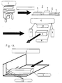
Anhand der Fig. 1A und 1B wird das Verfahren näher erläutert. Wird das Stückgut in Gebinden, wie Kartons und dgl., angeliefert, dann werden die Einzelpackungen diesen Gebinden entnommen und lose auf eine Transporteinrichtung 2 einer Vereinzelungseinheit 3 geschüttet. Eine Vorsortierung der einzelnen Packungen beispielsweise hinsichtlich ihrer Größe ist nicht erforderlich. In der Vereinzelungseinheit 3 wird das einzelne Stückgut, beispielsweise Packungen, in bekannter Weise vereinzelt. Beispielsweise kann diese Vereinzelung durch Vibrationsförderung erfolgen. Das Stückgut 1 wird dann hintereinander einer Erfassungseinrichtung 4 zugeführt, in der Leseeinrichtungen 5 bis 8, beispielsweise Scanner, vorgesehen sind. Mit diesen Leseeinrichtungen 5 bis 8 kann ein am Stückgut 1 vorgesehener Barcode gelesen werden. Bei quaderförmigen Packungen 1 befinden sich diese Barcodes üblicherweise an den Schmalseiten, am Boden oder im Deckel. Darum sind die Leseeinrichtungen 5 bis 8 vorteilhaft so angeordnet, daß sie diese vier Seiten des Stückgutes 1 erfassen können. Die Leseeinrichtungen 5 bis 8 bzw. die Erfassungseinrichtung 4 sind an eine (nicht dargestellte) Rechnereinheit angeschlossen, in der eine Datenbank installiert ist, in welcher sämtliche verfügbaren Präparate mit ihrer zugehörigen Pharmazentralnummer (Barcode) abgelegt sind.The method is explained in more detail with reference to FIGS. 1A and 1B. If the piece goods are delivered in containers such as cardboard boxes and the like, the individual packs are removed from these containers and loosely poured onto a
Die Erfassungseinrichtung 4 ist vorteilhaft nahe dem Ende der Transporteinrichtung 2 der Vereinzelungseinheit 3 angeordnet. Damit die Leseeinrichtungen 5 bis 8 die entsprechenden Seiten der Packung 1 erfassen können, ist die Transporteinrichtung 2 in diesem Bereich nach unten und nach außen durch eine durchsichtige Fläche, beispielsweise eine Glasplatte, unterbrochen. Sobald das Stückgut 1 in diesen durchsichtigen Bereich der Transporteinrichtung 2 gelangt, können die Leseeinrichtungen 5 bis 8 die entsprechenden Seiten des Stückgutes 1 erfassen und einen dort vorhandenen Barcode lesen. Anhand dieses Barcodes oder auch durch OCR-Lesung wird die jeweilige Packung 1 identifiziert. Diese Identifizierung kann während des Transports oder auch am Ende des Transports erfolgen.The
Sollte die Packung 1 eine ungünstige Lage in bezug auf die Leseeinrichtungen 5 bis 8 aufweisen, so daß der Barcode nicht erfaßt wird, dann erhält der Rechner ein entsprechendes Signal. Dadurch schaltet der Rechner seinerseits eine (nicht dargestellte) Aussortiereinrichtung ein, mit der das nicht identifizierbare Stückgut 1 von der Transporteinrichtung 2 zurück zum Beginn der Transporteinrichtung befördert wird. Eine solche Aussortiereinrichtung kann beispielsweise eine mechanisch arbeitende Abweisklappe sein, die sich im Transportweg des Stückgutes befindet und in dessen Transportweg geschaltet wird, durch welche das Stückgut aus der Transportbahn gelenkt wird. Die Klappe kann aber auch im Boden der Transportbahn vorgesehen sein und wegklappen, sobald sich das Stückgut auf ihr oder kurz vor ihr befindet. Es fällt dann beispielsweise auf eine darunter befindliche Rückführeinrichtung, mit der dieses Stückgut zum Anfang der Transporteinrichtung 2 zurückgefordert wird. Von dort gelangt es erneut auf die Transporteinrichtung 2. Es ist dann davon auszugehen, daß das Stückgut 1 nunmehr in eine solche Lage auf der Transporteinrichtung 2 gelangt, daß der Barcode von den Leseeinrichtungen 5 bis 8 erfaßt werden kann. Gegebenenfalls muß dieses Stückgut 1 erneut zum Anfang der Transporteinrichtung 2 zurückgefördert werden.If the
Das nicht lesbare Stückgut 1 kann beispielsweise auch durch Preßluft, die beispielsweise von unten durch die Transporteinrichtung 2 auf das Stückgut 1 wirkt, von der Transportbahn weggeblasen und auf eine Rückführeinrichtung oder dergleichen gefördert werden.The
Nachdem mittels der Leseeinrichtungen 5 bis 8 das Stückgut 1 identifiziert worden ist, gelangt es beim weiteren Transport zu einer Vermessungseinrichtung 9, mit der das jeweilige Stückgut in seinen Außenabmessungen vermessen wird. Die Vermessung kann elektrisch, elektronisch, mechanisch, mit Ultraschall und dgl. erfolgen. Im dargestellten Ausführungsbeispiel hat die Vermessungseinrichtung 9 optische Meßgeräte 10, die Lichtschranken, Sensoren, Kameras, Ultraschall oder dgl. sein oder mechanisch arbeiten können. Im Ausführungsbeispiel ist die Vermessungseinrichtung 9 mit drei CCD-Zeilenkameras ausgestattet, mit denen das Stückgut 1 in seinen drei Koordinaten erfaßt werden kann. Diese drei Kameras 10 sind in Fig. 1A symbolisch durch die drei Raumkoordinaten angedeutet. Die drei Kameras 10 sind an den Rechner angeschlossen und übermitteln die entsprechenden Meßwerte der Packung 1. Anhand der drei Abmessungen des Stückgutes 1 kann der Rechner das Volumen des Stückgutes 1 bzw. die Lagerfläche des Stückgutes berechnen. So läßt sich die geeignetste Fläche im Hinblick auf die Optimierung des Gesamtlagers berechnen, auf die das Stückgut 1 in der Lagerstellung gelegt werden kann.After the
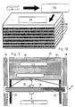
Im Rechner ist der verfügbare Lagerraum (z.B. Schubladenfläche x Nutzhöhe) eines Lagers 11 (Fig. 1B) gespeichert. Dieses Lager 11 ist beispielsweise ein Schubladenlager, wie es in Apotheken häufig eingesetzt wird. In den einzelnen Schubladen 12 wird das jeweilige Stückgut gelagert. Anhand der von der Vermessungseinrichtung 9 an den Rechner gelieferten Maßangaben überprüft der Rechner, an welcher Lagerstelle das gemessene Stückgut unter optimaler Raumausnutzung untergebracht werden kann. Das Stückgut 1 wird dann in noch zu beschreibender Weise an diese Lagerstelle gebracht. Der Rechner erhält dann ein entsprechendes Signal, daß diese Lagerstelle nunmehr besetzt ist. Zudem ist infolge der Erfassungseinrichtung 4 der Rechner auch darüber informiert, welches Produkt sich an dieser Lagerstelle befindet. Wird darum dieses Produkt später vom Apotheker angefordert, kann es von einem entsprechenden Handhabungsgerät dem Lager 11 entnommen werden. Dabei erhält der Rechner wiederum ein Signal, daß diese Lagerstelle wieder frei ist. Außerdem wird der Rechner dann auch darüber informiert, daß ein bestimmtes Präparat entnommen worden ist. Auf diese Weise ist auch jederzeit eine kontinuierliche Bestandsführung der Präparate gewährleistet. Das entsprechende Programm des Rechners ist vorteilhaft so ausgebildet, daß beispielsweise bei einem vorgegebenen Minimalbestand des jeweiligen Präparates automatisch ein Bestellformular ausgedruckt wird, das vom Apotheker nur noch abzuzeichnen ist. Auf diese Weise ist sichergestellt, daß die Präparate stets in der Apotheke vorrätig sind.The available storage space (e.g. drawer area x usable height) of a storage 11 (FIG. 1B) is stored in the computer. This
Das Lager 11 ist vorteilhaft CNC-gesteuert. Hierzu ist das Lager 11 an den Rechner angeschlossen. Mit ihm wird die jeweilige Schublade 12 ausgefahren, in der sich die für das Stückgut 1 vorgesehene freie Lagerstelle befindet.The
Als Lager 11 kann ein überdimensionaler Schubladenschrank verwendet werden, dessen Schubladen 12 beispielsweise mittels Teleskopstangen ein- und ausgefahren werden. Als Antriebe für die Schubladen 12 können Zahnstangentriebe, Pneumatik- oder Hydraulikantriebe und dergleichen eingesetzt werden, die jeweils über den Rechner gesteuert betätigt werden. Dadurch ist ein vollautomatisches Be- und Entladen der Schubladen möglich. Zum Be- und Entladen des Lagers 11 ist ein Handhabungsgerät 13 vorgesehen, das vorzugsweise ein n-achsiger Roboter ist. Ein solcher Roboter kann ein Portalroboter oder ein herkömmlicher Roboter mit mehreren Bewegungsachsen sein. In Fig. 3 ist ein bevorzugtes Ausführungsbeispiel eines Handhabungsgerätes in Form eines Portalroboters dargestellt. Er nimmt nur wenig Platz in Anspruch und hat kurze Zugriffszeiten. Der Portalroboter 13 hat zwei im Bereich neben dem Lager 11 angeordnete Führungsschienen 14 und 15, auf denen ein Querträger 16 verfahrbar ist. Er erstreckt sich zwischen den beiden Führungsschienen 14 und 15 und liegt im Bereich oberhalb des Regals 11. Auf den Führungsschienen 14, 15 kann der Querträger 16 in Verschieberichtung der Schubladen 12 verfahren werden.An oversized drawer cabinet can be used as the
Längs des Querträgers 16 ist ein senkrecht zu ihm sich erstreckender Vertikalträger 17 verfahrbar, längs dem in Höhenrichtung eine (nicht dargestellte) Greifeinrichtung verfahrbar ist. Mit ihr kann das Stückgut der jeweiligen Schublade 12 entnommen bzw. in der Schublade abgelegt werden. Der Portalroboter 13 ist an den Rechner angeschlossen und wird durch ihn so gesteuert, daß die Greifeinrichtung die jeweilige Lagerstelle anfährt.A
Die Schublade 12 des Lagers 11 ist längs Führungsschienen 18 und 19 mit den beschriebenen Antrieben verfahrbar. Über den Rechner wird die jeweils ein- bzw. auszufahrende Schublade 12 angesteuert und bevorzugt nur so weit ausgefahren, bis die jeweilige Lagerstelle im Griffbereich der Greifeinrichtung des Portalroboters 13 liegt. Befindet sich diese Lagerstelle in der Nähe der Blende der Schublade 12, dann muß sie nur wenig aus dem Lager 11 ausgefahren werden, wodurch erheblich Zeit eingespart wird.The
Die Transporteinrichtung 2, auf der die Stückgüter 1 nacheinander durch die Vereinzelungseinheit 3, die Erfassungseinrichtung 4 und die Vermessungseinrichtung 9 transportiert werden, erstreckt sich so weit, daß die Stückgüter von der Greifeinrichtung des Portalroboters 13 ergriffen werden können.The
Anstelle der beschriebenen Schubladen kann das Lager 11 auch jede andere geeignete Ablage aufweisen. Beispielsweise können Ablagen eingesetzt werden, die um eine vertikale Achse dreh- oder schwenkbar sind.Instead of the drawers described, the bearing 11 can also have any other suitable storage. For example, shelves can be used that can be rotated or pivoted about a vertical axis.
Aufgrund der Vermessung des Stückgutes 1 in der Vermessungseinrichtung 9 ist die örtliche Lage und die dreidimensionale Größe des Stückgutes 1 relativ zur Transportrichtung bekannt. Die Datenbank des Rechners stellt nunmehr eine Zuordnung zwischen der Packungsgröße in den ihr eigenen und durch die Vermessung bekannten drei Dimensionen und dem Produkt selbst mit seiner zugehörigen Pharmazentralnummer (Barcode) sowie deren Lage und Position auf der Packung her. Der Rechner erhält entsprechende Signale, aufgrund derer er der Greifeinrichtung des Portalroboters 13 entsprechende Steuersignale übersendet. Die Greifeinrichtung wird dann in bezug auf das zu fassende Stückgut 1 eingestellt. So wird bei einer entsprechend großen Packung die Öffnungsweite der Greiffinger entsprechend groß eingestellt. Auch der Greifdruck kann variiert werden, je nachdem, ob das Stückgut weich oder hart ist. Wenn darum die Greifeinrichtung des Portalroboters 13 an das Stückgut 1 herangefahren ist, nimmt die Greifeinrichtung bereits die zum Fassen des Stückgutes 1 erforderliche Lage ein, so daß es mühelos erfaßt werden kann.Due to the measurement of the
Je nach den beiden Meßergebnissen wird somit die geometrische Position des Stückgutes 1 berechnet, die Lagerfläche und Lagerseite festgestellt, die Griffseite und Griffposition für die Greifeinrichtung bestimmt und die jeweilige Schublade 12 sowie die Lagekoordinaten in der Schublade berechnet.Depending on the two measurement results, the geometric position of the
Am Ende der Transporteinrichtung 2 wird somit das jeweilige Stückgut 1 vom Portalroboter 13 erfaßt und an die vom Rechner bestimmte Lagerstelle in der entsprechenden Schublade 12 lagegerecht abgelegt. Solange die Greifeinrichtung das Stückgut 1 aufnimmt und in Richtung auf das Lager 11 transportiert, wird, vom Rechner gesteuert, bereits die entsprechende Schublade 12 in der erforderlichen Länge ausgefahren, so daß die Greifeinrichtung sofort das Stückgut ablegen kann.At the end of the
Das Handhabungsgerät 13 kann anstelle einer Greifeinrichtung auch eine Saugeinrichtung aufweisen, mit der das jeweilige Stückgut durch Ansaugen festgehalten wird.Instead of a gripping device, the handling
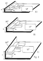
In den Fig. 2A bis 2C wird beispielhaft das Einlagern unterschiedlich großer Stückgüter 1 erläutert. In Fig. 2A ist eine Schublade 12' dargestellt, deren Blende 20 nur eine geringe Höhe a hat. Daraus ergibt sich, daß die Stückgüter 1 in dieser Schublade nur so gelagert werden können, daß ihr in Höhenrichtung der Schublade 12' gemessenes Maß ap kleiner als die Höhe a der Blende 20 ist. Der Rechner, dem die Abmessungen der Schublade 12' bekannt sind, ermittelt somit die Position des Stückgutes 1 so, daß es in dieser Schublade 12' gelagert werden kann. So ist erkennbar, daß das Stückgut 1' in der Schublade 12' nur so abgelegt werden kann, daß es mit seiner Breitseite auf der Schubladenfläche liegt. Hochkant kann das Stückgut 1' in dieser Schublade 12' nicht gelagert werden. Dementsprechend sind auch die schematisch in Fig. 2A dargestellten weiteren Stückgüter so abgelegt, daß ihre in vertikaler Richtung gemessenen Maße geringer sind als das Maß a der Blende 20.2A to 2C, the storage of items of
Fig. 2B zeigt eine Schublade 12'', deren Blende 20'' die Höhe b hat, die größer ist als die Höhe a der Blende 20 gemäß Fig. 2A. Dementsprechend können in dieser Schublade 12'' größere Stückgüter 1 gelagert werden. Auch sie müssen aber so in der Schublade 12'' abgelegt werden, daß ihre in vertikaler Richtung gemessenen Abmessungen ap kleiner sind als die Höhe b der Blende 20''. Die Greifeinrichtung des Portalroboters 3 wird durch den Rechner wiederum so gesteuert, daß das Stückgut so in der Schublade 2'' abgelegt wird, daß es nicht über die Blende 20'' übersteht.FIG. 2B shows a
Die Schublade 12''' gemäß Fig. 2C schließlich hat die größte Höhe c. Darum können in ihr die größten Stückgüter untergebracht werden. Auch hier müssen die Stückgüter so abgelegt werden, daß ihr in Vertikalrichtung gemessenes Maß ap geringer ist als die Höhe c der Blende 20'''.Finally, the drawer 12 '''according to FIG. 2C has the greatest height c. That is why the largest general cargo can be accommodated in it. Here, too, the piece goods must be placed in such a way that their dimension a p measured in the vertical direction is less than the height c of the diaphragm 20 '''.
Wie sich aus den Fig. 2A bis 2C ergibt, werden die Stückgüter nicht alphabetisch oder nach Warengruppen abgelegt, wie dies üblicherweise der Fall ist. Ablageprinzip ist ausschließlich die Packungsgröße bzw. die belegte Lagerfläche des Stückgutes 1. Der Rechner kann aus den Abmessungen der jeweiligen Schubladen die Lagerfläche bzw. das Lagervolumen berechnen und die anfallenden Stückgüter so den einzelnen Schubladen zuordnen, daß eine optimale Flächennutzung mit den Stückgütern gewährleistet ist. Da der Rechner die Art des Produktes, dessen Namen, dessen Größe und auch dessen Lagerstelle in der jeweiligen Schublade kennt, ist gewährleistet, daß der Apotheker jederzeit auf Abruf das erforderliche Präparat in noch zu beschreibender Weise automatisch erhält. Mit der Greifeinrichtung des Portalroboters 13 lassen sich die einzelnen Stückgüter auch einfach an bereits lagernde Packungen bei optimaler Flachennutzung in der jeweiligen Schublade ablegen.As can be seen from FIGS. 2A to 2C, the piece goods are not stored alphabetically or according to product groups, as is usually the case. The storage principle is exclusively the package size or the occupied storage area of the
Mit der beschriebenen Vorrichtung und dem beschriebenen Verfahren wird es möglich, auf einer vorgegebenen Grundfläche ein maximales Lagervolumen durch die Übereinanderanordnung möglichst vieler Lagerflächen zu erreichen. Dazu ist es erforderlich, den Abstand zwischen den Lagerstellen zu minimieren. Zu diesem Zweck wird die jeweils kleinste Seitenlänge des Stückgutes 1 als Höhenmaß herangezogen, so daß dementsprechend die jeweils größeren Seitenlängen die Lagerfläche des Stückgutes bilden. Auf diese Weise können die Lagerstellen niedriger Schubladen optimal ausgenutzt werden. Sollten die Lagerstellen der niedrigen Schubladen belegt sein, wird das Stückgut, das an und für sich für eine niedrige Schublade vorgesehen ist, in einer höheren Schublade unter Ausnutzung einer möglicherweise kleineren Lagerstelle abgelegt.With the described device and the described method it is possible to achieve a maximum storage volume on a given base area by arranging as many storage areas as possible on top of one another. This requires minimizing the distance between the bearing points. For this purpose, the smallest side length of the piece good 1 is used as the height dimension, so that the larger side lengths form the bearing surface of the piece goods. In this way, the storage locations of low drawers can be optimally used. If the storage locations of the low drawers are occupied, the general cargo, which in itself is a low drawer is provided, stored in a higher drawer using a possibly smaller storage location.
Im folgenden wird beispielhaft eine Flächenbedarfsermittlung für das Lager 11 beschrieben. Hierbei wird davon ausgegangen, daß in einer Apotheke durchschnittlich 8000 Artikel erhältlich sind. Diese Artikel können in Kategorien 1 bis 5 hinsichtlich ihrer Stückzahl in einer Apotheke eingeteilt werden. In die Kategorie 1 fallen Artikel, die der Apotheker beispielsweise 30 mal zur Verfügung hat (30 Einheiten). Durchschnittlich sind dies 0,5 % der angenommenen 8000 Artikel. Hieraus ergibt sich, daß der Apotheker 1200 dieser Artikel (Stückgüter) in der Apotheke zur Verfügung hat. In der Kategorie 2 sind durchschnittlich 15 Einheiten des Artikels vorhanden. Die Kategorie 2 macht durchschnittlich 1 % der 8000 Artikel aus, so daß sich in der Apotheke ebenfalls 1200 Stück dieser Artikel befinden (80 x 15). Die Kategorie 3 umfaßt solche Artikel, die der Apotheker durchschnittlich 5 mal auf Lager hat. Diese Kategorie 3 macht durchschnittlich 2 % der 8000 Artikel aus, woraus sich eine Stückzahl von 800 (160 x 5) ergibt. Die Kategorie 4, zu der solche Artikel zählen, die der Apotheker durchschnittlich nur zweimal auf Lager hat, macht etwa 5 % der Gesamtartikel aus. Somit ergibt sich für die Kategorie 4 eine Stückzahl von 800 (400 x 2). 91,5 % der 8000 Artikel fallen in die Kategorie 5, d.h. der Apotheker hat diese Produkte nur einmal auf Lager. Somit beträgt die Stückzahl der Kategorie 5 7320 (7320 x 1). Berücksichtigt man alle Kategorien 1 bis 5, so ergibt dies eine Artikelzahl von 11320, d.h. der Apotheker muß durchschnittlich diese Stückzahl in seinem Lager unterbringen.An area requirement determination for the
Werden die beiden größeren Seiten einer quaderförmigen Packung (Stückgut) als Lagerflächenseiten herangezogen, dann ergibt sich eine durchschnittliche Flächengröße pro Produkt von 5 cm x 7 cm = 35 cm². Wird hierzu noch beispielsweise jeweils ein 4 mm breiter Zwischenraum zur nächsten Packung als Greifraum hinzugerechnet, ergibt sich eine Fläche von 46 cm². Weiter muß ein durchschnittlicher Flächenverlust bei der Lagerungsoptimierung von beispielsweise 15 % berücksichtigt werden. Daraus ergibt sich eine durchschnittliche Flächengröße von 53 cm². Die 11320 Artikel beanspruchen somit eine Gesamtlagerfläche von 53 cm² x 11320 ≈ 60 m². In einer Apotheke durchschnittlicher Größe muß darum eine solche Lagerfläche von 60 m² zur Verfügung stehen.If the two larger sides of a cuboid pack (piece goods) are used as storage surface sides, this results in an average surface area per product of 5 cm x 7 cm = 35 cm². If, for example, a 4 mm wide space is added to the next pack as a gripping space, this results in an area of 46 cm². Furthermore, an average loss of area in the storage optimization of, for example, 15% must be taken into account. This results in an average area of 53 cm². The 11320 articles therefore occupy a total storage area of 53 cm² x 11320 ≈ 60 m². In a pharmacy of average size, such a storage area of 60 m² must be available.
Aus diesem Lagerflächenbedarf läßt sich sehr einfach eine Nutzhöhenbedarfsermittlung für das Lager 11 berechnen. Hierbei wird die kleinste Kantenlänge einer Packung 1 als Parameter herangezogen. Bei der folgenden Berechnung wird angenommen, daß die 11320 Stückgüter gleichmäßig in 32 Schubladen 12 mit jeweils einer Grundfläche von 2 m² verteilt eingelagert werden. Die Schubladen 12 sollen in fünf Typen A bis E unterteilt sein, wobei der Schubladentyp A ein Höhenrastermaß von 45 mm, der Schubladentyp B von 60 mm, der Schubladentyp C von 75 mm, der Schubladentyp D von 90 mm und der Schubladentyp E von 110 mm hat. Dieses Höhenrastermaß ergibt sich aus dem Nutzmaß sowie einer Zulage von 30 mm für die Konstruktion der Schublade, den lichten Abstand sowie für ein Vakuumbodensystem in den Schubladen, das unten noch näher erläutert werden soll. Zieht man dieses Zumaß von 30 mm ab, dann steht eine Nutzhöhe bei den Schubladentypen A bis E von 15 mm bis 80 mm zur Verfügung. Die Verpakkungsgrößen in einer Apotheke können sich beispielsweise wie folgt aufteilen:
55 % haben eine kleinste Kantenlänge von 15 mm
20 % haben eine kleinste Kantenlänge von 15 bis 30 mm
15 % haben eine kleinste Kantenlänge von 30 bis 45 mm
8 % haben eine kleinste Kantenlänge von 45 bis 60 mm
2 % haben eine kleinste Kantenlänge von 60 bis 80 mm
Umgerechnet auf eine Gesamtstückzahl von 11320 ergibt sich somit folgende Präparateanzahl:
55 % 6226
20 % 2264
15 % 1700
8 % 906
2 % 227.A usable height requirement determination for the
55% have a minimum edge length of 15 mm
20% have a minimum edge length of 15 to 30 mm
15% have a minimum edge length of 30 to 45 mm
8% have a minimum edge length of 45 to 60 mm
2% have a minimum edge length of 60 to 80 mm
Converted to a total number of 11320, the following number of preparations results:
55% 6226
20% 2264
15% 1700
8% 906
2% 227.
Diejenigen Präparate, die eine kleinste Kantenlänge von bis zu 15 mm haben, lassen sich im Schubladentyp A unterbringen. Entsprechend lassen sich die Präparate mit einer kleinsten Kantenlänge von 15 bis 30 mm im Schubladentyp B, von 30 bis 45 mm im Schubladentyp C, von 45 bis 60 mm im Schubladentyp D und von 60 bis 80 mm im Schubladentyp E unterbringen. Daraus ergibt sich unter Berücksichtigung der durchschnittlichen Flächengröße der Produkte von 53 cm² folgende benötigte Lagerfläche in den verschiedenen Schubladentypen:
- Schubladentyp A: 6226 Packungen x 53 cm² = 33 m² Schubladenfläche bei 45
mm Rasterhöhe 17 Schubladen - Schubladentyp B: 2264 Packungen x 53 cm² = 12 m² Schubladenfläche bei 60
mm Rasterhöhe 6 Schubladen - Schubladentyp C: 1700 Packungen x 53 cm² = 9 m² Schubladenfläche bei 75
mm Rasterhöhe 5 Schubladen - Schubladentyp D: 906 Packungen x 53 cm² = 4,8 m² Schubladenfläche bei 90 mm Rasterhöhe 3 Schubladen
- Schubladentyp E: 227 Packungen x 53 cm² = 1,2 m² Schubladenfläche bei 110
mm Rasterhöhe 1 Schublade.
- Drawer type A: 6226 packs x 53 cm² = 33 m² drawer surface with 45
mm grid height 17 drawers - Drawer type B: 2264 packs x 53 cm² = 12 m² drawer surface with 60
mm grid height 6 drawers - Drawer type C: 1700 packs x 53 cm² = 9 m² drawer surface with 75
mm grid height 5 drawers - Drawer type D: 906 packs x 53 cm² = 4.8 m² drawer surface with 90 mm grid height 3 drawers
- Drawer type E: 227 packs x 53 cm² = 1.2 m² drawer surface with 110
mm grid height 1 drawer.
Die Schubladenflächen ergeben somit eine Gesamtfläche von 60 m². Aus der Rasterhöhe und der Schubladenfläche ergibt sich somit ein Nettokonstruktionsvolumen der Schubladen von 3,44 m³.The drawer surfaces thus result in a total area of 60 m². The grid height and the drawer area thus result in a net construction volume of the drawers of 3.44 m³.
Auf diese Weise kann das Lager 11 optimal zur Lagerung der unterschiedlichsten Stückgüter 1 genutzt werden. Mit der Erfassungseinrichtung 4 wird das Stückgut 1 identifiziert. Anhand der Vermessung des Stückgutes 1 in der Vermessungseinrichtung 9 berechnet der Rechner unter Berücksichtigung des freien Lagerplatzes im Lager 11, in welcher Lage das Stückgut 1 in der jeweiligen Schublade 12 untergebracht werden kann, um eine optimale Flächenausnutzung zu ermöglichen. Dementsprechend wird die Greifeinrichtung des Portalroboters 13 gesteuert, damit sie das Stückgut 1 von der Transporteinrichtung 2 abnehmen und in der richtigen Lage an der ausgewählten Lagerstelle ablegen kann. Als Ordnungsmaßstab dient somit nicht mehr beispielsweise der Produktname oder die Produktart, sondern ausschließlich die Packungsgröße. Dadurch kann der Lagerraum erheblich verringert werden im Vergleich zur herkömmlichen Lagerung solcher Produkte, die ohne Rücksicht auf die Packungsgröße lediglich alphabetisch nach dem Produktnamen oder nach der Zusammengehörigkeit von Produktart bzw. Produktsorte gelagert werden. Da die Lagerung vollständig rechnergesteuert und vollautomatisch erfolgt, ist jederzeit sichergestellt, daß der Apotheker das von ihm gewünschte Produkt zuverlässig erhält. Er ist an seiner Verkaufstheke mit einer entsprechenden Computereinheit ausgestattet, die an den Rechner direkt oder beispielsweise ferngesteuert angeschlossen ist. Über sie gibt der Apotheker die entsprechenden Befehle oder Namen ein, damit ein entsprechendes Produkt aus dem Lager 11 geholt wird. Der zentrale Rechner gibt dann ein entsprechendes Signal an die Greifeinrichtung sowie an die Steuerung der einzelnen Schubladen 12, so daß diese ausfahren und die Greifeinrichtung das angeforderte Stückgut 1 ergreifen und entnehmen kann.In this way, the
Es ist auch möglich, den Abstand zwischen den Ablagen zu verändern, so daß eine Anpassung an das größte Höhenmaß des Stückgutes 1 möglich ist. Die Ablageflächen können hierzu vertikal verschiebbar angeordnet sein.It is also possible to change the distance between the shelves, so that an adaptation to the greatest height dimension of the
Damit beim Verschieben der Schubladen 12 das darin gelagerte Stückgut nicht verrutscht, sind sie mit einer Rutschsicherung versehen. Sie kann eine rutschfeste Oberseite des Bodens 21 der Schublade sein. Im dargestellten Ausführungsbeispiel werden die Stückgüter mittels Unterdruck gegen Verrutschen gesichert. Hierzu ist der Boden 21 (Fig. 3) der jeweiligen Schublade 12 mit Öffnungen 22 versehen, durch die Luft angesaugt werden kann. Die Verpackungen werden dadurch gegen den Schubladenboden 21 mittels Unterdruck gezogen, so daß sie beim Ein- und Ausfahren der Schublade 12 nicht verrutschen. Hierfür reicht ein verhältnismäßig geringer Unterdruck aus, der in herkömmlicher Weise mit Pumpen und dergleichen erzeugt werden kann. Im Bereich unterhalb des Bodens 21 ist die Schublade 12 mit einer entsprechenden Saugkammer versehen, aus der zur Erzeugung des Unterdruckes in bekannter Weise Luft abgesaugt wird.So that the piece goods stored therein do not slip when the
Damit die vom Apotheker gewünschten Präparate vom Lager 11 zur Verkaufsstelle transportiert werden, ist eine (nicht dargestellte) Warentransporteinrichtung vorgesehen, die das ausgewählte Produkt vorteilhaft unmittelbar bis an die Verkaufstheke heranfördert. Diese Warentransporteinrichtung hat beispielsweise ein Förderband, auf dem der Portalroboter 13 das jeweilige Stückgut 1 ablegt. Die Breite dieses Förderbandes ist auf die kürzeste Seitenlänge des Stückgutes 1 mit der größten kürzesten Seite abgestimmt. Vorteilhaft ist das Förderband U-förmig ausgebildet, so daß das Stückgut nicht vom Förderband fallen kann.So that the preparations desired by the pharmacist are transported from the
Das Förderband ist vorteilhaft in einem Rohr untergebracht, das zweckmäßig im Deckenbereich verläuft. Dieses Rohr kann oberhalb einer abgehängten Decke angeordnet sein, so daß es von außen nicht sichtbar ist. Dieses Transportrohr wird so geführt, daß es vom Arbeitsbereich des Portalroboters 13 bis zu einem Fallrohr 23 verläuft (Fig. 4), das sich beispielsweise bis zur Verkaufstheke erstreckt. Am Eintritt in das Fallrohr oder noch innerhalb des Transportrohres ist vorteilhaft eine Lichtschranke oder dergleichen eingebaut, mit der die Ankunft einer Packung festgestellt werden kann. Dann kann ein entsprechendes Signal im Verkaufsraum ausgelöst werden. Anstelle des beschriebenen Förderbandes können beispielsweise auf Schienen oder auf andere Weise geführte, miniaturisierte fahrerlose Transportsysteme eingesetzt werden.The conveyor belt is advantageously accommodated in a tube which expediently runs in the ceiling area. This tube can be arranged above a suspended ceiling, so that it is not visible from the outside. This transport pipe is guided in such a way that it runs from the working area of the
Damit das Stückgut 1 nicht ungebremst durch das Fallrohr 23 nach unten fällt, ist es mit einer Bremseinrichtung versehen. Das Fallrohr 23 hat vorzugsweise kreisförmigen Querschnitt. Zur Bildung der Bremseinrichtung sind in das Fallrohr 23 zwei dehnbare Trennwände 24 und 25 eingesetzt, die parallel zueinander verlaufen und zwischen sich einen Förderkanal 26 für das Stückgut 1 bilden. Zwischen den Trennwänden 24, 25 und dem Fallrohr 23 werden im Querschnitt segmentförmige Luftkammern 27 und 28 gebildet, in die Luftzuleitungen 29 und 30 münden. Über sie wird dosiert Luft in die Kammern 27, 28 geblasen, wobei die Trennwände 24, 25 entsprechend dem Luftdruck elastisch gedehnt werden. Das durch den Kanal 26 fallende Stückgut 1 dehnt die Trennwände 24, 25 beim Durchfallen geringfügig gegen den Druck in den Kammern 27, 28 und wird somit gebremst. Der Druck in den Kammern 27, 28 wird so an das durchfallende Stückgut angepaßt, daß es mit einer ausreichenden Geschwindigkeit nach unten fällt.So that the
Die Fallgeschwindigkeit kann sehr einfach beispielsweise durch zwei einander gegenüberliegende, an der Innenwandung des Fallrohres 23 im Förderkanal 26 sitzende Fotosensoren 31, 32 bestimmt werden. Ist die Fallgeschwindigkeit zu hoch, dann wird über die Luftzuleitungen 29, 30 Luft in die Kammern 27, 28 geleitet, wodurch die Trennwände 24, 25 mehr gedehnt werden (gestrichelte Linien in Fig. 4) und der Durchlaßquerschnitt des Kanals 26 verringert wird. Das Stückgut 1 wird auf diese Weise in seiner Fallgeschwindigkeit verringert.The falling speed can be determined very easily, for example, by two
Ist umgekehrt die Fallgeschwindigkeit zu gering, dann wird der Druck in den Kammern 27, 28 entsprechend verringert.Conversely, if the falling speed is too low, the pressure in the
Bei einer anderen (nicht dargestellten) Ausführungsform besteht die Bremseinrichtung aus zwei ineinander liegenden Schläuchen, die vorteilhaft aus einer glatten Folie gebildet sind. Der Innendurchmesser des inneren Schlauches wird an die Größe des Stückgutes 1 angepaßt. In den Ringraum zwischen den beiden Schläuchen wird dosiert Luft geblasen oder abgesaugt. Dadurch läßt sich der Innendurchmesser des inneren Schlauches einfach an die Größe und an das Gewicht des Stückgutes 1 anpassen. Das Stückgut 1 rutscht im inneren Schlauch gebremst nach unten. Der Innendurchmesser des inneren Schlauches ist geringfügig kleiner als die Packungsgröße. Aufgrund des Luftpolsters im Ringraum zwischen den beiden Schläuchen wird beim Hindurchfallen des Stückgutes 1 der innere Schlauch entsprechend geringfügig aufgeweitet. Lichtschranken im Fallrohr können wiederum die Fallgeschwindigkeit des Produktes verfolgen und über den Rechner bedarfsgerecht die Luftbremsung dosieren.In another (not shown) embodiment, the braking device consists of two hoses lying one inside the other, which are advantageously formed from a smooth film. The inner diameter of the inner tube is adapted to the size of the
Das Fallrohr kann auch innen mit Klappen versehen sein, die elektromagnetisch geladen werden können. Durch Dosierung des Stroms kann die Durchrutschgeschwindigkeit des Stückgutes 1 bestimmt werden. Diese elektromagnetische Variante erlaubt somit ebenfalls ein gebremstes Fördern des Stückgutes 1 im nach unten sich erstreckenden Fallrohr.The downpipe can also be provided on the inside with flaps that can be charged electromagnetically. The slipping speed of the
Das Stückgut kann aus dem Fallrohr in eine Aufnahme gefördert werden, aus welcher der Apotheker das Stückgut bequem herausnehmen kann. Es ist aber auch möglich, das Stückgut innerhalb des Fallrohres festzuhalten. Hierzu ist im Fallrohr ein quer zur Achse des Fallrohres bewegliches Klemmstück vorgesehen, das durch Strombeaufschlagung verstellt werden kann. Diesem Klemmstück gegenüber kann ein Widerlager im Fallrohr angeordnet sein. Rutscht das Stückgut 1 im Fallrohr nach unten, dann kann kurz vor dem Klemmstück eine Lichtschranke oder dergleichen vorgesehen sein. Passiert das Stückgut 1 diese Lichtschranke, wird ein Impuls ausgelöst, mit dem der Antrieb des Klemmstückes eingeschaltet wird. Es wird dann in Richtung auf das gegenüberliegende Widerlager verschoben, wodurch das Stückgut 1 zwischen ihm und dem Widerlager festgeklemmt wird. Das Fallrohr kann in Höhe dieser Klemmeinrichtung eine Klappe oder dergleichen aufweisen, so daß das Stückgut entnommen werden kann.The general cargo can be conveyed from the downpipe into a receptacle from which the pharmacist can conveniently remove the general cargo. However, it is also possible to hold the piece goods within the downpipe. For this purpose, a clamping piece which is movable transversely to the axis of the downpipe is provided in the downpipe and can be adjusted by applying current. Opposite this clamp an abutment can be arranged in the downpipe. If the
Eine solche Klemmeinrichtung kann aber auch in einem Transportwagen oder dergleichen vorgesehen sein, der sich unterhalb des Fallrohres befindet. Dann kann der Transportwagen unter dem Fallrohr weggefahren werden, so daß sich das Stückgut bequem entnehmen läßt.Such a clamping device can also be provided in a trolley or the like, which is located below the downpipe. Then the trolley can be moved away under the downpipe so that the general cargo can be removed easily.
Aufgrund der vollautomatischen Lagerung ist es vorteilhaft möglich, die abgelegten Stückgüter 1 umzulagern, um eine Optimierung der Lagerstellen zu gewährleisten. Eine solche Umlagerung wird zweckmäßig während der Ruhepausen in der Apotheke, bsp. in der Mittagspause oder über Nacht, durchgeführt, so daß der Apothekenbetrieb nicht gestört wird.Due to the fully automatic storage, it is advantageously possible to relocate the stored
Wird bei der Vermessung des Stückgutes 1 festgestellt, daß es in seinen Abmessungen zu groß ist und darum nicht in die im Lager 11 vorgesehenen Schubladen gelegt werden kann, wird ein entsprechendes Signal an den Rechner geschickt, der dann seinerseits ein Signal an das Handhabungsgerät 13 oder ein anderes Handhabungsgerät sendet, um das zu große Stückgut 1 auszusortieren. Auch ist es möglich, insbesondere wenn die Vermessung des Stückgutes 1 während des Transportes erfolgt, im Transportweg eine Sortierweiche vorzusehen, mittels der das zu große Stückgut 1 einfach aussortiert werden kann.If it is determined during the measurement of the
Mit der beschriebenen Einrichtung ist auch eine Wareneingangskontrolle sehr einfach möglich. Die ankommenden Stückgüter werden in der beschriebenen Weise auf die Transporteinrichtung 2 geschüttet und mittels der Vereinzelungseinheit 3 vereinzelt. Dann durchläuft jedes einzelne Stückgut die Erfassungseinrichtung 4, in der jedes einzelne Stückgut zuverlässig erfaßt wird. Der Rechner kann dann die übermittelten Werte mit einer Wareneingangsliste vergleichen, so daß mühelos eine Wareneingangskontrolle gewährleistet ist.With the described device, an incoming goods inspection is also very easy. The incoming piece goods are poured onto the
Gleichzeitig ist es möglich, das sogenannte "first in - first out"-Verfahren zu gewährleisten. Damit wird das älteste gelagerte bzw. eingegangene Stückgut eines Artikels auch als erstes entnommen.At the same time, it is possible to guarantee the so-called "first in - first out" process. This means that the oldest stored or received general cargo of an article is also removed first.
In der Erfassungseinrichtung 4 kann auch das an der Verpackung des Stückgutes 1 vorhandene Verfallsdatum erfaßt und dem Rechner mitgeteilt werden. Dieses Verfallsdatum kann dann als Kriterium für die Herausgabe des Stückgutes 1 aus dem Lager 11 dienen. Wird ein Stückgut 1 vom Apotheker angefordert, das mehrfach im Regal 11 vorhanden ist, dann weist der Rechner das Handhabungsgerät 13 an, das vom Verfallsdatum her älteste Stückgut 1 dem Lager 11 zu entnehmen und dem Apotheker in der beschriebenen Weise zuzuführen. Dem Rechner ist die Lagerstelle aufgrund der beschriebenen Erfassung bekannt, so daß der Rechner auch darüber informiert ist, welches Verfallsdatum das jeweilige Produkt hat. Somit hat der Apotheker die Gewähr dafür, daß das jeweils älteste Stückgut einer Sorte dem Lager 11 entnommen wird. Dadurch wird auch gewährleistet, daß das Verfallsdatum nicht oder nur in wenigen Fällen, wenn beispielsweise das Produkt nicht vom Kunden gekauft wird, verfällt. Ebenso ist es möglich, alle vom Verfall bedrohten Stückgüter nach Bedarf oder automatisch auszusortieren.The expiry date on the packaging of the
Schließlich ist in der beschriebenen Weise ohne weiteres eine vollautomatische Inventur möglich, da aus dem Rechner jederzeit der augenblickliche Warenbestand abgerufen werden kann. Darum entfällt für den Apotheker der sehr zeitaufwendige Inventurvorgang; er kann nunmehr automatisch vom Rechner vorgenommen werden. Er kann so programmiert sein, daß er eine entsprechende Inventurliste mit Angabe der jeweiligen Präparate, der Zahl der Präparate und dgl. ausdruckt.Finally, a fully automatic inventory is easily possible in the manner described, since the current inventory can be called up from the computer at any time. Therefore, the very time-consuming inventory process is no longer necessary for the pharmacist; it can now be carried out automatically by the computer. It can be programmed so that it prints a corresponding inventory list with details of the respective preparations, the number of preparations and the like.
Anstelle der beschriebenen rechnergestützten automatischen Vermessung und Identifizierung, welche die bevorzugte Vorgehensweise ist, ist es aber auch möglich, die Stückgüter 1 von Hand über eine optische Lese- und Vermessungseinrichtung zu führen. Diese Einrichtungen geben dann entsprechende Signale an den Rechner. Die Bedienungsperson legt anschließend die Stückgüter beispielsweise auf eine Transporteinrichtung, von der sie in der beschriebenen Weise von einem Handhabungsgerät abgenommen und eingelagert werden. Auch können die Stückgüter von Hand eingelagert werden, wie beschrieben worden ist.Instead of the described computer-assisted automatic measurement and identification, which is the preferred procedure, it is also possible to guide the
Die Stückgüter 1 können aber auch von Hand vermessen und/oder identifiziert werden. Die ermittelten Daten werden dann über eine Tastatur in den Rechner gegeben. Er ermittelt die für das jeweilige Stückgut optimale Lagerstelle. Die Ablage des Stückgutes erfolgt, wie zuvor im einzelnen beschrieben.The
Es ist auch eine Ausführungsform möglich, bei der die Stückgüter 1 nicht mittels des Handhabungsgerätes, sondern manuell eingelagert oder herausgenommen werden. Damit die Bedienungsperson die vom Rechner ermittelte Lagerstelle erkennt, sind verschiedene Einrichtungen möglich. So kann der Rechner eine Zeigereinrichtung steuern, die mit einem Lichtzeiger arbeitet, der die gewählte Lagerstelle anleuchtet.An embodiment is also possible in which the
Die Schubladen oder andere Ablagen können mit Leuchtanzeigen, beispielsweise LEDs, ausgestattet sein, die vom Rechner angesteuert werden. So kann jede Schublade an ihrer Blende mit einer Leuchtanzeige versehen sein, so daß die Bedienungsperson am Aufleuchten der entsprechenden Leuchtanzeige einfach erkennen kann, welche Schublade zum Ablegen des jeweiligen Stückgutes 1 vorgesehen ist. Um nun in der Schublade die entsprechende Lagerstelle zu kennzeichnen, kann der Schubladenboden mit in zueinander senkrecht liegenden Reihen von Leuchtanzeigen versehen sein, die in einem geeigneten Rasterabstand voneinander angeordnet sind. Durch Aufleuchten der entsprechenden Anzeigen wird die vom Rechner bestimmte Lagerstelle eindeutig angezeigt.The drawers or other shelves can be equipped with light indicators, for example LEDs, which are controlled by the computer. Thus, each drawer can be provided with a light indicator on its cover, so that the operator can easily see from the lighting of the corresponding light indicator which drawer is provided for storing the
Es ist aber auch möglich, daß die Lagerstelle in der Schublade nicht durch die Leuchtanzeigen, sondern durch einen Lichtzeiger angegeben wird, der vom Rechner gesteuert wird.But it is also possible that the storage location in the drawer is not indicated by the light indicators, but by a light pointer that is controlled by the computer.
Anstelle der beschriebenen bevorzugten Vereinzelung der Stückgüter 1 mittels der Vereinzelungseinheit 3 können die Stückgüter lediglich auf eine Ablage geschüttet werden. Wird als Lager ein Schubladenregal eingesetzt, dann kann als Ablage eine der Schubladen, vorzugsweise eine unterste Schublade, herangezogen werden. Sie wird vorteilhaft nach hinten ausgefahren, so daß die Stückgüter 1 wahllos in diese Schublade geschüttet werden können. Vorteilhaft werden die Stückgüter in der Schublade noch etwas verteilt. Die Schublade wird anschließend nach vorn ausgefahren. Die Greifeinrichtung des Handhabungsgerätes 13 ist mit einer optischen Erfassungseinrichtung versehen, die vorteilhaft eine Kamera ist. Sie ist vorzugsweise beweglich an der Greifeinrichtung angeordnet, so daß sie die in der Schublade befindlichen Stückgüter von mehreren Seiten erfassen kann. Mit einer solchen Erfassungseinrichtung kann das Stückgut vermessen und/oder identifiziert werden. Mit ihr ist es auch möglich, das Verfallsdatum zu lesen. Sollte das Stückgut ungünstig liegen, so daß beispielsweise der Barcode nicht lesbar ist, dann ergreift die Greifeinrichtung das Stückgut und dreht es so weit, daß der Barcode, das Verfallsdatum oder dgl. gelesen werden kann. Anschließend kann dieses Stückgut auf die beschriebene Weise abgelegt werden.Instead of the described preferred separation of the
Claims (20)
dadurch gekennzeichnet, daß als Lager für das Stückgut (1) ein Regal oder ein Schubladenlager (11) verwendet wird, in das die Stückgüter (1) nach der Vermessung und der Identifizierung unmittelbar eingelagert werden, daß als Meßgröße die Kantenlängen (ap) des Stückgutes (1) herangezogen werden, daß anhand der Meßgrößen diejenige Lagerstelle (12) ausgesucht wird, an der das jeweilige Stückgut (1) unter optimaler Flächenausnutzung des Lagers (11) abgelegt wird, daß die Lage der auf den Lagerstellen (12) abgelegten Stückgüter (1) mit dem Rechner erfaßt wird, und daß die Entnahme des jeweiligen Stückgutes (1) aus dem Lager (11) rechnergestützt durchgeführt wird.Method for storing general cargo at a storage location in a warehouse, in which the general cargo is measured and identified and then the measured general cargo size is fed as a signal to a computer that uses this signal to select a corresponding storage location,
characterized in that a shelf or a drawer storage (11) is used as a storage for the piece goods (1), in which the piece goods (1) are stored immediately after the measurement and identification, that the edge lengths (a p ) of the General cargo (1) are used so that the storage location (12) is selected on the basis of the measured variables at which the respective general cargo (1) is deposited with optimal use of the storage area (11), that the location of the general cargo stored on the storage locations (12) (1) is recorded with the computer, and that the removal of the respective piece goods (1) from the warehouse (11) is carried out with the aid of a computer.
dadurch gekennzeichnet, daß der Rechner ein Handhabungsgerät (13) steuert, mit dem das Stückgut (1) in der richtigen Lage auf der vom Rechner ausgesuchten Lagerstelle (12) abgelegt wird.Method according to claim 1,
characterized in that the computer is a handling device (13) controls with which the piece goods (1) are deposited in the correct position on the storage location (12) selected by the computer.
dadurch gekennzeichnet, daß als Meßgröße die kleinste Kantenlänge (ap) des Stückgutes (1) herangezogen wird.The method of claim 1 or 2,
characterized in that the smallest edge length (a p ) of the piece goods (1) is used as the measurement variable.
dadurch gekennzeichnet, daß die Stückgüter (1) unsortiert aufgegeben werden.Method according to one of claims 1 to 3,
characterized in that the piece goods (1) are given unsorted.
dadurch gekennzeichnet, daß die Stückgüter (1) während oder am Ende ihres Transportes, vorzugsweise mittels eines Barcodes oder durch OCR-Lesung, identifiziert werden.Method according to one of claims 1 to 4,
characterized in that the piece goods (1) are identified during or at the end of their transport, preferably by means of a bar code or by OCR reading.
dadurch gekennzeichnet, daß die Vermessung mechanisch und/oder optoelektronisch erfolgt.Method according to one of claims 1 to 5,
characterized in that the measurement is carried out mechanically and / or optoelectronically.
dadurch gekennzeichnet, daß die Vermessung elektrisch und/oder elektronisch erfolgt.Method according to one of claims 1 to 5,
characterized in that the measurement is carried out electrically and / or electronically.
dadurch gekennzeichnet, daß die Vermessung mit Ultraschall erfolgt.Method according to one of claims 1 to 5,
characterized in that the measurement is carried out with ultrasound.
dadurch gekennzeichnet, daß die Vorrichtung als Endlager wenigstens ein Regal- oder Schubladenlager (11) aufweist, das im Arbeitsbereich des Handhabungsgerätes (13) liegt, und daß im Arbeitsbereich des Handhabungsgerätes (13) mindestens eine Abgabeeinheit (23) liegt.Device for carrying out the method according to one of claims 1 to 8, with at least one detection and at least one measuring device, which are connected to at least one computer to which a handling device for the piece goods is connected and which has at least one interface via which an output signal characterizing the respective storage location in at least one warehouse can be output,
characterized in that the device has at least one shelf or drawer bearing (11) as the final storage, which lies in the working area of the handling device (13), and in that in the working area of the handling device (13) there is at least one delivery unit (23).
dadurch gekennzeichnet, daß das Handhabungsgerät (13) mindestens eine Greif- oder Saugeinrichtung aufweist.Device according to claim 9,
characterized in that the handling device (13) has at least one gripping or suction device.
dadurch gekennzeichnet, daß die Vermessungseinrichtung (9) und/oder die Identifikationseinrichtung stationär oder mobil angeordnet ist.Device according to claim 9 or 10,
characterized in that the measuring device (9) and / or the identification device is arranged stationary or mobile.
dadurch gekennzeichnet, daß die Vermessungseinrichtung (9) elektrische oder elektronische, vorzugsweise an den Rechner angeschlossene Meßsysteme (10) aufweist, wie optische Meßgeräte, Lichtschranken, Sensoren, CCD-Kameras, mit Ultraschall arbeitende Geräte und dergleichen, die das Stückgut (1) vorzugsweise in den drei Raumkoordinaten erfassen.Device according to one of claims 9 to 11,
characterized in that the measuring device (9) has electrical or electronic measuring systems (10), preferably connected to the computer, such as optical measuring devices, light barriers, sensors, CCD cameras, ultrasound devices and the like, which preferably carry the piece goods (1) in the three spatial coordinates.
dadurch gekennzeichnet, daß das Handhabungsgerät (13) ein Roboter, vorzugsweise ein Portalroboter, ist.Device according to one of claims 9 to 12,
characterized in that the handling device (13) is a robot, preferably a portal robot.
dadurch gekennzeichnet, daß die Lagerstellen (12) rechnergesteuert bewegbar, vorzugsweise ein- und ausfahrbar sind.Device according to one of claims 9 to 13,
characterized in that the bearing points (12) can be moved under computer control, preferably can be moved in and out.
dadurch gekennzeichnet, daß der Abstand zwischen den Lagerstellen (12) unterschiedlich, vorzugsweise veränderbar ist.Device according to one of claims 9 to 14,
characterized in that the distance between the bearing points (12) is different, preferably variable.
dadurch gekennzeichnet, daß die Lagerstellen (12) für die in ihnen gelagerten Stückgüter (1) eine Rutschsicherung aufweisen.Device according to one of claims 9 to 15,
characterized in that the bearing points (12) have an anti-slip device for the piece goods (1) stored in them.
dadurch gekennzeichnet, daß die Rutschsicherung durch eine rutschfeste Oberseite der Lagerstelle (12) gebildet ist.Device according to claim 16,
characterized in that the anti-slip device is formed by a non-slip upper side of the bearing point (12).
dadurch gekennzeichnet, daß die Rutschsicherung durch eine Ansaugeinrichtung gebildet wird, wobei im Boden (21) der Lagerstelle (12) Öffnungen (22) zum Ansaugen der Stückgüter (1) vorgesehen sind und die Lagerstelle (12) unterhalb des Bodens (21) mindestens eine Ansaugkammer aufweist.Device according to claim 16,
characterized in that the anti-slip device is formed by a suction device, openings (22) for sucking in the piece goods (1) being provided in the bottom (21) of the bearing point (12) and the bearing point (12) below the bottom (21) at least one Has suction chamber.
dadurch gekennzeichnet, daß sie mindestens eine Vereinzelungseinheit (3) für die Stückgüter (1) aufweist.Device according to one of claims 9 to 18,
characterized in that it has at least one separating unit (3) for the piece goods (1).
dadurch gekennzeichnet, daß die Erfassungseinrichtung (4) mindestens eine Leseeinrichtung (5 bis 8), vorzugsweise einen Scanner, aufweist.Device according to one of claims 9 to 19,
characterized in that the detection device (4) has at least one reading device (5 to 8), preferably a scanner.
Applications Claiming Priority (4)
| Application Number | Priority Date | Filing Date | Title |
|---|---|---|---|
| DE4311866 | 1993-04-10 | ||
| DE4311866 | 1993-04-10 | ||
| DE4318341A DE4318341B4 (en) | 1993-04-10 | 1993-06-02 | Method for storing pharmacy articles and device for carrying out such a method |
| DE4318341 | 1993-06-02 |
Publications (3)
| Publication Number | Publication Date |
|---|---|
| EP0620528A1 true EP0620528A1 (en) | 1994-10-19 |
| EP0620528B1 EP0620528B1 (en) | 1997-07-02 |
| EP0620528B2 EP0620528B2 (en) | 2001-10-31 |
Family
ID=25924836
Family Applications (1)
| Application Number | Title | Priority Date | Filing Date |
|---|---|---|---|
| EP94105359A Expired - Lifetime EP0620528B2 (en) | 1993-04-10 | 1994-04-07 | Method for storing parcels and apparatus for carrying out this method |
Country Status (4)
| Country | Link |
|---|---|
| US (1) | US5473545A (en) |
| EP (1) | EP0620528B2 (en) |
| AT (1) | ATE154984T1 (en) |
| ES (1) | ES2104219T5 (en) |
Cited By (10)
| Publication number | Priority date | Publication date | Assignee | Title |
|---|---|---|---|---|
| DE19505509A1 (en) * | 1995-02-10 | 1996-08-14 | Mannesmann Ag | Method and device for measuring the volume of a moving material |
| DE19610631A1 (en) * | 1996-03-11 | 1997-09-18 | Kht Kommissionier & Handhabung | Size measuring system for block-shaped goods being conveyed |
| DE19722066A1 (en) * | 1997-05-27 | 1998-12-03 | Smb Schwede Maschinenbau Gmbh | Strapping machine for strapping objects with an object height-dependent tensioning device |
| DE19915731A1 (en) * | 1999-04-08 | 2000-11-16 | Momac Ges Fuer Maschb Mbh & Co | Monitoring of moving objects of similar geometrical form, such as chain links or saw teeth, to ensure object spacing is maintained, by measuring time of passage of a unit and comparison with a pre- determined characteristic value |
| EP1748004A1 (en) * | 2005-07-28 | 2007-01-31 | ROWA AUTOMATISIERUNGSSYSTEME GMBH & CO. KG | Method and device for measuring and positioning a cuboidal piece of goods |
| EP2042448A1 (en) * | 2007-09-26 | 2009-04-01 | Metall- und Kunststoffwaren Erzeugungsgesellschaft m.b.H. | Grip system for a storage system and storage system |
| DE10008362B4 (en) * | 2000-02-17 | 2009-04-09 | Kht Kommissionier- Und Handhabungstechnik Gmbh | Shelf storage system, in particular for the picking of drug packages |
| EP2053550A1 (en) * | 2007-10-24 | 2009-04-29 | Rowa Automatisierungssysteme GmbH | Method for providing and storing drug dispenser packs |
| EP2119642A1 (en) | 2008-05-02 | 2009-11-18 | Rowa Automatisierungssysteme GmbH | Procedure for storing a number of cylindrical containers in an automatic racking facility and container carrier used for this |
| WO2020089177A1 (en) * | 2018-10-31 | 2020-05-07 | Ferag Ag | Storage device for storing transport units |
Families Citing this family (29)
| Publication number | Priority date | Publication date | Assignee | Title |
|---|---|---|---|---|
| US6071060A (en) * | 1998-04-08 | 2000-06-06 | Mcms, Inc. | Calibration jig for an automated placement machine |
| GB2339569A (en) * | 1998-07-16 | 2000-02-02 | Supply Point Systems Limited | Drawer access control |
| US6682156B2 (en) | 1998-07-16 | 2004-01-27 | Supply Point Systems Ltd. | Apparatus for controlling access to a plurality of drawers |
| DE19941640B4 (en) * | 1998-09-01 | 2009-04-02 | Kht Kommissionier- Und Handhabungstechnik Gmbh | Method for the computer-controlled storage of general cargo and an associated shelf storage system, in particular for the picking of medicament packs |
| DE19858158C2 (en) * | 1998-12-16 | 2002-04-18 | Holger Panitzek | Reading system assigned to a transport device |
| JP3484104B2 (en) * | 1998-12-25 | 2004-01-06 | 平田機工株式会社 | Automatic warehouse and automatic warehouse management method |
| US6449531B1 (en) * | 2000-08-25 | 2002-09-10 | Advanced Micro Devices, Inc. | System for batching integrated circuits in trays |
| NZ510133A (en) * | 2001-02-23 | 2004-01-30 | Internat Stevedoring Operation | 3-D modeling of cargo packing on a ship |
| US6615104B2 (en) | 2001-05-01 | 2003-09-02 | Nintendo Of America, Inc. | System and method of selecting box size |
| EP1273531A1 (en) * | 2001-07-02 | 2003-01-08 | Crisplant A/S | A storage system for storing items to be distributed |
| US6832129B2 (en) * | 2003-02-26 | 2004-12-14 | Mitsubishi Electric Research Laboratories, Inc. | Method for packing rectangular strips |
| US7266422B1 (en) * | 2004-04-09 | 2007-09-04 | Fanuc Robotics America, Inc. | Automated palletizing cases having mixed sizes and shapes |
| SE0402030L (en) * | 2004-08-16 | 2006-02-17 | Moving Ab | Stock management system and procedure |
| DE102005035262B4 (en) * | 2005-07-25 | 2007-12-20 | Modicos Kommisioniersysteme Gmbh | Shelf warehouse with input station |
| US7753191B2 (en) * | 2005-09-13 | 2010-07-13 | Crisplant A/S | System and method for automated handling of baggage objects |
| ITUD20050199A1 (en) * | 2005-11-24 | 2007-05-25 | Rgs Automazioni S R L | AUTOMATED WAREHOUSE AND RELATED STORAGE PROCEDURE |
| US20120072004A1 (en) * | 2005-12-23 | 2012-03-22 | Jorge Lopez-Carrasco Picado | Automatic mould stripping system |
| DE202006013956U1 (en) * | 2006-09-12 | 2008-01-31 | Gebr. Willach Gmbh | Receipt of goods Machine |
| US7551985B1 (en) * | 2006-10-30 | 2009-06-23 | Cadence Design Systems, Inc. | Method and apparatus for power consumption optimization for integrated circuits |
| GB2471964B (en) * | 2008-02-05 | 2012-02-08 | Baa Ip Holdco Ltd | Handling |
| EP2156914A1 (en) * | 2008-08-19 | 2010-02-24 | Arnout De Lille | A control system and associated method for cutting |
| US20100073476A1 (en) * | 2008-09-24 | 2010-03-25 | Industrial Technology Research Institute | Systems and methods for measuring three-dimensional profile |
| US8595363B2 (en) | 2011-04-07 | 2013-11-26 | Infosys Limited | System and method for fast server consolidation |
| US9725240B2 (en) * | 2013-03-14 | 2017-08-08 | Signode Industrial Group Llc | Storage system and methods |
| DE102013005615A1 (en) * | 2013-04-04 | 2014-10-09 | Atlantic C Handels- Und Beratungs-Gmbh | Method and device for loading a pallet |
| US20150130592A1 (en) * | 2013-11-13 | 2015-05-14 | Symbol Technologies. Inc. | Package-loading system |
| US9617074B2 (en) | 2015-09-08 | 2017-04-11 | Carefusion Germany 326 Gmbh | Method and picking device for storing a plurality of identical piece goods |
| ES2955080T3 (en) * | 2015-09-08 | 2023-11-28 | Becton Dickinson Rowa Germany Gmbh | Order picking device for storing a plurality of identical loose goods |
| DE102020127201B3 (en) * | 2020-10-15 | 2022-03-17 | WST Präzisionstechnik GmbH | Device for loading and unloading as well as for operating a machine vice |
Citations (3)
| Publication number | Priority date | Publication date | Assignee | Title |
|---|---|---|---|---|
| US4692876A (en) * | 1984-10-12 | 1987-09-08 | Hitachi, Ltd. | Automatic freight stacking system |
| EP0349433A1 (en) * | 1988-07-01 | 1990-01-03 | SOCIETE GENERALE POUR LES TECHNIQUES NOUVELLES S.G.N. Société anonyme dite: | Method and device for controlling stores |
| DE4026449A1 (en) * | 1990-08-21 | 1992-03-05 | Fraunhofer Ges Forschung | DEVICE FOR PALLETIZING AND / OR SORTING ITEMS |
Family Cites Families (7)
| Publication number | Priority date | Publication date | Assignee | Title |
|---|---|---|---|---|
| US5273392A (en) * | 1986-01-02 | 1993-12-28 | Computer Aided Systems, Inc. | Automated work center and method |
| US5050090A (en) * | 1989-03-30 | 1991-09-17 | R. J. Reynolds Tobacco Company | Object placement method and apparatus |
| US5175692A (en) * | 1989-04-14 | 1992-12-29 | University Of Cincinnati | Method and apparatus for palletizing randomly arriving mixed size and content parcels |
| DE8905526U1 (en) † | 1989-05-02 | 1989-06-29 | Copla Foerder- Und Lagertechnik Gesellschaft Fuer Anlagenbau Mbh, 1000 Berlin, De | |
| US5015145A (en) * | 1989-10-06 | 1991-05-14 | R. J. Reynolds Tobacco Company | Automated cargo loading system |
| NL9101213A (en) † | 1991-07-10 | 1993-02-01 | Nederland Ptt | METHOD FOR FILLING AN AREA WITH ARTICLES IN THE FORM OF A RECTANGULAR PARALLELEPIPEDUM |
| US5324156A (en) * | 1991-11-14 | 1994-06-28 | Keuro Besitz Gmbh & Co. Edv-Dienstleistungs Kg | Apparatus for storing and discharging rod-shaped workpieces |
-
1994
- 1994-04-07 ES ES94105359T patent/ES2104219T5/en not_active Expired - Lifetime
- 1994-04-07 EP EP94105359A patent/EP0620528B2/en not_active Expired - Lifetime
- 1994-04-07 AT AT94105359T patent/ATE154984T1/en active
- 1994-04-08 US US08/225,382 patent/US5473545A/en not_active Expired - Fee Related
Patent Citations (3)
| Publication number | Priority date | Publication date | Assignee | Title |
|---|---|---|---|---|
| US4692876A (en) * | 1984-10-12 | 1987-09-08 | Hitachi, Ltd. | Automatic freight stacking system |
| EP0349433A1 (en) * | 1988-07-01 | 1990-01-03 | SOCIETE GENERALE POUR LES TECHNIQUES NOUVELLES S.G.N. Société anonyme dite: | Method and device for controlling stores |
| DE4026449A1 (en) * | 1990-08-21 | 1992-03-05 | Fraunhofer Ges Forschung | DEVICE FOR PALLETIZING AND / OR SORTING ITEMS |
Non-Patent Citations (1)
| Title |
|---|
| "Automated Parts Handling System", IBM TECHNICAL DISCLOSURE BULLETIN., vol. 28, no. 1, June 1985 (1985-06-01), ARMONK US, pages 180 - 183 * |
Cited By (14)
| Publication number | Priority date | Publication date | Assignee | Title |
|---|---|---|---|---|
| DE19505509C2 (en) * | 1995-02-10 | 2003-01-30 | Siemens Ag | Method and device for measuring the volume of a moving material |
| DE19505509A1 (en) * | 1995-02-10 | 1996-08-14 | Mannesmann Ag | Method and device for measuring the volume of a moving material |
| DE19610631A1 (en) * | 1996-03-11 | 1997-09-18 | Kht Kommissionier & Handhabung | Size measuring system for block-shaped goods being conveyed |
| DE19722066A1 (en) * | 1997-05-27 | 1998-12-03 | Smb Schwede Maschinenbau Gmbh | Strapping machine for strapping objects with an object height-dependent tensioning device |
| US6003438A (en) * | 1997-05-27 | 1999-12-21 | Smb Schwede Maschinenbau Gmbh | Looping machine for the looping of objects comprising device for tensioning in dependence on the height of an object |
| DE19915731A1 (en) * | 1999-04-08 | 2000-11-16 | Momac Ges Fuer Maschb Mbh & Co | Monitoring of moving objects of similar geometrical form, such as chain links or saw teeth, to ensure object spacing is maintained, by measuring time of passage of a unit and comparison with a pre- determined characteristic value |
| DE10008362B4 (en) * | 2000-02-17 | 2009-04-09 | Kht Kommissionier- Und Handhabungstechnik Gmbh | Shelf storage system, in particular for the picking of drug packages |
| EP1748004A1 (en) * | 2005-07-28 | 2007-01-31 | ROWA AUTOMATISIERUNGSSYSTEME GMBH & CO. KG | Method and device for measuring and positioning a cuboidal piece of goods |
| EP2042448A1 (en) * | 2007-09-26 | 2009-04-01 | Metall- und Kunststoffwaren Erzeugungsgesellschaft m.b.H. | Grip system for a storage system and storage system |
| EP2053550A1 (en) * | 2007-10-24 | 2009-04-29 | Rowa Automatisierungssysteme GmbH | Method for providing and storing drug dispenser packs |
| EP2119642A1 (en) | 2008-05-02 | 2009-11-18 | Rowa Automatisierungssysteme GmbH | Procedure for storing a number of cylindrical containers in an automatic racking facility and container carrier used for this |
| WO2020089177A1 (en) * | 2018-10-31 | 2020-05-07 | Ferag Ag | Storage device for storing transport units |
| CN113195383A (en) * | 2018-10-31 | 2021-07-30 | 费拉格有限公司 | Storage device for storing in transport units |
| EP4219351A3 (en) * | 2018-10-31 | 2023-08-30 | Ferag AG | Storage device for storing transport units |
Also Published As
| Publication number | Publication date |
|---|---|
| EP0620528B2 (en) | 2001-10-31 |
| ES2104219T3 (en) | 1997-10-01 |
| EP0620528B1 (en) | 1997-07-02 |
| US5473545A (en) | 1995-12-05 |
| ES2104219T5 (en) | 2002-04-01 |
| ATE154984T1 (en) | 1997-07-15 |
Similar Documents
| Publication | Publication Date | Title |
|---|---|---|
| EP0620528B1 (en) | Method for storing parcels and apparatus for carrying out this method | |
| DE4318341B4 (en) | Method for storing pharmacy articles and device for carrying out such a method | |
| EP3254893B1 (en) | Delivery vehicle and method for delivering mail items to different locations along a delivery route | |
| DE10225332B4 (en) | Storage buffer and method for storing piece goods for an automated general cargo warehouse | |
| DE19927251C2 (en) | Device for handling piece goods | |
| DE102011116081B3 (en) | System and method for manual batch picking using the goods-to-man principle | |
| DE102009019511B3 (en) | Storage and picking system and method of operating the same in batch mode | |
| EP2186754B1 (en) | Picking system and method for operating same with a picking cart | |
| EP0847939B1 (en) | Method of order picking and device therefor | |
| EP3328759A1 (en) | Method and system for delivering items in delivery containers | |
| AT514162A1 (en) | Storage and picking system for fully automated recognition and order picking of articles | |
| DE4336885A1 (en) | Commissioning system for pharmacy products | |
| EP1686080A2 (en) | Commissioning area | |
| AT512338A1 (en) | PICKING STATION AND METHOD OF PICKING ARTICLES | |
| EP2761605A1 (en) | Apparatus for storing and fully automatically dispensing a multiplicity of products | |
| AT520945A1 (en) | Picking station and method for automatic picking of goods | |
| DE102012211977A1 (en) | Method and apparatus for transporting items from dispensing stations to receiving stations | |
| EP0645322B1 (en) | Method for distributing return articles in a mailer dispatchcenter, in particular of clothing | |
| DE19719651A1 (en) | Method and device for picking | |
| DE102019119356A1 (en) | Window conveyor technology, order picking system and manual order picking process | |
| DE102009052345B4 (en) | Automated picking device and method for automated picking of books, media, brochures and similar items | |
| EP3992117A1 (en) | Device and method for moving goods in an automatic goods storage | |
| EP1710174B1 (en) | Method for order picking of articles | |
| DE202008006941U1 (en) | Workplace for picking goods | |
| EP1445215B1 (en) | Storage device and method for storing articles |
Legal Events
| Date | Code | Title | Description |
|---|---|---|---|
| PUAI | Public reference made under article 153(3) epc to a published international application that has entered the european phase |
Free format text: ORIGINAL CODE: 0009012 |
|
| AK | Designated contracting states |
Kind code of ref document: A1 Designated state(s): AT BE CH DE ES FR GB IT LI NL SE |
|
| 17P | Request for examination filed |
Effective date: 19941111 |
|
| 17Q | First examination report despatched |
Effective date: 19951010 |
|
| GRAG | Despatch of communication of intention to grant |
Free format text: ORIGINAL CODE: EPIDOS AGRA |
|
| GRAH | Despatch of communication of intention to grant a patent |
Free format text: ORIGINAL CODE: EPIDOS IGRA |
|
| GRAH | Despatch of communication of intention to grant a patent |
Free format text: ORIGINAL CODE: EPIDOS IGRA |
|
| GRAA | (expected) grant |
Free format text: ORIGINAL CODE: 0009210 |
|
| AK | Designated contracting states |
Kind code of ref document: B1 Designated state(s): AT BE CH DE ES FR GB IT LI NL SE |
|
| REF | Corresponds to: |
Ref document number: 154984 Country of ref document: AT Date of ref document: 19970715 Kind code of ref document: T |
|
| REG | Reference to a national code |
Ref country code: CH Ref legal event code: NV Representative=s name: PATENTANWALTSBUERO JEAN HUNZIKER Ref country code: CH Ref legal event code: EP |
|
| REF | Corresponds to: |
Ref document number: 59403238 Country of ref document: DE Date of ref document: 19970807 |
|
| ITF | It: translation for a ep patent filed |
Owner name: INTERPATENT ST.TECN. BREV. |
|
| REG | Reference to a national code |
Ref country code: ES Ref legal event code: FG2A Ref document number: 2104219 Country of ref document: ES Kind code of ref document: T3 |
|
| GBT | Gb: translation of ep patent filed (gb section 77(6)(a)/1977) |
Effective date: 19970929 |
|
| ET | Fr: translation filed | ||
| PLBQ | Unpublished change to opponent data |
Free format text: ORIGINAL CODE: EPIDOS OPPO |
|
| PLBQ | Unpublished change to opponent data |
Free format text: ORIGINAL CODE: EPIDOS OPPO |
|
| PLBI | Opposition filed |
Free format text: ORIGINAL CODE: 0009260 |
|
| PLBF | Reply of patent proprietor to notice(s) of opposition |
Free format text: ORIGINAL CODE: EPIDOS OBSO |
|
| 26 | Opposition filed |
Opponent name: W.M.K. MASCHINENBAU R. WAGNER Effective date: 19980331 Opponent name: WESTFALIA WST SYSTEMTECHNIK GMBH & CO. KG Effective date: 19980328 |
|
| NLR1 | Nl: opposition has been filed with the epo |
Opponent name: MANNESMANN AG Opponent name: W.M.K. MASCHINENBAU R. WAGNER GMBH & CO. OHG Opponent name: WESTFALIA WST SYSTEMTECHNIK GMBH & CO. KG |
|
| PLBF | Reply of patent proprietor to notice(s) of opposition |
Free format text: ORIGINAL CODE: EPIDOS OBSO |
|
| PLAW | Interlocutory decision in opposition |
Free format text: ORIGINAL CODE: EPIDOS IDOP |
|
| APAC | Appeal dossier modified |
Free format text: ORIGINAL CODE: EPIDOS NOAPO |
|
| APAE | Appeal reference modified |
Free format text: ORIGINAL CODE: EPIDOS REFNO |
|
| APAC | Appeal dossier modified |
Free format text: ORIGINAL CODE: EPIDOS NOAPO |
|
| APAC | Appeal dossier modified |
Free format text: ORIGINAL CODE: EPIDOS NOAPO |
|
| PLAW | Interlocutory decision in opposition |
Free format text: ORIGINAL CODE: EPIDOS IDOP |
|
| ITF | It: translation for a ep patent filed |
Owner name: INTERPATENT ST.TECN. BREV. |
|
| PUAH | Patent maintained in amended form |
Free format text: ORIGINAL CODE: 0009272 |
|
| STAA | Information on the status of an ep patent application or granted ep patent |
Free format text: STATUS: PATENT MAINTAINED AS AMENDED |
|
| 27A | Patent maintained in amended form |
Effective date: 20011031 |
|
| AK | Designated contracting states |
Kind code of ref document: B2 Designated state(s): AT BE CH DE ES FR GB IT LI NL SE |
|
| GBTA | Gb: translation of amended ep patent filed (gb section 77(6)(b)/1977) | ||
| REG | Reference to a national code |
Ref country code: CH Ref legal event code: AEN Free format text: AUFRECHTERHALTUNG DES PATENTES IN GEAENDERTER FORM |
|
| REG | Reference to a national code |
Ref country code: GB Ref legal event code: IF02 |
|
| NLR2 | Nl: decision of opposition | ||
| REG | Reference to a national code |
Ref country code: ES Ref legal event code: DC2A Kind code of ref document: T5 Effective date: 20020114 |
|
| NLR3 | Nl: receipt of modified translations in the netherlands language after an opposition procedure | ||
| ET3 | Fr: translation filed ** decision concerning opposition | ||
| APAH | Appeal reference modified |
Free format text: ORIGINAL CODE: EPIDOSCREFNO |
|
| NLUE | Nl: licence registered with regard to european patents |
Effective date: 20051205 |
|
| NLUE | Nl: licence registered with regard to european patents |
Effective date: 20070323 |
|
| PGFP | Annual fee paid to national office [announced via postgrant information from national office to epo] |
Ref country code: FR Payment date: 20100520 Year of fee payment: 17 Ref country code: ES Payment date: 20100503 Year of fee payment: 17 |
|
| PGFP | Annual fee paid to national office [announced via postgrant information from national office to epo] |
Ref country code: NL Payment date: 20100430 Year of fee payment: 17 |
|
| PGFP | Annual fee paid to national office [announced via postgrant information from national office to epo] |
Ref country code: CH Payment date: 20100525 Year of fee payment: 17 Ref country code: BE Payment date: 20100521 Year of fee payment: 17 |
|
| PGFP | Annual fee paid to national office [announced via postgrant information from national office to epo] |
Ref country code: SE Payment date: 20100430 Year of fee payment: 17 Ref country code: GB Payment date: 20100505 Year of fee payment: 17 |
|
| PG25 | Lapsed in a contracting state [announced via postgrant information from national office to epo] |
Ref country code: IT Free format text: LAPSE BECAUSE OF NON-PAYMENT OF DUE FEES Effective date: 20100407 |
|
| PGFP | Annual fee paid to national office [announced via postgrant information from national office to epo] |
Ref country code: IT Payment date: 20100430 Year of fee payment: 17 |
|
| PGRI | Patent reinstated in contracting state [announced from national office to epo] |
Ref country code: IT Effective date: 20110616 |
|
| BERE | Be: lapsed |
Owner name: *SCHAUSTEN CHRISTOPH Effective date: 20110430 |
|
| REG | Reference to a national code |
Ref country code: NL Ref legal event code: V1 Effective date: 20111101 |
|
| REG | Reference to a national code |
Ref country code: SE Ref legal event code: EUG |
|
| REG | Reference to a national code |
Ref country code: CH Ref legal event code: PL |
|
| GBPC | Gb: european patent ceased through non-payment of renewal fee |
Effective date: 20110407 |
|
| REG | Reference to a national code |
Ref country code: FR Ref legal event code: ST Effective date: 20111230 |
|
| PG25 | Lapsed in a contracting state [announced via postgrant information from national office to epo] |
Ref country code: BE Free format text: LAPSE BECAUSE OF NON-PAYMENT OF DUE FEES Effective date: 20110430 Ref country code: FR Free format text: LAPSE BECAUSE OF NON-PAYMENT OF DUE FEES Effective date: 20110502 Ref country code: LI Free format text: LAPSE BECAUSE OF NON-PAYMENT OF DUE FEES Effective date: 20110430 Ref country code: NL Free format text: LAPSE BECAUSE OF NON-PAYMENT OF DUE FEES Effective date: 20111101 Ref country code: CH Free format text: LAPSE BECAUSE OF NON-PAYMENT OF DUE FEES Effective date: 20110430 |
|
| PG25 | Lapsed in a contracting state [announced via postgrant information from national office to epo] |
Ref country code: GB Free format text: LAPSE BECAUSE OF NON-PAYMENT OF DUE FEES Effective date: 20110407 |
|
| PGRI | Patent reinstated in contracting state [announced from national office to epo] |
Ref country code: IT Effective date: 20110616 |
|
| REG | Reference to a national code |
Ref country code: ES Ref legal event code: FD2A Effective date: 20120604 |
|
| PG25 | Lapsed in a contracting state [announced via postgrant information from national office to epo] |
Ref country code: ES Free format text: LAPSE BECAUSE OF NON-PAYMENT OF DUE FEES Effective date: 20110408 |
|
| PGFP | Annual fee paid to national office [announced via postgrant information from national office to epo] |
Ref country code: AT Payment date: 20120430 Year of fee payment: 19 |
|
| PG25 | Lapsed in a contracting state [announced via postgrant information from national office to epo] |
Ref country code: SE Free format text: LAPSE BECAUSE OF NON-PAYMENT OF DUE FEES Effective date: 20110408 |
|
| REG | Reference to a national code |
Ref country code: AT Ref legal event code: MM01 Ref document number: 154984 Country of ref document: AT Kind code of ref document: T Effective date: 20130430 |
|
| PG25 | Lapsed in a contracting state [announced via postgrant information from national office to epo] |
Ref country code: AT Free format text: LAPSE BECAUSE OF NON-PAYMENT OF DUE FEES Effective date: 20130430 |
|
| PGFP | Annual fee paid to national office [announced via postgrant information from national office to epo] |
Ref country code: DE Payment date: 20131015 Year of fee payment: 20 |
|
| REG | Reference to a national code |
Ref country code: DE Ref legal event code: R071 Ref document number: 59403238 Country of ref document: DE |
|
| REG | Reference to a national code |
Ref country code: DE Ref legal event code: R071 Ref document number: 59403238 Country of ref document: DE |
|
| PG25 | Lapsed in a contracting state [announced via postgrant information from national office to epo] |
Ref country code: DE Free format text: LAPSE BECAUSE OF EXPIRATION OF PROTECTION Effective date: 20140408 |