-
The present invention relates to an automobile lifting unit for a parking garage for automobiles and other vehicles, and to an automated multistorey parking garage provided with an automobile lifting unit, such as a parking elevator.
-
With the growing commercialization of available land in urban areas, especially in city centre areas where high density shopping and business buildings are located, and the attendant increase in land costs, the use of large areas of such land for parking automobiles and other vehicles is an uneconomical operation from the standpoint of monetary return, and yet the aforementioned commercialization has created an increasing demand for parking space.
-
In order to achieve the aforementioned demand, there has been a design of underground parking system of multistorey, ie., two to five floors underground. However, such an underground multistorey parking system has a problem in that considerable inconvenience together with uneconomical time consumption is required in parking operation for the automobiles. Furthermore, another problem of the underground parking system is resided in that the system is comparatively expensive.
-
A more economically desirable result can be achieved through the use of multistorey parking building garage.
-
There has been proposed a ramp type multistorey parking building where the driver drives the automobile to a desired floor by way of a ramp, and searches for an empty parking space in which to park the automobile. Such a ramp type parking building is generally installed with a passenger elevator by the use of which the driver descends to the ground floor of the parking building. Such a ramp type parking building has the disadvantage that its space efficiency is deteriorated as it has to be provided with the ramp as well as the additional passenger elevator.
-
The above deterioration of the space efficiency of the ramp type parking building is somewhat overcome by an automated multistorey parking system where an automobile to be parked is automatically lifted to a desired floor while being loaded on automobile lifting means and automatically conveyed to a parking place by a parking conveyor system.
-
However, such a known automated parking building, while somewhat improving the space efficiency of the building, nevertheless has a disadvantage in that the automobile lifting means lifts only one automobile at a time, thereby causing other automobiles to be parked to wait at the ground floor of the building during a lifting and parking operation of the automobile lifting means. Another disadvantage of the known automated parking building is resided in that its space efficiency is still poor. That is, when there is an automobile parked on a parking cell, the parking cell having a parking capacity capable of parking at least two automobiles at a time, the remaining parking space of the parking cell can not be used since the parked automobile can not be changed in its parking position and thus another automobile to be newly parked can not be parked on the same parking cell.
-
In addition, it has been noted that the automobile held by the elevator is apt to unconsciously slip over the automobile holding pan of the elevator and this causes the risk of an accident to be always present.
-
Also, the known automated parking building has a gap between the automobile holding pan of the elevator and a parking pan of the parking cell. In the prior art, this gap has been considered to be inevitably provided between the pans in order to allow the elevator to operate without hindrance. However, this gap causes the automobiles passing over to jolt, so that the risk of an accident is always present.
-
It is an object of the present invention to seek to provide an automobile lifting unit and an automated parking garage in which these disadvantages are reduced.
-
According to a first aspect of the present invention there is provided an automobile lifting unit for an automated parking garage, said lifting unit having a multistoried construction and comprising a frame supporting a lower stationary vehicle carrying pan and a movable middle vehicle carrying pan, wherein said movable middle pan is movable relative to said frame between a load position near to said lower pan and a vehicle supporting position spaced above said lower pan, and further comprising a pan lifting mechanism for selectively driving the movable middle pan between its load and vehicle supporting positions.
-
Preferably, each of said movable middle pan and said lower pan has a respective pair of holding conveyor belts for moving vehicles, and further comprising a conveyor belt drive mechanism supported on said lower pan for driving said pairs of holding conveyor belts, the power for said conveyor belt drive mechanism being obtained from a main drive shaft extending through said lifting unit.
-
In an embodiment, said main drive shaft is connectible to a drive power generating unit of said parking garage and extends substantially vertically and penetrates through said movable middle pan and said lower pan, and wherein said pan lifting mechanism for said movable middle pan is arranged to be powered by said main drive shaft and is supported by said frame of said lifting unit.
-
Preferably, each said holding conveyor is formed of a plurality of belt segments, each said belt segment being provided with a plurality of non-slip protrusions.
-
The invention also extends to an automated parking garage comprising a multistorey parking building divided into two sections by a shaft, and a pair of automobile lifting units arranged to move upwardly and downwardly within said shaft, the lifting units being arranged such that one lifting unit ascends whilst the other lifting unit descends, and a drive power generating unit for causing said lifting units to ascend or descend, wherein a respective main drive shaft is associated with each said lifting unit and is arranged to provide power to said lifting unit, and wherein each said drive shaft is driven by said drive power generating unit.
-
In an embodiment, said parking building has a number of parking floors each divided into two sections arranged on each side of said shaft and each said parking floor having a pair of parking conveyor belts, wherein each said lifting unit has at least one pair of vehicle holding conveyor belts, and wherein both said parking conveyor belts and said vehicle holding conveyor belts are powered by way of said main drive shaft which is connected to said drive power generating unit.
-
Preferably, the parking garage further comprises a timing unit for controlling movement of said vehicle holding and parking conveyor belts such that said conveyor belts are automatically stopped after moving a predetermined distance, and a roll guider unit associated with each automobile lifting unit for bridging the gap between a vehicle holding conveyor belt of the lifting unit and a parking conveyor belt of the parking building.
-
In an embodiment, lifting unit drive means may be provided for lifting said automobile lifting units within said shaft, said lifting unit drive means comprising a second drive shaft coupled to said drive power generating unit and coupled to said automobile lifting units by gearing.
-
Preferably, the parking garage further comprises levelling means at the bottom of said shaft and arranged to level part of an automobile lifting unit with a floor of said parking building.
-
The automated parking garage preferably comprises automobile lifting units as defined above.
-
According to a further aspect of the present invention there is provided an automated multistorey parking garage comprising a drive power generating unit; a pair of automobile lifting units provided in a parking building, divided into two sections with an elevator well therebetween for receiving the lifting units, the lifting units cooperating with each other such that they move in a seesaw type and each of the lifting units having a two-storied construction in that it has a liftable middle pan and a stationary lower pan; a pair of holding conveyor belts being provided on each of the liftable middle pan and the stationary lower pan; a pair of parking conveyor belts, provided on every floor of each of the two sections of the parking building; a main drive shaft for driving the liftable middle pan as well as all of the conveyor belts, the main drive shaft being connected to the drive power generating unit and vertically arranged while penetrating a corner of each of the lifting units; a second drive shaft for lifting the lifting units, the second drive shaft being connected to the drive power generating unit and connected to the lifting units by gearing means; a middle pan lifting mechanism for lifting the liftable middle pan of each of the lifting units by the drive power of the drive power generating unit transmitted thereto through the main drive shaft, the lifting mechanism being provided on a top plate of the lifting unit; a conveyor belt drive mechanism for driving all of the holding and parking conveyor belts by the drive power of the drive power generating unit transmitted thereto through the main drive shaft, the drive mechanism being provided on a bottom surface of the stationary lower pan of the lifting unit; a timing unit, controlling a moving distance of the holding and parking conveyor belts such that the conveyor belts are automatically stopped after moving by a predetermined distance; and a roll guider unit for covering a gap between the lifting unit and a parking pan of the parking cell.
-
An embodiment of an automated parking garage of the invention automatically controls parking, delivering and conveying of automobiles by a pair of elevators, operating in seesaw type, and by way of conveyor belts, installed on the elevators as well as on the parking pans of the parking cells, and has a drive unit driving both the elevators and the conveyor belts.
-
Each of the elevators of an embodiment of the automated parking garage is preferably constructed to have a two storied structure with a liftable middle pan and a stationary lower pan. The elevator can load individual automobiles on each of the two pans.
-
In an automated parking garage of an embodiment of the invention the automobiles to be parked are stably held by the elevators and stably carried by conveyor belts, which preferably have a plurality of protrusions on their belt segments.
-
Preferably, the gap between a holding pan of the elevator and a parking pan of the parking cell is covered by a roll guider unit, which does not hinder the ascending and descending operation of the elevator but smoothly passes the automobile thereover without jolt.
-
In an embodiment, means for levelling one of the pans of said lifting units with the ground floor of said parking building are provided, said means being provided on the bottom of said shaft of said parking building.
-
Preferably, said drive power generating unit comprises a pair of drive power output parts connected to said main drive shaft and said second drive shaft, respectively.
-
In an embodiment, said middle pan lifting mechanism comprises a rotatable bobbin shaft adapted to tighten or loosen a transmission chain for lifting said liftable middle pan, said bobbin shaft being supported by a pair of end supports fixed to said top plate of each of the lifting units, a first gear provided at an end of said bobbin shaft, a second gear selectively engaging with said first gear, a third gear coaxially fixed to said second gear and selectively restricted in its rotation by a control rod of a first solenoid, a third transmission gear applied with the drive power of said drive power generating unit through said main drive shaft, a first clutch coaxially fixed to said third gear and having a bevel gear at an end thereof, said bevel gear selectively engaging with said third transmission gear, and a second solenoid controlling said bevel gear of the first clutch such that said bevel gear selectively engages with said third transmission gear.
-
Preferably, said second drive shaft comprises a pair of sprockets, each of said sprockets being provided with a track about its outer periphery to provide a positive engagement with a chain, said chain hanging to said top plate of each of the lifting units through a guide roller.
-
Said roll guider unit may comprise a plurality of rollers, rotatably mounted about a plurality of support bars such that they provide a stepped profile for the guider unit, and cooperates with said conveyor belt drive mechanism to selectively cover the gap between said lifting unit and said parking pan.
-
In an embodiment, said timing unit comprises a rotatable timing sensor disc having a locking notch at a circumferential portion thereof, and connected to a pair of bevel gears through a belt gearing, said pair of bevel gears being applied with the rotational force of said main drive shaft through a sprocket.
-
Preferably, said timing unit further comprises a turning lever which turns about a hinged position to be selectively locked to said timing sensor disc by a locking member controlled by a control rod of a solenoid.
-
Said locking member may be provided on its bottom surface with a locking bolt, said locking bolt being selectively locked to said locking notch of the rotatable timing sensor disc.
-
Preferably, said turning lever comprises a switch lever, said switch lever being biased at its inner end by a compression coil spring and having a T-shaped front end protruding out of said turning lever.
-
In an embodiment, said timing unit further comprises a first switch having a switch button and connected to a clutch of said conveyor belt drive mechanism, said clutch selectively transmitting the rotational force of said main drive shaft to said conveyor belt drive mechanism, and a first torsion spring for pressing down said switch button when it is biased by a turning lever, said first torsion spring being mounted on said first switch and elastically supported at its free end by a protrusion of said turning lever.
-
Preferably, said timing unit further comprises a pair of operating rods, each having at its middle portion a locking block, said locking bolt being locked to a T-shaped front end of a switch lever and to a second torsion spring of a second switch at the same time, and said second switch having a switch button adapted for controlling a solenoid of said conveyor belt drive mechanism, said solenoid being adapted to control a clutch gear transmitting the rotational force of the main drive shaft to a parking conveyor belt drive gear, and said switch button being pressed by said second torsion spring when said second torsion spring is locked to said locking bolt.
-
Preferably, each of said holding and parking conveyor belts moves by the predetermined distance, corresponding to a width of an automobile, during one revolution of a timing sensor disc of said timing unit.
-
Said conveyor belt drive mechanism may comprise a pair of clutch gears, adapted to transmit the rotational force of said main drive shaft to said parking conveyor belts provided on said parking cells of said two sections of the parking building, respectively, each of said clutch gears being controlled by a linkage, which is operated under the control of a solenoid, and comprising a pair of link bars linked to each other at an angle of 30° - 180°.
-
In an embodiment, each of said holding and parking conveyor belts comprises a plurality of belt segments hinged to each other by a plurality of connection pins, each of said belt segments comprising an upper plate and a lower plate, tightly combined with each other with a filler therebetween, and a plurality of non-slip protrusions provided on said upper plate.
-
Preferably, each of said parking conveyor belts has a length longer than a total width of two automobiles by 1.2 - 2.0 times.
-
In an embodiment, each of said holding and parking conveyor belts has a plurality of sprocket slots for engaging with sprockets and is supported at its both sides by a plurality of support rolls, each of said sprockets being rotated by the rotational force of said main drive shaft transmitted through said conveyor belt drive mechanism.
-
Said main drive shaft is preferably supported at its middle portion by a centre rest for preventing vibration.
-
In an embodiment, said levelling means comprises a top plate, means for upwardly biasing said top plate, and a stopping assembly provided on the lower surface of said top plate to elastically hold said top plate at a predetermined position. Said stopping assembly may comprise a stopping probe elastically inserted in a slot to hold said top plate at said predetermined position, said slot being provided on a side wall of said shaft of the parking building, a pressure probe vertically penetrating said top plate such that it retract by the weight of said lifting units, said pressure probe cooperating with said stopping probe to lock said top plate to said parking building or to release said top plate, and a rotatable L-shaped lever mounted on said top plate and connected at its opposite ends to both said pressure probe and said stopping probe, thereby causing said pressure probe to cooperate with said stopping probe.
-
Embodiments of the present invention will hereinafter be described, by way of example, with reference to the accompanying drawings, in which:
- Figure 1 is a schematic front view of an automated multistorey parking garage in accordance with an embodiment of the present invention;
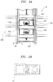
- Figure 2A is a front view of a lifting unit of the multistorey parking garage loaded with two automobiles on its liftable middle pan and its stationary lower pan, respectively;
- Figure 2B is a sectional view of a slide support for supporting the slidable movement of the lifting unit with respect to a rectangular pillar of a parking building;
- Figure 3 is a side view showing the two lifting units in a seesaw operation, while each loading two automobiles;
- Figure 4 is a perspective view showing a power transmission mechanism for operating the lifting unit;
- Figure 5 is a schematic front view showing an operation of a pair of roll guider units provided at opposite sides of an automobile holding pan of the lifting unit;
- Figure 6 is a view showing a centre rest for supporting a slender main drive shaft;
- Figure 7A is a bottom view of a conveyor belt drive mechanism provided on the bottom surface of the lower holding pan of each of the lifting units;
- Figure 7B is a schematic view showing a clutching operation of a clutch gear of the conveyor belt drive mechanism of Figure 7A;
- Figures 8A and 8B are plane views of a timing unit of the automated parking garage of the present invention, in which:
- Figure 8A shows a locked position of a timing sensor disc; and
- Figure 8B shows an unlocked position of the timing sensor disc;
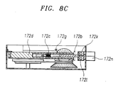
- Figure 8C is a sectional view of the timing unit taken along the section line A-A' of Figure 8B;
- Figures 9A and 9B are schematic views showing a middle pan lifting mechanism provided on a top plate of each of the lifting units, in which;
- Figure 9A shows the mechanism in running idle; and Figure 9B shows the mechanism in power transmitting state;
- Figures 10A and 10B are schematic views showing a second clutch of the main drive shaft, in which:
- Figure 10A shows a separated position of the clutch; and
- Figure 10B shows a clutching position of the clutch;
- Figures 11A and 11B are schematic views showing clutching operation of a third clutch of the conveyor belt drive mechanism of the present invention;
- Figure 12A is an enlarged perspective view of a belt segment of the conveyor belts of the present invention; Figure 12B is a plan view of the belt segment of Figure 12A;
- Figure 12C is a partial side view of an assembled conveyor belt for showing the side section of the belt segments hinged to each other;
- Figure 13A is a plan view of the conveyor belt having a plurality of belt segments;
- Figure 13B is a schematic side view showing the conveyor belt supported by a plurality of support rolls, preventing the deflection of the conveyer belt caused by its own weight;
- Figure 13C is a sectional view of the conveyor belt taken along the section line B-B' of Figure 13B;
- Figures 14A to 14C show front views of a ground stabilizer in accordance with the present invention, respectively, in which:
- Figure 14A shows the stabilizer at its holding position;
- Figure 14B shows the stabilizer at the initial stage of its release position; and
- Figure 14C shows the operation of the stabilizer.
-
Referring to the drawings, Figure 1 partially shows an automated multistorey parking garage in accordance with a preferred embodiment of the present invention, Figure 2A is a front view of a lifting unit of the multistorey parking garage loaded with two automobiles. Figure 2B is a sectional view of a slide support for supporting the slidable movement of the lifting unit, Figure 3 is a side view showing the two lifting units in a seesaw operation, and Figure 4 is a perspective view showing a power transmission mechanism for operating the lifting unit.
-
The parking garage includes a multistorey parking building, divided into two sections with a vertical elevator well or a shaft therebetween. A pair of automobile lifting units 100 and 100a are installed in the elevator well between the two sections such that they slidably seesaw in the elevator well, otherwise stated, one of the units 100 and 100a ascends while the other unit descends. The multistorey parking building is provided with a plurality of parking cells 300, each provided on every floor of each of divided building sections and having a pair of parking conveyor belts 104b. The parking conveyor belts cooperate with holding conveyor belts 104a, provided on the lifting units 100 and 100a, in every parking operation which will be described later herein. A drive power generating unit 1 is mounted on an uppermost part, or a penthouse, of the parking garage to generate a drive power for driving the lifting unit 100 and 100a as well as the holding and parking conveyor belts 104a and 104b. The output power or the rotational force of the drive unit 1 is transmitted to the lifting units 100 and 100a, so that one of the units is lifted while the other comes down. The output power is also transmitted to the conveyor belts of the lifting units 100 and 100a as well as the conveyor belts 104b of the parking cells 300. The power transmissions from the drive unit 1 to both the lifting units 100 and 100a and the conveyor belts 104a and 104b are carried out by individual power transmission mechanisms, which will be described in detail later herein. The aforementioned units 1, 100, 100a and the conveyor belts 104a and 104b operate under the control of a conventional control unit (not shown).
-
The pair of lifting units 100 and 100a have the same construction and thus one of the lifting units, for example, the lifting unit 100 will be referred to in the following description.
-
The lifting unit 100 has such two-storied structure that it has middle and lower automobile holding pans 102 and 104 as best seen in Figures 2 and 4. Here, the middle pan 102 is a liftable pan, while the lower pan is a stationary pan. A slender main drive shaft 201, connected to the drive unit 1 through a transmission gear 202, is vertically arranged and penetrates a corner of the lifting unit 100. This lifting unit 100 also has a top plate 101, having thereon a middle pan lifting mechanism 103. The mechanism 103 is in turn connected to the main drive shaft 201 using a chain gearing or a belt gearing, which will be described later herein. The liftable middle pan 102 together with the stationary lower pan 104 of the lifting unit 100 is provided with the pair of automobile holding conveyor belts 14a. The conveyor belts 104a cooperate with the parking conveyor belts 104b, provided on the parking cells 300, in parking operation. The stationary lower pan 104 is provided at its bottom surface with a conveyor belt drive mechanism 150. The mechanism 150 transmits the rotational force of the drive unit 1 to the conveyor belts 104a and 104b and controls their automobile conveying direction. As best seen in Figures 9A and 9B, the middle pan lifting mechanism 103 provided on the top plate 101 of the lifting unit 100 includes a bobbin shaft 108. The bobbin shaft 108 is adapted to tighten or loosen a wire or a chain 107 and is supported by a pair of end supports 109 and 109a fixed to the top plate 101. The bobbin shaft 108 is divided into two winding parts, about which individual wires are wound. The bobbin shaft 108 also includes a first spur gear 110 at its end. The first spur gear 110 selectively gears with a second spur gear 110a of a first clutch 112 which is operated under the control of first and second solenoids 111a and 111b. When the first and second spur gears 110 and 110a engage with each other, the rotational force of the main drive shaft 201 is transmitted to the bobbin shaft 108, so that the bobbin shaft 108 rotates in either direction and the liftable middle pan 102 of the lifting unit 100 is slidably moves upwards or downwards.
-
The first clutch 112 is provided with a bevel gear at its left end. This bevel gear 112b is driven by the rotational force of the main drive shaft 201. The rotational farce is transmitted to the bevel gear 112b through first to third transmission gears 208, 209 and 210 which are connected to each other by two endless chains or belts 113a and 113b. The first transmission gear 208 is integrally formed with the drive shaft 201 to rotate along with the shaft 201, while the third transmission gear 210 selectively engages with the bevel gear 112b of the first clutch 112. On the other hand, the second transmission gear 209 is used as a middle gear for transmitting the rotational force of the shaft 201 to the third transmission gear 210 through the two belts 113a and 113b. The first and second solenoids 111a and 111b operate under the control of the control unit (not shown) and controls the operation of the bobbin shaft 108. In order to control the bobbin shaft 108, a control rod 111a-1 of the first solenoid 111a, integrally formed with a movable core of the first solenoid 111a, selectively engages with the third spur gear 110b of the first clutch 112.
-
When the second solenoid 111b is applied with electric power, its movable core is retracted and makes the control rod 111b-1, locked to an annular locking groove 112a of the first clutch 112, move in the direction shown at the arrow A of Figure 9B. Such a movement of the control rod 111b-1 is attended with a movement of the first clutch 112 in the direction shown at the arrow B, so that the bevel gear 112b of the first clutch 112 engages with the third transmission gear 210. Hence, the rotational force of the main drive shaft 201 is transmitted to the bobbin shaft 108 through the first to third transmission gears 208, 209 and 210, the lever gear 112b, the second spur gear 110a and the first spur gears 110.
-
As shown in Figure 7, the conveyor belt drive mechanism 150, arranged on the bottom surface of the lower holding pan 104 of the lifting unit 100, includes a plurality of clutches as well as a plurality of solenoids, which will be described below. The drive mechanism 150 is provided with a second clutch 151, arranged on a corner of the lower holding pan 104 as shown in Figures 10A and 10B. The drive mechanism 150 further includes a third clutch 152 at the centre part spaced apart from the second clutch 151. As shown in Figures 10A and 10B, the second clutch 151 has a transmission gear 151a, while the third clutch 152 has a transmission gear 152a as shown in Figures 11A and 11B. The two transmission gears 151a and 152a are connected to each other by a chain or a belt 213b.
-
As shown in Figures 7A, 11A and 11B, the transmission gear 152a of the third clutch 152, connected to the main drive shaft 201 through the transmission gear 151a of the second clutch 151, engages with either of a pair of bevel gears 153 and 153a under the control of a fourth solenoid 154. The pair of bevel gears 153 and 153a are connected to individual transmission shafts 157 and 156. The fourth solenoid 154 is controlled by the control unit.
-
The transmission gear 152a of the third clutch 152 is arranged such that it moves leftwards or rightwards and engages with either the bevel gear 153a of the left-side transmission shaft 156 or the bevel gear 153 of the right-side transmission shaft 157 under the control of the fourth solenoid 154.
-
As shown in Figure 7A, the transmission shafts 156 and 157 are also provided with bevel gears 156b and 157b at their outer ends, respectively. In addition, a pair of clutch gears 158 and 158a are provided to achieve the selective power transmission between the bevel gears 157a and 156b and the transmission gears 311 and 311a, respectively. Here, the clutching operation of each of the clutch gears 158 and 158a is carried out by a linkage, comprising two link bars 160 and 160c, under the control of a fifth solenoid 159 or 159a. The two link bars 160 and 160c are linked to each other at an angle α ranged about 30° - 180° as shown in Figure 7B. When the clutch gears 158 and 158a displace in the directions shown at the arrows C and G of Figure 7A, the bevel gears 156b and 157b engage with or are separated from the transmission gears 311 and 311a and drive or stop the conveyor belts 104b of the right-side and left-side parking cells 300 of the parking building, respectively. Otherwise stated, the pair of fifth solenoids 159 and 159a, arranged at both sides of the bottom surface of the lower holding pan 104, are turned on or off under the control of a second switch 172n of a timer unit 170, which will be described in detail below. Hence, each of the control rods 159-1 and 159a-1 of the fifth solenoids 159 and 159a moves in the direction shown at the arrow D of Figure 7A. As a result, link operating bars or the control rods 159-1 and 159a-1, each connected to the linkage of the clutch gear 158 or 158a at an end thereof and to the fifth solenoid 159 or 159a at the other end thereof, move in the direction shown at the arrow E of Figure 7B, so that the clutching operation of the clutch gears 158 and 158a is achieved.
-
The timing unit 170, adapted to control the conveying distance of the conveyor belts 104a and 104b, is shown in detail in Figures 8A to 8C.
-
Here, Figure 8A shows the timing unit 170 when a timing sensor disc 172 is locked to a turning lever 172d and not rotated, Figure 8B shows the timing unit 170 when the timing sensor disc 172 is released from the turning lever 172d and rotated by the rotational force of the main drive shaft 201, and Figure 8C shows the timing unit 170 in the sectional view taken along the section line A-A' of Figure 8B.
-
The timing unit 170 includes a pair of bevel gears 176, engaging with each other and driven by the rotational force of the main drive shaft 201. In order to transmit the rotational force of the main drive shaft 201 to a drive gear of the bevel gears 176, a sprocket or a pulley 176a is provided. The pulley 176a is coaxially connected to the drive gear of the bevel gears 176 and indirectly connected to the main drive shaft 201 through a conventional transmission member, for example, a chain or a belt. The timing sensor disc 172 is connected to a pulley 172p of a driven gear of the bevel gears 176 through a conventional belt.
-
The turning lever 172d is hinged to a side wall of a casing of the timing unit 170 at an end thereof and includes therein a switch lever 172b, reciprocating in the direction shown at the arrow "m" of Figure 8B under the control of a sixth solenoid 171. The switch lever 172b is slidably arranged in a lever housing of the lever 172d and biased by a spring 172c outwards as best seen in Figure 8C.
-
The timing sensor disc 172 is a circular disc having a locking notch 172e at its periphery as well as a belt pulley at its outer periphery. This timing sensor disc 172 is rotatably mounted on the bottom surface of the casing of the timing unit 170.
-
The lever 172d further includes a protrusion 172g, which engages with a free end of a torsion spring 172h. The torsion spring 172h is mounted on a first switch 172j having a switch button 172j and adapted to control the seventh solenoid 213. The spring 172h is elastically supported between the first switch 172i and the protrusion 172g of the lever 172d such that it presses down the switch button 172j and turns on the first switch 172i when the lever 172d elastically turns clockwise under the control of the sixth solenoid 171 as shown in Figure 8B. Hence, the first switch 172i activates the seventh solenoid 213 and causes the rotational force of the main drive shaft 201 to be transmitted to the transmission gear 152a of the clutch 152. As best seen in the sectional view of Figure 8C, the timing unit 170 further includes a pair of operating rods 172k and 172l which are vertically arranged to penetrate the casing of the timing unit 170 and are spaced apart from each other by a predetermined distance. The operating rods 172k and 172l move in the direction shown at the arrow V of Figure 8A. These operating rods 172k and 172l have locking blocks 172m and 172m' at their middle portions, respectively. The locking blocks 172m and 172m' lock to a T-shaped free end of the switch lever 172b when the operating rods 172k and 172l descend as shown in Figure 8B. At this position, the locking blocks 172m and 172m' bias a torsion spring 172o of the second switch 172n, adapted for controlling all of the fifth solenoids 159 and 159a, downwardly. The torsion spring 172o thus presses down a switch button 172n' of the second switch 172n and turns on the fifth solenoids 159 and 159a. The operating rods 172k and 172l are connected to the control rod 159-1 of the fifth solenoid 159 through a link mechanism. Thus, the operating rods 172k and 172l cooperate with the fifth solenoid 159.
-
As depicted in Figures 4, 5 and 7A, each of the lifting units of the present invention is provided with a plurality of roll guider units 180 for covering the gap between the holding pan 104 of the lifting unit 100 and the parking pan of the parking cell 300. The roll guider units 180 are hinged to both sides of each of the middle and lower holding pans 102 and 104 and operated by control rods 159-1 and 159a-1 of the solenoids 159 and 159a. Each of the roll guider units 180, provided at each side of the holding pan 102 or 104, is connected to a pulley, cooperating with the control rods 159-1 or 159a-1, through a chain 181. Hence, the linear movements of the control rod 159-1 and 159a-1 of the fifth solenoids 159 and 159a result in the rotation of the pulleys, thereby tightening or loosening the chains 181 and erecting or spreading out the roll guider units 180. All of the roll guider units 180 should be erected when the lifting unit 100 ascends or descends with respect to the parking building, while they should be spread out to cover the gap between the holding pan of the lifting unit 100 and the parking pan of the parking cell 300 when the lifting unit 100 stops at a desired floor for parking the automobile. Each of the roll guider units 180 includes a plurality of rollers 182 which are rotatably mounted about a plurality of support bars 183. In addition, it is preferred to make the plurality of rollers 182 form a multi-stepped profile to improve the frictional force of the roll guider unit 180. In this case, the roll guider unit 180 causes the automobile to smoothly pass over with no jolt as well as no risk of an accident.
-
Each of the conveyor belts 104a and 104b, provided on the lifting units 100 and 100a as well as an the parking cells 300, comprises a plurality of belt segments 320. As shown in Figures 12A to 12C, each of the belt segments 320 comprises lower and upper plates 302 and 303, tightly combined with each other with a filler 309 interposed therebetween. The filler 309 is preferably made of a plastic material. The belt segment 320 further includes a plurality of protrusions 301 on the upper plate 303 such that the automobiles is stably held by and stably conveyed by the conveyor belts 104a and 104b in conveying operation.
-
Figures 13A to 13C show an assembled conveyor belt, for example, the holding conveyor belt 104a, in a plan view, in a side view and in a front sectional view, respectively. Each of the belt segments 320 of the conveyor belt 104a has a plurality of pin holes 305 at its opposite sides. The hinged combination of the plurality of belt segments 320 into the conveyor belt 104a is achieved by inserting a connection pin into the pin holes 305 of the belt segments 320. The belt segment 320 also includes a plurality of sprocket slots 306, engaging with sprockets 307 as shown in Figure 13B, at its both ends. Here, each of the sprockets 307 is rotated by the drive force transmitted from the conveyor belt drive mechanism 150 provided under the lower holding pan 104. In order to prevent deflection of the conveyor belt 104a due to its own weight, a plurality of support rolls 310 are provided under both sides of the conveyor belt 104a while being rotatable supported by a pair of brackets 310a as shown in Figure 13B. Such conveyor belts 104a and 104b are installed on the middle and lower holding pans 102 and 104 of the lifting units 100 and 100a as well as on the parking cells 300 of the parking building. The conveyor belts 104a of the lifting unit 100 cooperate with those of the parking cell 300 in a parking operation for the automobiles. It is preferred to make the length of each of the parking conveyor belts 104b be longer than a total width of two automobiles by 1.2 - 2.0 times.
-
The drive power generating unit 1 is provided at the penthouse of the parking garage as shown in Figure 1 and includes a drive motor or an internal combustion engine for generating the drive power or the rotational force. The drive power generating unit i includes a first drive force output part 2, connected to the pair of transmission pulleys or transmission gears 202 of the main drive shafts 201 to drive the gears 202. The drive unit 1 further includes a second drive force output part 3 connected to the second drive shaft 203 which controls the lifting operation of the lifting units 100 and 100a.
-
As depicted in Figure 1, the drive force of the drive unit 1 is transmitted to the lifting units 100 and 100a or the conveyor belts 104a and 104b through individual transmission mechanism. The main drive shafts 201 together with the second drive shaft 203 are directly connected to the drive unit 1. Here, the two main drive shafts 201 are vertically arranged from the ground floor to the penthouse of the parking garage such that they penetrate the lifting units 100 and 100a, respectively. The second drive shaft 203 is arranged on the penthouse of the parking garage such that it is parallel with the ground surface.
-
The second drive shaft 203 is provided at its centre part with a pair of sprockets 205 each of which is provided with a track about its outer periphery adapted to provide a positive engagement with a chain 206 which warps about and hangs from the sprocket 205 to the upper plate 101 of each of the lifting units 100 and 100a.
-
Each of the main drive shafts 201 has a key slot 207 throughout its length as shown in Figure 4 and transmits the rotational force of the drive unit 1 to the middle pan lifting mechanism 103 through the first to third transmission gears 208, 209 and 210. The main drive shaft 201 also transmits the rotational force of the drive unit 1 to the conveyor belt drive mechanism 150, provided on the bottom surface of the lower holding pan 104, through the fourth and fifth transmission gears 211 and 212. The rotational force transmitted to the conveyor belt drive mechanism 150 is in turn transmitted to the timing unit 170, the roll guider units 180 and the conveyor belts 104a and 104b through the aforementioned clutches, thereby achieving the parking operation.
-
Turning to Figures 14A to 14C, there is shown a ground stabilizer 350 provided at the bottom of the elevator well of the parking building to cushion the mechanical shock generated when the lifting units land on the bottom of the elevator well. This stabilizer 350 also levels the lower holding pan 104 of the lifting unit with the ramp of the building.
-
The stabilizer 350 includes a top plate 351 which is disposed on the bottom of the elevator well such that it is normally levelled with the ramp. This top plate 351 is provided at its lower surface with both a stopping assembly 360 for elastically holding the top plate 351 at a predetermined position and means 352 for upwardly biasing the top plate 351.
-
In the embodiment of Figures 14A to 14C, a compression coil spring 353 is used as the biasing means 152, however, it should be understood that the biasing means 352 may be selected from a conventional hydraulic device and a conventional pneumatic device other than the coil spring 353 without affecting the functioning of this invention. When the lifting unit lands on the top plate 351, a plurality of stopping probes 361 of the stopping assembly 360 escape from individual slots 362 provided on the side walls of the well, thereby making the top plate 351 be freed from the locked position. At this free state, the top plate 351 elastically moves upwards or downwards by the restoring force of the compression coil spring 353 or by the weight of the lifting unit.
-
The stopping assembly 360 further includes the same number of pressure probes 359 as that of the stopping probes 361. The pressure probes 359 penetrate individual through holes provided at the top plate 351 to protrude upwards from the upper surface of the top plate 351. The stopping probes 361 are elastically received in individual horizontal housings, which are mounted on the lower surface of the top plate 351. These stopping probes 361 normally protrude out of the sides of the top plate 351 to be inserted into the slots 362 of the side walls. The stopping assembly 360 further includes a L-shaped lever 355 which is hinged at its centre to a support column 357 by a pin 356. The column 357 downwardly extends from the lower surface of the top plate 351. Opposite sharpened ends 355a and 355b of the L-shaped lever 355 come into contact with a stopper 354 of the pressure probe 359 and a stopper 353a of the stopping probe 362, respectively, such that the lever 355 turns about the pin 357 as a result of the movement of the stoppers 359 and 361.
-
At the rear end of the stopping probe 361, it is biased by a tension coil spring 358 such that it is always biased outwards. The tension coil spring 358 is connected to both the rear end of the probe 361 and the probe housing at its opposite ends, respectively. Thus, when the lifting unit lands on the top plate 351 and imparts its weight to the top plate 351, the pressure probe 359 of which the upper end protrudes beyond the top plate 351 retracts and this causes the stopper 354 of the pressure probe 359 to move downwards. The downward movement of the stopper 354 causes the counterclockwise rotation of the L-shaped lever 355 about the pin 356, thus causing the stopper 353a of the stopping probe 361 to move leftwards along with the stopping probe 361 while overcoming the spring force of the tension coil spring 358. As a result, the stopping probe 361 escapes from the slot 362 and makes the top plate 351 be free.
-
Hereinbelow, the operational effect of the parking garage of the present invention will be described.
-
When the lifting unit 100 is positioned on the ground stabilizer 350, an automobile CA1, positioned on the ramp of the ground floor GND of the parking garage as shown in Figure 1, is conveyed to the second automobile holding chamber 102a on the liftable middle holding pan 102 of the lifting unit 100 under the control of an automatic or manual sensing unit. Thereafter, the first automobile holding chamber on the stationary lower holding pan 104 is opened by lifting the middle holding pan 102 loaded with the automobile CA1, and in turn loaded with another automobile CA2.
-
If described in detail, the automobile CA1 is loaded on the liftable middle holding pan 102 which is lowered to level with the ground floor GND of the parking building. When it is accomplished the loading operation for the automobile CA1, the control unit controls the drive unit 1 to rotate only the main drive shaft 201 and to lift the liftable middle pan 102 to a predetermined position. Hence, the drive force of the drive unit 1 is transmitted to the first transmission gear 208 through the main drive shaft 201. At this time, in order to activate the second clutch 151 of the drive mechanism 150, having been in the idle position as shown in Figure 10A, the control unit turns on the fifth to seventh solenoids 159, 159a, 171 and 213. The movable core of the seventh solenoid 213 is thus activated and advances the control rod 213a of the solenoid 213. Thus, the link 213b connected to the control rod 213a ascends and achieves the clutching position of the second clutch 151 as shown in Figure 10B, thereby achieving the power transmission through the second clutch 151. The drive force is in turn transmitted to the second and third transmission gears 209 and 210 through the chains 113a and 113b in order.
-
The transmitted drive force is in turn controlled by the first and second solenoids 111a and 111b in its transmission. Otherwise stated, the first clutch 112 prevents the drive force or the rotational force of the main drive shaft 201, transmitted to the third transmission gear 210, from being further transmitted as shown in Figure 9A. At this state, the second solenoid 111b is turned on by the control unit so as to open the first holding chamber under the movable middle pan 102 of the lifting unit 100 and to load the automobile CA2 on the first holding chamber. Upon turning on the second solenoid 111b, the movable core of the solenoid 111b is activated and makes the control rod 111b-1 of the solenoid 111b move in the direction shown at the arrow A of Figure 9B. Hence, the bevel gear 112b, connected to the control rod 111b-1 at the locking groove 112a of the clutch 112, advances to engage with the rotating third transmission gear 210. At the same time of turning on the second solenoid 111b, the first solenoid 111a is turned on and retracts its control rod 111a-1 thereby releasing the third spur gear 110b from the control rod 111a-1 as shown in Figure 9B. Thus, the rotational force of the third transmission gear 210 is transmitted to the first spur gear 110 and in turn transmitted to the bobbin shaft 108, so that the bobbin shaft 108 is rotated to wind the wire 107. As a result of the winding of the wire 107, the liftable middle pan 102 of the lifting unit 100 ascends in the direction shown at the arrow F of Figure 4 to open the first automobile holding chamber. Here, the ascending distance of the liftable middle pan 102 is controlled by the control unit cooperating with a conventional limit switch (not shown). When the control unit is applied with an input signal, outputted from the limit switch and indicating that the liftable middle pan 102 reaches a predetermined height, it turns off the first and second solenoids 111a and 111b. Thus, the first clutch 112 returns to its running idle state as shown in Figure 9A. The aforementioned operation for opening the first holding chamber is followed by an additional loading operation, adapted for loading another automobile CA2 on the opened first holding chamber and performed by the conveyor belt drive mechanism 150 as well as the timing unit 170.
-
As shown at the solid line of Figures 7A and 7B, the clutch gears 158 and 158a do not engage with the seventh transmission gears 311 and 311a but engage with the sixth transmission gear's 161 and 161a, thereby running idle along with the transmission gears 161 and 161a, respectively. At this state, one of the fifth solenoids 159 and 159a is turned on by the control unit so as to move downwards the control rod 159-1 or 159a-1, connected to the movable core of the solenoid 159 or 159a, thereby straightening the corresponding link 160 or 160a as shown at the dotted line of Figure 7B. Therefore, one of the clutch gears, for example, the clutch gear 158 engages with the sixth transmission gear 161 as well as the seventh transmission gear 311, so that the drive force is transmitted to the seventh transmission gear 311 through the power transmission mechanism in order of the fifth transmission gear 212, the bevel gear 153, the driven shaft 157, the bevel gear 157a, the sixth transmission gear 161 and the clutch gear 158. The drive force transmitted to the seventh transmission gear 311 is in turn transmitted to the conveyor belt drive sprocket 307, connected to the shaft of the seventh transmission gear 311, thereby rotating the sprocket 307. Thus, the automobile CA2 is automatically conveyed in the direction shown at either of the arrows G and H of Figure 1.
-
The timing unit 170 is operated at the same time of operation of the fifth solenoids 159 and 159a. As shown in Figures 8A to 8C, the control rod 171a of the sixth solenoid 171 which is turned on at the same time of operation of the fifth solenoids 159 and 159a, thereby causing the lever 172d to turn clockwise.
-
Thus, the locking member 172q of the lever 172d is released from the locking notch 172e of the timing sensor disc 172 as depicted in Figure 8B, so that the timing sensor disc 172 is rotated clockwise by the rotational force of the main drive shaft 201 transmitted through the bevel gears 176. In addition, the clockwise turning of the lever 172d causes the switch lever 172b to be inserted into the hollow part of the lever 172d in the direction shown at the arrow m at the same time of biasing the torsion spring 172h downwards. Upon being biased downwards, the torsion spring 172h presses down the switch button 172j of the first switch 172i, so that the turning-on state of the seventh solenoid 213 is continued. In design of the timing unit 170, the timing sensor disc 172 is designed such that one revolution thereof causes each of the conveyor belts 104a and 104b to move in a distance corresponding to a width of an automobile to be parked. Thus, one revolution of the timing sensor disc 172 achieves the automatic conveyance of the automobile by the distance corresponding to the width of the automobile.
-
When the locking notch 172e is returned to its locking position after one revolution of the timing sensor disc 172, the lever 172d is automatically turned counterclockwise by the restoring force of a compression coil spring 172f. Thus, the locking member 172q of the lever 172d is locked to the locking notch 172e. At the same time, the counterclockwise turning lever 172d pushes the locking block 172m or 172m' of the operating rod 172k or 172l upwards. Hence, the torsion spring 172o of the second switch 172n is released from its biased position, so that the pressed switch button 172n' is released as depicted in Figure 8A. The fifth solenoid 159 or 159a, connected to the second switch 172n, is thus turned off, so that the clutch gear 158 returns to its running idle position as shown at the solid line of Figure 7B, thereby stopping the conveyor be to. At the same time, each nf the roller guider units 180, cooperating with the corresponding fifth solenoid 159 or 159a, returns to its erected position as shown at the solid line of Figure 5.
-
Therefore, the loading operation for the automobile CA2 onto the first holding chamber of the lifting unit 100 is achieved as shown in Figure 2A.
-
Hereinafter, it will be described the parking operation for the automobiles CA1 and CA2 from the lifting unit 100 to the parking cells 300 of the parking building.
-
Upon accomplishing the loading operations for the automobiles CA1 and CA2 on the lifting unit 100 as shown in Figure 2A, the second drive shaft 203 other than the main drive shafts 201 is rotated by the drive force of the drive unit 1 under the control of the control unit. The second drive shaft 203 is provided at its centre portion with the sprocket 205 having the track about its outer periphery adapted to provide the positive engagement with the chain 206 which hangs from the sprocket 205 to the upper plate 101 of the lifting unit 100 through a support roller 214 as shown in Figure 4. Hence, the rotation of the second drive shaft 203 causes the seesaw operation of the lifting units 100 and 100a in the direction shown at the arrows I and I of Figure 3. As a result, one of the lifting units 100 and 100a ascends while the other lifting unit descends.
-
When a lifting unit, for example, the lifting unit 100, reaches a desired floor of the parking building as a result of the aforementioned seesaw operation of the lifting units 100 and 100a, the limit switch provided at the parking building outputs a signal, indicative of reaching of the lifting unit 100, to the control unit. Upon reception of the signal, the control unit stops the seesaw operation of the lifting unit 100 and 100a by controlling the drive unit 1.
-
When the lifting unit 100 reaches the desired floor as described above, the parking operation for the automobiles CA1 and CA2 is performed under the control of the control unit. In order to park the automobiles on the parking cells, the power transmission mechanism operates the conveyor belts 104a and 104b in a direction opposite to that of the aforementioned loading operation, so that the automobiles CA1 and CA2 are orderly conveyed and parked as follows.
-
When the lifting unit 100 loaded with the automobiles CA1 and CA2 reaches the desired floor of the parking building, the fifth solenoid 159a is activated to retract its control rod 159a-1 in the direction shown at the arrow E of Figure 7B, thereby straightening the linkage 160 and 160c as shown at the dotted line of Figure 7B. Therefore, the clutch gear 158a engages with the sixth transmission gear 161a as well as the seventh transmission gear 311a. Here, the gear 311a is directly connected to the conveyor belt driving sprocket 307 as described above. The drive force is thus transmitted to the seventh transmission gear 311a through the transmission mechanism in order of the fifth transmission gear 212, the bevel gear 153a, the transmission shaft 156, the bevel gear 156b, the sixth transmission gear 161a and the clutch gear 32 158a. The drive force is in turn transmitted to the conveyor belt driving sprocket 307 and drives the conveyor belts 104b at the same time of driving the conveyor belts 104a of the lifting unit 100.
-
At the same time of the aforementioned power transmission, the sixth solenoid 171 is activated to operate its control rod 171a, thereby operating the timing unit 170 as described in the aforementioned automobile loading operation.
-
That is, when the conveyor belts 104a and 104b move by a distance corresponding ta the width of the automobile to be parked, the timing sensor disc 172 is rotated and separates the clutch gear 158a from the seventh transmission gear 311a, thereby causing the clutch gear 158a to run idle, and stopping the conveyor belts.
-
The parking operation for the automobile CA2 loaded on the lower automobile holding pan 104 is followed by the parking operation for the other automobile CA1 loaded on the liftable middle holding pan 102. In order to park the automobile CA1, the liftable holding pan 102 is lowered by the middle pan lifting mechanism 150 until it is levelled with the parking pan of the parking building. Thereafter, the parking operation for the automobile CA1 is carried out in the same manner as described in the aforementioned parking operation for the automobile CA2.
-
In the present invention, each of the lifting units 100 and 100a is slidably mounted on the support columns 50 of the parking building. In addition, each of the slender main drive shafts 201 is supported by a centre rest 250 or 250a at its middle portion as shown in Figure 6, thereby preventing from damage due to the vibration.
-
In the present invention, the lower holding pan 104 of the lifting unit 100 is levelled with the ramp of the ground floor of the parking building thanking for the ground stabilizer 350 shown in Figures 14A to 14C.
-
Otherwise stated, when the lifting unit 100 lands on the top plate 351 of the stabilizer 350 and imparts its weight to the top plate 351, the pressure probe 359 of which the upper end protrudes beyond the top plate 351 retracts and this causes the stopper 354 of the pressure probe 359 to move downwards as shown in Figure 14B. Here, since the lower section of the stopper 354 comes into contact with the end 355a of the L-shaped lever 355, the downward movement of the stopper 354 causes the counterclockwise rotation of the L-shaped lever 355 about the pin 356. At this time, the other end 355a of the lever 355 comes into contact with the stopper 353a of the stopping probe 361, the counterclockwise rotation of the L-shaped lever 355 causes the stopper 353a of the stopping probe 361 to move leftwards along with the stopping probe 361 while overcoming the spring force of the tension coil spring 358. As a result, the stopping probe 364 escapes from the slot 362 and makes the top plate 351 be free. The top plate 351 thus elastically lowers as shown at the phantom line of Figure 14C while overcoming the spring force of the compression coil spring 353, so that the lower holding pan 104 of the lifting unit 100 is levelled with the ramp of the ground floor of the parking building and causes no trouble in loading the automobile on the holding pan 104.
-
As described above, the present invention provides an automated multistorey parking garage in which two elevators cooperate with each other in such a manner that one of them ascends while the other descends. Each of the lifting units has a two-storied construction in that it has a liftable middle pan and a stationary lower pan which are adapted to be loaded with individual automobiles. The middle pan can move upwards and downwards with respect to the stationary lower pan to an extent that it is levelled with ground floor, thereby loading thereon an automobile. In the lifting unit of the present invention, upon loaded with the automobile, the liftable middle pan ascends to provide a space for loading another automobile on the stationary lower pan. Thanking for such a two-storied construction of each of the lifting units, the parking garage provides an improved parking capacity of eight automobiles for every floor of the parking building.
-
In addition, the parking garage of the present invention is provided with conveyor belts on the lifting units as well as on the parking cells of the parking building, thereby automatically conveying the automobiles to be parked. The conveyor belts are automatically controlled in their moving direction such that they convey the automobile leftwards or rightwards. The conveyor belts is also controlled in their moving distance by a timing unit such that they moves by a predetermined distance, corresponding to a width of the automobile to be parked, at a time. Such an automatic control for the conveyor belt moving distance improves, in cooperation with title aforementioned improved parking capacity, the space efficiency of the parking garage.
-
Furthermore, each of the belt segments of the conveyor belts is provided with a plurality of non-slip protrusions and, as a result, efficiently prevents the automobile from being slipped on the conveyor belts. Each of the lifting units has a roll guider unit for selectively covering a gap between the holding pan of the lifting unit and the parking pan of the parking cell, thereby permitting the automobile to pass over the gap without jolting.
-
Although the preferred embodiments of the present invention have been disclosed for illustrative purposes, those skilled in the art will appreciate that various modifications, additions and substitutions are possible, without departing from the scope of the invention as disclosed in the accompanying claims.