EP0620319B1 - Control device for asphalt finisher - Google Patents
Control device for asphalt finisher Download PDFInfo
- Publication number
- EP0620319B1 EP0620319B1 EP19940105519 EP94105519A EP0620319B1 EP 0620319 B1 EP0620319 B1 EP 0620319B1 EP 19940105519 EP19940105519 EP 19940105519 EP 94105519 A EP94105519 A EP 94105519A EP 0620319 B1 EP0620319 B1 EP 0620319B1
- Authority
- EP
- European Patent Office
- Prior art keywords
- screed
- detection devices
- vehicle member
- reference line
- line
- Prior art date
- Legal status (The legal status is an assumption and is not a legal conclusion. Google has not performed a legal analysis and makes no representation as to the accuracy of the status listed.)
- Expired - Lifetime
Links
- 239000010426 asphalt Substances 0.000 title claims description 27
- 238000001514 detection method Methods 0.000 claims description 64
- 230000007423 decrease Effects 0.000 claims description 2
- 230000001678 irradiating effect Effects 0.000 claims description 2
- 239000004065 semiconductor Substances 0.000 claims description 2
- 238000006073 displacement reaction Methods 0.000 description 11
- 238000010276 construction Methods 0.000 description 4
- 238000000034 method Methods 0.000 description 3
- 239000000203 mixture Substances 0.000 description 3
- 238000012545 processing Methods 0.000 description 3
- 238000007688 edging Methods 0.000 description 2
- 238000012544 monitoring process Methods 0.000 description 2
- 238000013459 approach Methods 0.000 description 1
- 239000012141 concentrate Substances 0.000 description 1
- 238000012790 confirmation Methods 0.000 description 1
- 238000012937 correction Methods 0.000 description 1
- 238000013461 design Methods 0.000 description 1
- 238000010586 diagram Methods 0.000 description 1
- 239000012530 fluid Substances 0.000 description 1
- 230000000977 initiatory effect Effects 0.000 description 1
- 230000000007 visual effect Effects 0.000 description 1
Images


Classifications
-
- E—FIXED CONSTRUCTIONS
- E01—CONSTRUCTION OF ROADS, RAILWAYS, OR BRIDGES
- E01C—CONSTRUCTION OF, OR SURFACES FOR, ROADS, SPORTS GROUNDS, OR THE LIKE; MACHINES OR AUXILIARY TOOLS FOR CONSTRUCTION OR REPAIR
- E01C19/00—Machines, tools or auxiliary devices for preparing or distributing paving materials, for working the placed materials, or for forming, consolidating, or finishing the paving
- E01C19/004—Devices for guiding or controlling the machines along a predetermined path
- E01C19/006—Devices for guiding or controlling the machines along a predetermined path by laser or ultrasound
-
- E—FIXED CONSTRUCTIONS
- E01—CONSTRUCTION OF ROADS, RAILWAYS, OR BRIDGES
- E01C—CONSTRUCTION OF, OR SURFACES FOR, ROADS, SPORTS GROUNDS, OR THE LIKE; MACHINES OR AUXILIARY TOOLS FOR CONSTRUCTION OR REPAIR
- E01C2301/00—Machine characteristics, parts or accessories not otherwise provided for
- E01C2301/14—Extendable screeds
- E01C2301/16—Laterally slidable screeds
Definitions
- the invention relates to a device as contained in the preamble of claim 1.
- a device of this type is know from the JP. Utility Model H3-34781.
- the automatic directional control device (H4-32883) was designed to detect the travel direction of an asphalt finisher (referred to as the finisher herein below) in accordance with the signals emitted from three light sensors which are arranged laterally on the front section of a finisher body to detect a reference line disposed on a roadside.
- the screed is a device for levelling the asphalt within a defined region of the road so as to align appropriately to the edges of the road, and is disposed on the side sections of the finisher.
- the screeds are required to be extended or retracted depending on the position of the finisher with respect to the reference line. In a conventional finisher, this operation is performed manually by a finisher operator who controls fluid pressure in a plurality of hydraulic cylinders so as to move the cylinders to left or right in accordance with his visual confirmation of the reference line and instructions from a screed manager.
- the screed manager is responsible for the quality of the paved road, and he may be required to travel from side to side to check the direction of the travel or he may choose to assign the task of monitoring the road width to a couple of sidemen to watch the edges of the laid down asphalt, so that he may concentrate on the duty of maintaining the paving quality.
- Such working conditions are generally not satisfactory and ultimately resulted in manual adjustments of the road width, and other such labor-intensive corrective measures.
- H3-34781 An improvement in the conventional approach was achieved in the above-noted invention (H3-34781), by providing a detector, such as a CCD camera to detect the reference line, so as to control the extension or retraction of the screed by a screed controller.
- a detector such as a CCD camera
- This screed controller described above presented the following problem, however.
- the detector is disposed at the rear section of the finisher, and if the road width is becoming narrow, the front edge of the screed projects outward of the road and results in laying down of the asphalt mixture beyond the reference line.
- This type of design is also not applicable when the reference line is based on roadside objects which project out of the ground surface, because the screed tended to collide with it.
- the purpose of the present invention is to present a simple and cost effective control system for controlling the paving operation with the use of an asphalt finisher having a plurality of screeds for levelling the asphalt, in conjunction with an automatic control of steering for the asphalt finisher.
- a screed can be provided with the above described screed controller comprising a forward and a rearward detection devices on the side of the screed, and determines whether the road is becoming wider, narrower or remain at a constant width in terms of forward and rearward detection devices. Therefore, in all the cases of road width conditions, the screed controller of the present invention is able to prevent the end section of the screed to extend beyond the reference line.
- the screed controller of the above configuration is incorporated in an automatic control system including a device for steering the asphalt finisher of the present invention, so as to perform an efficient paving operation using a relatively inexpensive control system.
- the automatic control device comprises: a steering device for controlling the direction of travel of the asphalt finisher having a plurality of screeds for performing a levelling operation; a screed controller for controlling the extension or retraction of the plurality of screeds to the left or to the right of the asphalt finisher; a detection device disposed on a side region of a screed for determining the position of a reference line generated in relation to a roadside line; a master controller for controlling the operation of the screed controller and a steering device for directing the movement of the asphalt finisher in accordance with the output data from the detection device.
- the screed can be provided with the above described screed controller comprising a forward and a rearward detection device on the side of the screed for generating an image of the reference line along the roadside, and the resulting image is utilized as a control guide for determining the amount of deviation of the asphalt finisher with respect to the reference line.
- the detection devices are interconnected electrically with the screed controller to provide automatic extension or retraction adjustments in the position of the screed with respect to the reference line.
- the automatic control device of the present invention for steering the direction of the asphalt finisher operates in conjunction with the screed controller as described above to provide an efficient and cost effective paving operation.
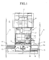
- Figure 1 is a schematic plan view showing an arrangement of the key members of an asphalt finisher.
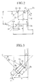
- Figure 2 shows the relationship between the steering angle and the deflection angle of the vehicle member.
- Figure 3 shows the relationship between the steering angle and the deviation angle.
- FIG. 4 is an illustration to explain the steering correction operation.
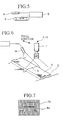
- Figure 5 is a schematic illustration of the relationship between the screed and the screed controller.
- Figure 6 is an example of the arrangement of the control device of the present invention.
- Figure 7 is an example of the display of the image generated.
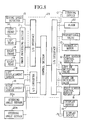
- Figure 8 is a block diagram to show the inter-relationship of the control devices and the detection devices.
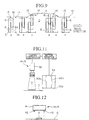
- Figure 9 is a schematic illustration to explain the control operation for extension or retraction of the screed.
- Figure 10 is a flow chart for the directional control operation.
- Figure 11 is a schematic drawing showing the arrangement for another detection device.
- Figure 12 is a schematic drawing showing the arrangement for yet another detection device.
- the reference numeral 1 refers to an asphalt finisher (hereinbelow shortened as finisher).
- the finisher 1 is provided with a vehicle member 2 which has a hopper 3 at its front section, and it is provided with a screw member 5 at its rear section, which serves to spread the asphalt mixture, forwarded from the hopper 3 by a feeder 4, to the left and right directions of the finisher 1.
- the finisher 1 is also provided with a left-right pair of screeds 6 for levelling the asphalt mixture spread by the screw member 5.
- the vehicle member 2 is provided with a pair of front wheels 2a (refer to Figure 2) and a pair of rear wheels 2b, and changes its travel direction by having the front wheels 2a rotated to left or right about a king pins 2c by means of the steering device 10 (refer to Figure 8).
- An operator sits in a driver seat 7 provided in the vehicle member 2 to take command of the finisher operation.
- the pair of screed 6 is disposed with one screed in a slightly leading position ahead of the other, and can be controlled independently of the other by a screed controller 8 to extend the screed 6 to left or right.
- a screed controller 8 There is an electromagnetic switching valve (referred to as EM-switching valve) 9, shown in Figure 8, in each of the hydraulic control circuit of the screed controller 8 for changing the direction, of motion of the screed controller 8.
- EM-switching valve electromagnetic switching valve
- Each of the screed 6 is provided with an end plate 6a.
- the vehicle member 2 is driven by a hydraulic motor 12 whose speed is varied by a proportional valve 11 (refer to Figure 8), and the speed is monitored by a moving speed detector 13.
- a proportional valve 11 (refer to Figure 8)
- each of the end plates 6a On the side surface of each of the end plates 6a are disposed a forward detection device 14 disposed separately from a rearward detection device 15 along a line parallel to the longitudinal center line of the vehicle member 2.
- the detection devices 14, 15 are composed of a semiconductor laser emitter 16 (refer to Figure 6) and a CCD camera 17, respectively.
- the laser emitter 16 emits a slit-shaped laser beam which irradiates a reference line (plane) A, consisting of fixed objects along the roadside of the paving road, such as edging stones, and the camera 17 records an illuminated line B generated by irradiating the fixed objects along the reference line A, and displays the image B on the screen of a display device 17a (refer to Figure 7).
- FIG 7 An example is shown in Figure 7, which shows a case of the screed 6 being in the correct position with respect to the reference line A, and in this case, the image B is symmetrical about a vertical line, and is disposed in the horizontal center of the screen
- the travel direction of the finisher can be altered by monitoring the steering angle ⁇ and ⁇ (refer to Figure 2) from the vehicle member 2 in accordance with the output signals from a pair of steering angle sensors 20a,20b shown in Figure 8, which monitor the rotation angles of the pair of front wheels 2a which rotate about the king pins 2c.
- the detection devices 14, 15 are electrically connected to an image processing section 21.
- the image processing section 21, the moving speed detector 13, the displacement sensors 18, the EM-switching valves 9, the proportional valves 11, the display devices 17a, 19, the steering device 10, the steering angle sensors 20a, 20b and an alarm device 22 are all connected electrically to the master controller 23.
- the master controller 23 comprising various microcomputers performs the following functions.
- the deflection i is determined in accordance with the Ackermann-Jantaud rotation theory which states that when a vehicle 2 makes a turn, the vehicle 2 turns about a point of intersection O of the line of extension of the axial center line of the front wheel 2a with the line of extension of the axis of the rear wheel 2b.
- a control mode can be a left side mode in which the reference line A is on the left, or a right side mode in which the reference line A is on the right of the vehicle member 2; as well as a center mode, in which the amount of extension or retraction of the screed 6 is the same on the right and the left.
- Figure 9 shows a basic example of automatic control of the displacement of only the screed 6.
- the case shown in position (a) is one of no change in the road width of the road D.
- the display screen on the controller 23 shows an output image from the forward and rearward detection devices 14, 15 which is the same as that shown in Figure 7. From this image, the controller 23 judges the road dimension to be unchanging, and selects the rearward detection device 15 to perform the trancer control. In this case, since the road width is not changing, the screed 6 do not need to be moved, and the existing positions of the screed 6 is maintained.
- the forward detection device 14 detects that the reference line A has moved outward, but since the control is being undertaken by the selected rearward detection device 15, the screed does not change positions, and proceed as they are.
- the rearward detection device 15 reaches the initial point of widening of the road, this detection device 15 too detects that the reference line A is outside its boundary.
- the controller 23 generates a command signal to the EM-switching val-ve 9 to operate the screed controller 8 so as to follow the reference line A as depicted in position (c).
- the control methodology is essentially the same as in position (a).
- the forward detection device 14 detects that the reference line A has moved inward, and the controller understands that the road width is becoming narrow, and this time, selects the forward detection device 14.
- the result is that the control action over the trancer control is now switched from the rearward detection device 15 to the forward detection device 14.
- the controller 23 now issues a command signal to the EM-switching valve 9 to operate the screed 6 to operate the screed controller 8 in the opposite direction to the previous case. This is depicted in the position (e) in which the screed 6 is now in a retracted position.
- the controller 23 again selects the rearward detection device 15 and the control methodology becomes the same as in position (a) . This is depicted in position (f).
- the controller 23 may activate the alarm device 22.
- the operator is able to assess the paving conditions from the displays in the display devices 17a, 19 and from such warning signal sounded by the alarm device 22.
- Figures 2 to 4 illustrate some examples of the steering control. Severe and rapid directional change is not desirable from the standpoint of making safe paving as well as from the safety of the paving operation. Therefore, the amount of steering is limited to the following three conditions.
- the control device can be placed in automatic mode, and in this case, the operator selects the control mode (left side mode, right side mode or center mode).
- the screed controller 8 is operated on the reference line A to set a reference value, and the value of the stoke of the cylinder of the screed 6 is inputted into the controller 23.
- the point of intersection O is defined by replacing the distance to the reference line A with the value of the stroke.
- the operator also selects the automatic mode from the choices between automatic control or manual control operational mode.
- the detection mode is set to be two detection devices 14, 15 (a total of four including the left and right side devices).
- step S1 it determines whether the finisher 1 is moving or not moving. If the finisher 1 is moving, the decision is yes, and it proceeds to step S2. In step S2, it determines whether the finisher 1 is in automatic or manual mode. If the finisher 1 is in automatic mode (Yes), then it proceeds to step S3, and it examines if there are two devices for the detection device 14, 15. If yes, it proceeds to step S4, and it examines whether the deviation angle ⁇ is less than the allowable value. If the deviation angle ⁇ is more than the allowable value (referred by No), it proceeds to step S5.
- step S5 it computes the steering angles ⁇ , ⁇ for the front wheels 2a, and inputs the value in the steering device 10 in step S6.
- step S7 it operates the steering device 10 until the longitudinal center line of the vehicle member 2 (or the line joining the detection devices 14, 15) becomes parallel with the reference line A.
- step S9 it proceeds to step S9.
- step S4 if the result is Yes, it proceeds to step S8, and it examines whether the displacement value ⁇ m is less than the allowable value, and if the result is No, it proceeds to step S9.
- step S9 it computes the steering angle to make the line joining the detection devices 14, 15 and the reference line A parallel, and outputs this value to the screed controller 8 in step S10, and it proceeds to step S11.
- step S11 it operates the screed controller 8 until the computed value is attained, and when the result becomes Yes, then the steering angle becomes zero, and the operation is completed.
- the edge line of the leading finisher 1 is usually used as the reference line A by the trailing finisher 1.
- the inner rearward detection device 15 of the trailing finisher 1 cannot function because of the loss of the reference line A which has been eliminated by the paving made by the trailing finisher 1.
- the trailing finisher 1 is then left only with the forward detection device 14.
- the detection mode is set to be the detection mode using only the one detection device 14. This mode in step S3 results in No, and it leads to another separate mode of operation (forward sensor steering).
- FIG 11 shows another embodiment of the system of detection devices 14, 15 of the present invention.
- this system there is provided a series of (latent) check points 30b on the screen of the display device 30a.
- the positions of the check points 30b can be specified at will anywhere on the screen.
- the system is designed to alert the operator by generating a signal when the reference line A coincides with one of the check points 30b. After selecting the position for the check points 30b on the screen, there is no need to keep displaying the check points 30b on the screen of the display device 30a, therefore, there is no disturbance to the viewing of the usual display image.
- the reference line A is prerecorded by the CCD camera 30, and the image Aa of the reference line A is displayed on the screen of the display device 30a.
- the controller 23 examines whether the reference line A is in the correct position with respect to the specified check point 30b, and if it is in the correct position, the controller 23 allows the processing to be carried out.
- Figure 12 shows yet another embodiment of the system of detection devices 14, 15.
- the detection devices 14, 15 comprise a left and a right pieces of detection sensors 42, 43 such as ultrasonic transducers or laser photodetectors disposed on the block 41 attached to the end plate.
- the detection sensors 42, 43 measures the distance RO from the end plate to the road surface of the road D, and inputs this reference data into the controller 23.
- the system decides that the finisher 1 has moved onto the raised reference objects defining the reference line A, and issues commands to move the screed 6 in the opposite direction.
- the other details of construction of the system shown in Figures 11, 12 are the same as those for the first embodiment.
- the reference objects, other than edging stones, which can be used to define the reference line A are: edges of ditches, forming frames, paved road as well as colored lines drawn on the road.
- the latter objects which do not posses a height cannot be detected with the detection devices, 14, 15 shown in Figure 6, however, they can be detected with the detection devices 14, 15 shown in Figures 6 and 11.
- For colored lines there is no need to use laser light, and it would be possible to use simple black and white displays to provide binary information displays to check the accuracy of alignment of the finisher with respect to the white reference line A.
Landscapes
- Physics & Mathematics (AREA)
- Optics & Photonics (AREA)
- Engineering & Computer Science (AREA)
- Architecture (AREA)
- Civil Engineering (AREA)
- Structural Engineering (AREA)
- Road Paving Machines (AREA)
Description
- R:
- Turning radius of the outer front wheel 2a (right in Figure 2)
- L:
- Distance between front wheel 2a and the rear wheel 2b
- K:
- Distance between axis of king pins 2c
- d:
- Distance between king pins 2c and the center of wheel to ground contact
- α:
- Inner wheel steering angle
- β:
- Outer wheel steering angle
- r:
- Radius of rotation of detection device 14
- m:
- Distance between the longitudinal center line of vehicle member 2 and the detection device 14
- e:
- Distance between the longitudinal center line of rear wheel axis and the detection device 14
- i:
- Amount of deflection of detection device 14 by steering
- :
- Deviation angle of the center line of the vehicle member 2 with respect to the reference line A
- V:
- Moving speed of vehicle member 2
- t:
- Time
- m0:
- Initial position of screed 6
- M1:
- Position of screed 6 after time t
- S:
- Distance between the reference line A and the limiting line for the front wheels 2a
- h:
- Spare distance of the outer front wheel 2a in reference to the distance S
Next, the operation of the automatic control device when tne vehicie member travels so as to perform paving for the asphalt finisher of the present invention will be explained in the following.
Claims (11)
- A device for controlling the extension or retraction of a plurality of screeds [6] in an asphalt finisher [1], comprising a screed control device [8] disposed on a vehicle member (2) of the asphalt finisher [1] for moving said plurality of screeds [6] to the left or to the right of said asphalt finisher [1] so as to level asphalt; detection devices [14,15] disposed on a side region of at least one of said screeds [6) for detecting reference lines [A] disposed on side regions of a road surface; and a master controller [23] for controlling the operation of said screed control device [8] based on output data from said detection devices [14,15]; characterized in that a pair of said detection devices [14,15] is provided, and in that the two detection devices [14,15] of said pair are separated from each other to the front and to the back of said vehicle member [2] on a line parallel to the longitudinal center line of said vehicle member [2].
- A device as claimed in claim 1, wherein said master controller [23] selects one of said detection devices [14,15] and controls said screed control device [8] based on a result of said reference line detection by said pair of detection devices [14,15].
- A device as claimed in at least one of the foregoing claims, wherein said detection devices [14,15] comprise a semiconductor laser generator, a recording device for recording an image [Aa] generated by irradiating a series of objects along a roadside with laser light.
- A device as claimed in at least one of the foregoing claims, wherein said master controller [23] computes a deviation of the current travel direction of a screed [6] from said reference line [A], and adjusts the operation of said screed control device [8] in accordance with computed deviation so as to force said screed [6] to move along said image [Aa] of the reference line [A].
- A device as claimed in claim 4, wherein said master controller [23] decreases the travelling speed of said vehicle member [2] when the extension or retraction operation of said screed [6] is unable to compensate for the computed deviation.
- A device as claimed in claim 5, wherein said master controller [23] stops the movement of said vehicle member [2] when a drop in the travelling speed is insufficient to compensate for the computed deviation.
- A device as claimed in at least one of the foregoing claims 3 to 6, wherein said screed control device [8] is provided with a display device [30] for displaying said generated image [Aa].
- A device as claimed in claim 7, wherein said display device [30] is able to display latent check points [30b] for defining a deviation of the direction of travel of said vehicle member [2] from said reference line [A].
- A device as claimed in at least one of the foregoing claims, wherein said detection devices [14,15] comprise a pair of height detectors [42,43] for measuring the distance to the road surface, said two height detectors [42,43] being disposed separately on a line in a horizontal plane, said line lying at right angles to the longitudinal center line of said vehicle member [2].
- A device as claimed in at least one of the foregoing claims, comprising a steering device [10] for directing the movement of said asphalt finisher [1] in accordance with the output data from said detection devices [14,15].
- A device as claimed in claim 10, wherein said master controller [23] computes a deviation angle between said reference line [A] and a longitudinal center line of said vehicle member [2], and adjusts said steering device [10] so that said longitudinal center line of said vehicle member [2] is parallel with said reference line [A].
Applications Claiming Priority (4)
| Application Number | Priority Date | Filing Date | Title |
|---|---|---|---|
| JP8365993A JPH089849B2 (en) | 1993-04-09 | 1993-04-09 | Automatic control device for asphalt finisher |
| JP83659/93 | 1993-04-09 | ||
| JP8365893A JPH089848B2 (en) | 1993-04-09 | 1993-04-09 | Expansion and contraction control device for screed in asphalt finisher |
| JP83658/93 | 1993-04-09 |
Publications (2)
| Publication Number | Publication Date |
|---|---|
| EP0620319A1 EP0620319A1 (en) | 1994-10-19 |
| EP0620319B1 true EP0620319B1 (en) | 1998-06-17 |
Family
ID=26424691
Family Applications (1)
| Application Number | Title | Priority Date | Filing Date |
|---|---|---|---|
| EP19940105519 Expired - Lifetime EP0620319B1 (en) | 1993-04-09 | 1994-04-09 | Control device for asphalt finisher |
Country Status (5)
| Country | Link |
|---|---|
| US (1) | US5484227A (en) |
| EP (1) | EP0620319B1 (en) |
| KR (1) | KR100243072B1 (en) |
| CN (1) | CN1052520C (en) |
| DE (1) | DE69411064T2 (en) |
Cited By (1)
| Publication number | Priority date | Publication date | Assignee | Title |
|---|---|---|---|---|
| EP3401442A1 (en) | 2017-05-11 | 2018-11-14 | Joseph Vögele AG | Road finisher with steering compensation and control method |
Families Citing this family (46)
| Publication number | Priority date | Publication date | Assignee | Title |
|---|---|---|---|---|
| US3034839A (en) * | 1959-10-23 | 1962-05-15 | Kenney Mfg Co | Ball bearing assembly and loading apparatus |
| DE19605926C1 (en) * | 1996-02-17 | 1997-05-07 | Abg Allg Baumaschinen Gmbh | Road-laying machine with task-specific control loops and processors |
| US5752783A (en) * | 1996-02-20 | 1998-05-19 | Blaw-Knox Construction Equipment Corporation | Paver with radar screed control |
| DE19821090A1 (en) * | 1998-05-12 | 1999-12-02 | Abg Allg Baumaschinen Gmbh | Paver |
| US6350083B1 (en) * | 1999-05-03 | 2002-02-26 | Tod Paladeni | Powered roller screed |
| JP3383908B2 (en) * | 1999-06-15 | 2003-03-10 | 住友建機製造株式会社 | Screed device for road paving vehicles such as asphalt finishers |
| US7389199B2 (en) * | 2003-06-17 | 2008-06-17 | Troxler Electronics Laboratories, Inc. | Method of determining a dimension of a sample of a construction material and associated apparatus |
| US9587938B2 (en) | 2003-06-17 | 2017-03-07 | Troxler Electronic Laboratories, Inc. | Method and apparatus for determining a characteristic of a construction material |
| JP4438499B2 (en) * | 2004-04-26 | 2010-03-24 | 株式会社豊田自動織機 | Turning radius calculation method, steering assistance device and parking assistance device using the turning radius calculation method, turning radius calculation program, and recording medium |
| US7484911B2 (en) * | 2006-08-08 | 2009-02-03 | Caterpillar Inc. | Paving process and machine with feed forward material feed control system |
| DE202007005756U1 (en) | 2007-04-19 | 2008-08-28 | Wirtgen Gmbh | Self-propelled construction machine |
| EP1990472A1 (en) * | 2007-05-10 | 2008-11-12 | Leica Geosystems AG | Correction device for lateral drift |
| US8061180B2 (en) * | 2008-03-06 | 2011-11-22 | Caterpillar Trimble Control Technologies Llc | Method of valve calibration |
| US7946787B2 (en) * | 2008-06-27 | 2011-05-24 | Caterpillar Inc. | Paving system and method |
| EP2325390B2 (en) | 2009-10-20 | 2019-06-26 | Joseph Vögele AG | Screed and road finisher |
| EP2366831B1 (en) * | 2010-03-18 | 2014-12-24 | Joseph Vögele AG | Method for controlling the process of applying a layer of road paving material and paver |
| EP2415934B1 (en) * | 2010-08-06 | 2015-10-07 | Joseph Vögele AG | Sensor assembly for a construction machine |
| DE102010048185B4 (en) * | 2010-10-13 | 2021-10-28 | Wirtgen Gmbh | Self-propelled construction machine |
| CA2991928C (en) | 2011-06-06 | 2021-03-02 | Troxler Electronic Laboratories, Inc. | Optical method and apparatus for determining a characteristic such as volume and density of an excavated void in a construction material |
| JP5818615B2 (en) * | 2011-09-29 | 2015-11-18 | 住友建機株式会社 | Road leveling machine leveling equipment |
| PL2599920T3 (en) * | 2011-12-01 | 2015-07-31 | Joseph Voegele Ag | Paver |
| JP6029941B2 (en) * | 2012-11-08 | 2016-11-24 | 住友重機械工業株式会社 | Image generator for paving machines |
| US8944719B2 (en) * | 2012-11-09 | 2015-02-03 | Caterpillar Paving Products Inc. | Tracking of machine system movements in paving machine |
| PL2743399T3 (en) * | 2012-12-14 | 2016-03-31 | Joseph Voegele Ag | Construction machine with adjustment assistance system for a sensor unit |
| DE102014010837A1 (en) * | 2014-07-24 | 2016-01-28 | Dynapac Gmbh | Process for the production of a road surface and road paver |
| DE112016000713B4 (en) * | 2015-02-11 | 2020-11-19 | Roadtec Inc. | Auto-calibration of an automatic leveling control system in a work machine |
| EP3106562A1 (en) * | 2015-06-19 | 2016-12-21 | TF-Technologies A/S | Correction unit |
| DE102015008315A1 (en) * | 2015-06-30 | 2017-01-05 | Dynapac Gmbh | Screed and paver |
| DE202016100093U1 (en) * | 2016-01-12 | 2017-04-20 | Joseph Vögele AG | Paver with projector as navigation aid |
| CN105544355B (en) * | 2016-02-25 | 2018-10-30 | 陈果 | Outdoor engineering machinery automatic guide control method and control system |
| EP3276079B1 (en) * | 2016-07-26 | 2021-07-14 | Caterpillar Paving Products Inc. | Control system for a road paver |
| EP3434825A1 (en) * | 2017-07-27 | 2019-01-30 | Joseph Vögele AG | Driver assistance for an asphalt paving machine |
| US10422086B2 (en) | 2017-11-13 | 2019-09-24 | Caterpillar Paving Products Inc. | Screed control system |
| DE102018001133A1 (en) * | 2018-02-13 | 2019-08-14 | Dynapac Gmbh | Road construction machine and method for aligning a road construction machine |
| US10323363B1 (en) * | 2018-04-23 | 2019-06-18 | Caterpillar Paving Products Inc. | Angled main screed for improved material flow |
| US10407844B1 (en) * | 2018-04-23 | 2019-09-10 | Caterpillar Paving Products Inc. | Material feed system for a paving machine |
| KR101944044B1 (en) * | 2018-10-02 | 2019-04-17 | (주) 에치엠건설 | Screed attachment of excavator arm for screeding pile of asphalt concrete |
| WO2020196539A1 (en) * | 2019-03-25 | 2020-10-01 | 住友建機株式会社 | Asphalt finisher |
| EP4220070A1 (en) | 2020-01-31 | 2023-08-02 | MOBA Mobile Automation AG | Measurement system and controller |
| US11572663B2 (en) * | 2020-03-26 | 2023-02-07 | Caterpillar Paving Products Inc. | Facilitating a screed assembly in laying a paving material mat with a uniform finish |
| WO2021193351A1 (en) * | 2020-03-26 | 2021-09-30 | 住友建機株式会社 | Asphalt finisher |
| EP3988714A1 (en) * | 2020-10-22 | 2022-04-27 | Joseph Vögele AG | Channel sheet assembly for a paver |
| ES3029161T3 (en) * | 2021-03-23 | 2025-06-23 | Moba Mobile Automation Ag | Measuring system |
| JP7740801B2 (en) * | 2022-04-08 | 2025-09-17 | 住友建機株式会社 | Road machinery |
| EP4495323A1 (en) | 2023-07-17 | 2025-01-22 | MOBA Mobile Automation AG | Sensor system for a construction machine |
| CN118863668B (en) * | 2024-09-11 | 2025-06-20 | 安徽水安建设集团股份有限公司 | A road leveling quality analysis and management system based on leveling device |
Family Cites Families (10)
| Publication number | Priority date | Publication date | Assignee | Title |
|---|---|---|---|---|
| US3298352A (en) * | 1961-09-05 | 1967-01-17 | Richard J Vrablik | High speed automated painting device |
| US3967912A (en) * | 1974-03-18 | 1976-07-06 | Parker Jimmy L | Paver feed control |
| US4012160A (en) * | 1974-03-18 | 1977-03-15 | Parker Jimmy L | Paving machine with enclosed material compartment |
| JPH0814085B2 (en) * | 1986-12-25 | 1996-02-14 | 大成ロテック株式会社 | Road surface playback machine |
| US4930935A (en) * | 1988-12-29 | 1990-06-05 | David W. Somero | Screeding apparatus and method |
| FR2643095B1 (en) * | 1989-02-10 | 1991-06-14 | Lefebvre Jean Ets | METHOD AND DEVICE FOR SPREADING A COATING, IN PARTICULAR A ROAD COATING OF BITUMEN |
| US4948292A (en) * | 1989-07-24 | 1990-08-14 | Cedarapids, Inc. | Paving machine having transversely and longitudinally adjustable grade sensors |
| US5327345A (en) * | 1991-02-15 | 1994-07-05 | Laser Alignment, Inc. | Position control system for a construction implement such as a road grader |
| US5362177A (en) * | 1993-02-16 | 1994-11-08 | Blaw-Knox Construction Equipment Corporation | Paving method and apparatus with fresh mat profiler |
| US5356238A (en) * | 1993-03-10 | 1994-10-18 | Cedarapids, Inc. | Paver with material supply and mat grade and slope quality control apparatus and method |
-
1994
- 1994-04-06 US US08/223,644 patent/US5484227A/en not_active Expired - Fee Related
- 1994-04-09 DE DE69411064T patent/DE69411064T2/en not_active Expired - Fee Related
- 1994-04-09 KR KR1019940007470A patent/KR100243072B1/en not_active Expired - Lifetime
- 1994-04-09 EP EP19940105519 patent/EP0620319B1/en not_active Expired - Lifetime
- 1994-04-09 CN CN94104121A patent/CN1052520C/en not_active Expired - Fee Related
Cited By (2)
| Publication number | Priority date | Publication date | Assignee | Title |
|---|---|---|---|---|
| EP3401442A1 (en) | 2017-05-11 | 2018-11-14 | Joseph Vögele AG | Road finisher with steering compensation and control method |
| EP3401442B1 (en) * | 2017-05-11 | 2019-12-18 | Joseph Vögele AG | Road finisher with steering compensation and control method |
Also Published As
| Publication number | Publication date |
|---|---|
| KR100243072B1 (en) | 2000-02-01 |
| DE69411064D1 (en) | 1998-07-23 |
| CN1052520C (en) | 2000-05-17 |
| CN1095440A (en) | 1994-11-23 |
| EP0620319A1 (en) | 1994-10-19 |
| US5484227A (en) | 1996-01-16 |
| DE69411064T2 (en) | 1998-12-24 |
Similar Documents
| Publication | Publication Date | Title |
|---|---|---|
| US5484227A (en) | Control device for asphalt finisher | |
| EP0620318B1 (en) | Automatic steering device for asphalt finisher | |
| US7753620B2 (en) | Automotive road milling machine, in particular large milling machine | |
| EP0510215A1 (en) | Method of controlling pavement thickness in motor grader and method of setting conditions for automatic control | |
| JP6671481B2 (en) | Road paver with projector as navigation aid | |
| US3636831A (en) | Pavement widener | |
| US11466412B2 (en) | Self-propelled milling machine, as well as method for controlling a self-propelled milling machine | |
| EP0782059A2 (en) | Driverless vehicle system and method of control therefor | |
| EP2006448A1 (en) | Paving machine for applying a cover layer made of concrete or asphalt material | |
| US11001977B2 (en) | Paving machine for applying varying crown profiles | |
| EP0405725A2 (en) | Method and apparatus for controlling motorgrader cross slope cut | |
| US5101360A (en) | Method and apparatus for automatically adjusting the crown height for a slip forming paver | |
| US11255059B2 (en) | Milling machine having a non-contact leg-height measurement system | |
| JPH02282506A (en) | Road finisher | |
| US12152372B2 (en) | Motor grader rear object detection path of travel width | |
| US11692563B2 (en) | Milling machine having a valve current based height measurement system | |
| US20250137227A1 (en) | Project path of travel of blade on a motor grader | |
| JPH089848B2 (en) | Expansion and contraction control device for screed in asphalt finisher | |
| JPH089849B2 (en) | Automatic control device for asphalt finisher | |
| JP3081796B2 (en) | Asphalt finisher | |
| US11572661B2 (en) | Self-propelled construction machine and method for controlling a self-propelled construction machine | |
| US12442147B2 (en) | Steering control for paving machine | |
| JPH08108854A (en) | Steering control method and apparatus for wheel type machine | |
| JPH0928110A (en) | Traveling vehicle for working |
Legal Events
| Date | Code | Title | Description |
|---|---|---|---|
| PUAI | Public reference made under article 153(3) epc to a published international application that has entered the european phase |
Free format text: ORIGINAL CODE: 0009012 |
|
| AK | Designated contracting states |
Kind code of ref document: A1 Designated state(s): DE FR GB IT |
|
| RIN1 | Information on inventor provided before grant (corrected) |
Inventor name: TAKAGI, YUKIO Inventor name: KINOSHITA, SHOJI Inventor name: MASUYAMA, YUKIEI Inventor name: FUKUKAWA, MITSUO C/O KAJIMA ROAD CO., LTD. Inventor name: YASU,HIDENORI, Inventor name: UMEDA, RYOEI C/O ADVANCED CONSTR. TECHN. CENTER Inventor name: MIYAMOTO, NORIAKI Inventor name: IKEDA, HACHIRO |
|
| RIN1 | Information on inventor provided before grant (corrected) |
Inventor name: TAKAGI, YUKIO Inventor name: KINOSHITA, SHOJI Inventor name: MASUYAMA, YUKIEI C/O SEIKI TOKYU KOGYO CO., LTD. Inventor name: FUKUKAWA, MITSUO C/O KAJIMA ROAD CO., LTD. Inventor name: YASU,HIDENORI, Inventor name: UMEDA, RYOEI C/O ADVANCED CONSTR. TECHN. CENTER Inventor name: MIYAMOTO, NORIAKI Inventor name: IKEDA, HACHIRO |
|
| RIN1 | Information on inventor provided before grant (corrected) |
Inventor name: TAKAGI, YUKIO, C/O TECHNICAL DIVISION Inventor name: KINOSHITA, SHOJI, C/O RESEARCH LABORATORY Inventor name: MASUYAMA, YUKIEI, C/O SEIKI TOKYU KOGYO CO., LTD. Inventor name: FUKUKAWA, MITSUO, C/O KAJIMA ROAD CO., LTD. Inventor name: YASU, HIDENORI, C/O OSAKA MACHINERY CENTER Inventor name: UMEDA, RYOEI, C/O ADV. CONSTR. TECHN. CENTER Inventor name: MIYAMOTO, NORIAKI, C/O TOHOKU DISTRICT BUREAU Inventor name: IKEDA, HACHIRO, C/O TOHOKU DISTRICT BUREAU |
|
| 17P | Request for examination filed |
Effective date: 19950302 |
|
| 17Q | First examination report despatched |
Effective date: 19960718 |
|
| GRAG | Despatch of communication of intention to grant |
Free format text: ORIGINAL CODE: EPIDOS AGRA |
|
| GRAG | Despatch of communication of intention to grant |
Free format text: ORIGINAL CODE: EPIDOS AGRA |
|
| GRAG | Despatch of communication of intention to grant |
Free format text: ORIGINAL CODE: EPIDOS AGRA |
|
| GRAH | Despatch of communication of intention to grant a patent |
Free format text: ORIGINAL CODE: EPIDOS IGRA |
|
| GRAH | Despatch of communication of intention to grant a patent |
Free format text: ORIGINAL CODE: EPIDOS IGRA |
|
| GRAA | (expected) grant |
Free format text: ORIGINAL CODE: 0009210 |
|
| AK | Designated contracting states |
Kind code of ref document: B1 Designated state(s): DE FR GB IT |
|
| REF | Corresponds to: |
Ref document number: 69411064 Country of ref document: DE Date of ref document: 19980723 |
|
| ITF | It: translation for a ep patent filed | ||
| ET | Fr: translation filed | ||
| PLBE | No opposition filed within time limit |
Free format text: ORIGINAL CODE: 0009261 |
|
| STAA | Information on the status of an ep patent application or granted ep patent |
Free format text: STATUS: NO OPPOSITION FILED WITHIN TIME LIMIT |
|
| 26N | No opposition filed | ||
| REG | Reference to a national code |
Ref country code: GB Ref legal event code: IF02 |
|
| PGFP | Annual fee paid to national office [announced via postgrant information from national office to epo] |
Ref country code: GB Payment date: 20020418 Year of fee payment: 9 Ref country code: FR Payment date: 20020418 Year of fee payment: 9 Ref country code: DE Payment date: 20020418 Year of fee payment: 9 |
|
| PG25 | Lapsed in a contracting state [announced via postgrant information from national office to epo] |
Ref country code: GB Free format text: LAPSE BECAUSE OF NON-PAYMENT OF DUE FEES Effective date: 20030409 |
|
| PG25 | Lapsed in a contracting state [announced via postgrant information from national office to epo] |
Ref country code: DE Free format text: LAPSE BECAUSE OF NON-PAYMENT OF DUE FEES Effective date: 20031101 |
|
| GBPC | Gb: european patent ceased through non-payment of renewal fee |
Effective date: 20030409 |
|
| PG25 | Lapsed in a contracting state [announced via postgrant information from national office to epo] |
Ref country code: FR Free format text: LAPSE BECAUSE OF NON-PAYMENT OF DUE FEES Effective date: 20031231 |
|
| REG | Reference to a national code |
Ref country code: FR Ref legal event code: ST |
|
| PG25 | Lapsed in a contracting state [announced via postgrant information from national office to epo] |
Ref country code: IT Free format text: LAPSE BECAUSE OF NON-PAYMENT OF DUE FEES;WARNING: LAPSES OF ITALIAN PATENTS WITH EFFECTIVE DATE BEFORE 2007 MAY HAVE OCCURRED AT ANY TIME BEFORE 2007. THE CORRECT EFFECTIVE DATE MAY BE DIFFERENT FROM THE ONE RECORDED. Effective date: 20050409 |