EP0620198B1 - Ventilblockvorrichtung für I.S. Maschinen - Google Patents
Ventilblockvorrichtung für I.S. Maschinen Download PDFInfo
- Publication number
- EP0620198B1 EP0620198B1 EP94302636A EP94302636A EP0620198B1 EP 0620198 B1 EP0620198 B1 EP 0620198B1 EP 94302636 A EP94302636 A EP 94302636A EP 94302636 A EP94302636 A EP 94302636A EP 0620198 B1 EP0620198 B1 EP 0620198B1
- Authority
- EP
- European Patent Office
- Prior art keywords
- valve
- valve block
- sleeve
- air
- manifold
- Prior art date
- Legal status (The legal status is an assumption and is not a legal conclusion. Google has not performed a legal analysis and makes no representation as to the accuracy of the status listed.)
- Expired - Lifetime
Links
- 230000007246 mechanism Effects 0.000 claims description 21
- 230000000903 blocking effect Effects 0.000 claims 2
- 230000008878 coupling Effects 0.000 description 4
- 238000010168 coupling process Methods 0.000 description 4
- 238000005859 coupling reaction Methods 0.000 description 4
- 239000011521 glass Substances 0.000 description 4
- 210000003734 kidney Anatomy 0.000 description 4
- 238000000151 deposition Methods 0.000 description 1
- 230000013011 mating Effects 0.000 description 1
- 238000000926 separation method Methods 0.000 description 1
Images


Classifications
-
- C—CHEMISTRY; METALLURGY
- C03—GLASS; MINERAL OR SLAG WOOL
- C03B—MANUFACTURE, SHAPING, OR SUPPLEMENTARY PROCESSES
- C03B9/00—Blowing glass; Production of hollow glass articles
- C03B9/30—Details of blowing glass; Use of materials for the moulds
- C03B9/40—Gearing or controlling mechanisms specially adapted for glass-blowing machines
- C03B9/403—Hydraulic or pneumatic systems
- C03B9/406—Manifolds or regulating devices, e.g. valves
-
- F—MECHANICAL ENGINEERING; LIGHTING; HEATING; WEAPONS; BLASTING
- F16—ENGINEERING ELEMENTS AND UNITS; GENERAL MEASURES FOR PRODUCING AND MAINTAINING EFFECTIVE FUNCTIONING OF MACHINES OR INSTALLATIONS; THERMAL INSULATION IN GENERAL
- F16K—VALVES; TAPS; COCKS; ACTUATING-FLOATS; DEVICES FOR VENTING OR AERATING
- F16K27/00—Construction of housing; Use of materials therefor
- F16K27/02—Construction of housing; Use of materials therefor of lift valves
- F16K27/0263—Construction of housing; Use of materials therefor of lift valves multiple way valves
-
- F—MECHANICAL ENGINEERING; LIGHTING; HEATING; WEAPONS; BLASTING
- F16—ENGINEERING ELEMENTS AND UNITS; GENERAL MEASURES FOR PRODUCING AND MAINTAINING EFFECTIVE FUNCTIONING OF MACHINES OR INSTALLATIONS; THERMAL INSULATION IN GENERAL
- F16K—VALVES; TAPS; COCKS; ACTUATING-FLOATS; DEVICES FOR VENTING OR AERATING
- F16K27/00—Construction of housing; Use of materials therefor
- F16K27/02—Construction of housing; Use of materials therefor of lift valves
- F16K27/029—Electromagnetically actuated valves
-
- Y—GENERAL TAGGING OF NEW TECHNOLOGICAL DEVELOPMENTS; GENERAL TAGGING OF CROSS-SECTIONAL TECHNOLOGIES SPANNING OVER SEVERAL SECTIONS OF THE IPC; TECHNICAL SUBJECTS COVERED BY FORMER USPC CROSS-REFERENCE ART COLLECTIONS [XRACs] AND DIGESTS
- Y10—TECHNICAL SUBJECTS COVERED BY FORMER USPC
- Y10T—TECHNICAL SUBJECTS COVERED BY FORMER US CLASSIFICATION
- Y10T137/00—Fluid handling
- Y10T137/3367—Larner-Johnson type valves; i.e., telescoping internal valve in expanded flow line section
- Y10T137/3421—Line condition change responsive
-
- Y—GENERAL TAGGING OF NEW TECHNOLOGICAL DEVELOPMENTS; GENERAL TAGGING OF CROSS-SECTIONAL TECHNOLOGIES SPANNING OVER SEVERAL SECTIONS OF THE IPC; TECHNICAL SUBJECTS COVERED BY FORMER USPC CROSS-REFERENCE ART COLLECTIONS [XRACs] AND DIGESTS
- Y10—TECHNICAL SUBJECTS COVERED BY FORMER USPC
- Y10T—TECHNICAL SUBJECTS COVERED BY FORMER US CLASSIFICATION
- Y10T137/00—Fluid handling
- Y10T137/5109—Convertible
- Y10T137/5196—Unit orientable in a single location between plural positions
-
- Y—GENERAL TAGGING OF NEW TECHNOLOGICAL DEVELOPMENTS; GENERAL TAGGING OF CROSS-SECTIONAL TECHNOLOGIES SPANNING OVER SEVERAL SECTIONS OF THE IPC; TECHNICAL SUBJECTS COVERED BY FORMER USPC CROSS-REFERENCE ART COLLECTIONS [XRACs] AND DIGESTS
- Y10—TECHNICAL SUBJECTS COVERED BY FORMER USPC
- Y10T—TECHNICAL SUBJECTS COVERED BY FORMER US CLASSIFICATION
- Y10T137/00—Fluid handling
- Y10T137/7504—Removable valve head and seat unit
- Y10T137/7668—Retained by bonnet or closure
Definitions
- the present invention relates to a valve block assembly for controlling the flow of air at either of two pressures to air operated mechanisms of a section of an I. S. (individual section) machine which makes glass containers from molten gobs of glass.
- Each individual section of an I.S. machine has a blank side which forms a parison from the gob in a blank side mould and a blow side which forms the final glass container from the parison in a blow side mould.
- a number of movable mechanisms such as a blank side mould opening and closing mechanism, a plunger mechanism to be moved into a gob contained within the blank side mould, an invert mechanism for taking the formed parison and carrying it to the blow side, a blow side mould opening and closing mechanism, a takeout for removing the formed glass container from the blow side and depositing it on a dead plate and a pusher which will displace a bottle from the dead plate onto a conveyor are associated with each section and these mechanisms require air having a variety of pressures.
- each section has a valve block which supports a number of on/off valves which are operated by electronically controlled solenoids.
- a prior art valve block is shown in US Patents numbered 3,918,489 and 4,382,451.
- US 4,382,451 discloses a valve block assembly for controlling the flow of air at either of two pressures to air operated mechanisms of a section of an I.S. machine comprising a valve block body including a plurality of bores, and a plurality of plenum passages through which air at different pressures can be provided.
- a connection with one of the plenum passages can be established by the appropriate positioning of a manually operated selector mechanism; when the selector mechanism is in one position the inlet of the valve is connected to a plenum passage at one pressure - when the selector mechanism is in another position the inlet of the valve is connected to a plenum passage at another pressure. It is therefore possible to set up the valve block assembly so that each solenoid valve of the assembly is provided with air at a desired pressure.
- Said selector mechanism thus also represents a valve, however it does not comprise a sleeve with a particular opening as claimed.
- the invention comprises a valve block assembly for controlling the flow of air at either of two pressures to air operated mechanisms of a section of an I.S. machine comprising
- Figure 1 is a schematic showing of a portion of one of the plurality (6,8,10,12, for example) of sections of an I.S. machine.
- the section frame 10 supports a number of air operated mechanisms 11A, 11B... 11N such as an invert, takeout, mold opening and closing mechanism, etc. which have to be repeatedly displaced.
- U.S. Patent No. 4,362,544 describes in detail these mechanisms.
- the air lines 12 for these mechanisms are connected to one or more "KISS" plates 13.
- High pressure P1, low pressure P2 and pilot air P3 are supplied through pipes 14, 15, 16 to a manifold 18 and from the manifold to the valve blocks 20.
- This high and low pressure air is selectively redirected back to the manifold where it is directed through passages in the manifold to associated passages in the kiss plates and into the frame conduits 12.
- one mechanism 11A has two air lines and could, for example, include a three way valve, whereas mechanism 11B has only one air line and could, for example, include a pilot operated valve with either low pressure or high pressure air serving as this pilot air.
- a console 22 is located above the valve blocks and houses the electronics for controlling the solenoid valves.
- a machine stop button 24 and associated machine stop light 26 may be located on the front of the console.
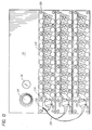
- Figure 2 is a front view of the manifold showing the surface on which the valve blocks are to be mounted. As can be seen, there are three horizontal rows of ten exit apertures 30 each having upper 31 and lower 32 semi circular segments separated by a divider 33. The upper exit apertures 31 of each row communicate with a horizontally extending internal chamber 34 which is supplied with high pressure air.
- Figure 3 shows how high pressure air is fed through an opening 35 in the base 36 into a vertically extending channel 37 which communicates with these high pressure chambers 34.
- the lower exit apertures 32 of the upper two rows communicate with horizontally extending internal chambers 38 which are supplied with low pressure air.
- Figure 3 also shows how low pressure air is fed through a base opening 39 into a vertically extending channel 40 which communicates with these low pressure chambers 38.
- This vertical low pressure channel 40 also communicates with a horizontally extending chamber 42 which communicates with the two low pressure exit apertures on the right hand end of the lowermost row.
- a separate chamber 44 communicates with the lower exit apertures of the two left hand apertures in the lowermost row and this chamber also is in communication with the low pressure vertical channel 40.
- each of the central six apertures of the lowermost row communicates with its own vertical channel 50.
- These channels have a normally open opening 51 at the bottom and a pair of aligned holes 52, 53 in the front 54 and rear 55 channel walls.
- These inlets 51 can accordingly be connected to a unique pressure such as plunger up pressure P4 or counterblow pressure P5.
- a unique pressure such as plunger up pressure P4 or counterblow pressure P5.
- six special conduits are provided for the three plunger up lines and the three counterblow lines.
- the bottom holes 51 to these six (or any of them) can be plugged and the plugs in the rear walls 55 can be removed (access by removing the plug in the front wall) so that low pressure air from a chamber 58 which is located behind these channels 50 and which communicates with the low pressure vertical channel 40, will enter these individual chambers 50 to supply the lower apertures with low pressure air.
- Pilot air (P3) is supplied to the valve blocks through piping 60 having an exit port 62 for each block and exhaust air exhausted from each block will be exhausted through a vertical exhaust channel 64.
- conduit 70 ( Figures 4 and 5) having an aperture 72 communicating with the front surface of the manifold and an aperture 74 communicating with one of the rear surfaces 13A, 13B of the manifold that will engage a kiss plate 13.
- the manifold ( Figure 2) also has an opening 76 at the bottom front left which will receive an electronic receptacle with the cable passing through a channel in the manifold up to the top chamber 78 so that the cable can be fed into the console through an opening at the rear of the console. Gaskets located between the mating surfaces of the kiss plates and the manifold and between the manifold and the valve blocks will effect the desired air tight seals.
- each valve block 20 Associated with each row of ten exit apertures 30 is a valve block 20 having corresponding inlet apertures.
- each valve block includes inlet apertures 80 having upper 81 and lower 82 semi circular segments separated by a divider 83, an inlet exit aperture 84, an exhaust channel 85 and a pilot bore 86 which will communicate respectively with the matched exit apertures 30, inlet/exit aperture 72, pilot exit port 62 and exhaust channel 64 of the manifold.
- the divider has two through holes 88 which receive end pins 89 secured to the resilient end cap 90 of the cylindrical sleeve 91 of a cartridge valve ( Figures 7 and 8).
- the sleeve is received by a suitable blind bore 92 in the valve block body 93 of a valve block 20.
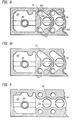
- the valve sleeve 91 can be oriented with the inlet aperture 94, which is a circular segment matching a circular segment 81, 82 of the inlet aperture 80 of the block, either in communication with the low pressure inlet aperture 82 as shown or the cartridge can be rotated 180° with the pins 89 again inserted into the divider holes 88 to locate this inlet aperture 94 in communication with the high pressure inlet aperture 81.
- a chamber is accordingly defined including the aperture 94 in the end cap 90, the aligned hole 81 or 82 in the valve block and an internal cavity 95 in the sleeve 91.
- the cartridge valve will accordingly supply either high or low pressure air to a supply port 96 which is controlled by a solenoid 98 which is mounted on the solenoid mounting block portion 99 of the valve block.
- the solenoid mounting block portion clamps the cartridge valve within the blind bore 92 and hence, forces the resilient end cap 90 against the end of the blind bore to seal the operative inlet opening 81 or 82.
- the pilot air bore 86 extends through the valve block body and communicates with a pilot air line 100 in the solenoid mounting block portion which communicates with an air line 101 communicating with each cartridge valve via a solenoid 98 controlled seal 102. Should the illustrated pilot operated solenoids be replaced with solenoids not requiring pilot air, these pilot air lines could be eliminated.
- valve as used might be a normally open valve.
- Flow through these parallel conduits 110 can be controlled in a conventional manner with the use of full or half plugs and meter in or out check valves in one of these conduits and the selective use of a half plug or a needle valve, where required, in the other conduit.
- each valve-block can be quickly and easily replaced with an identically configured valve block in the event a failure occurs.
- Each valve block is secured to the manifold with bolts 130 so that mechanical separation is quick and simple.
- the solenoids for each block are wired from a receptacle 132 secured to the block wiring harness 134.
- Electrical connection to the console is effected with a single quick release coupling 136 which can be released from the console and the three individual couplings 138 can be quickly released from the three valve block receptacles 132.
Landscapes
- Engineering & Computer Science (AREA)
- Mechanical Engineering (AREA)
- General Engineering & Computer Science (AREA)
- Chemical & Material Sciences (AREA)
- Manufacturing & Machinery (AREA)
- Materials Engineering (AREA)
- Organic Chemistry (AREA)
- Physics & Mathematics (AREA)
- Electromagnetism (AREA)
- Valve Housings (AREA)
- Multiple-Way Valves (AREA)
- Magnetically Actuated Valves (AREA)
Claims (7)
- Ventilblockanordnung zum Steuern der Luftströmung bei jedem von zwei Drücken zu luftbetriebenen Mechanismen einer Sektion einer IS-Maschine, umfassend:einen Verteiler (18),einen Ventilblockkörper (93), der am Verteiler gesichert ist und eine Vielzahl von Bohrungen (92) aufweist,eine Vielzahl von Ventilen, die von den Bohrungen (92) aufgenommen werden und jeweils eine zylindrische Hülse (91) und ein Ventilelement (105) haben, das axial in der zylindrischen Hülse (91) zwischen ersten und zweiten Steuerpositionen verschiebbar ist, wobeijede Ventilhülse (91) an einem Ende geschlossen ist und eine Öffnung (94) hat, die sich durch das geschlossene Ende erstreckt und durch die dem Ventil Druckluft zugeführt werden kann, wobei die Öffnung (94) so ausgestaltet ist, daß die Hülse (91) zwei Orientierungen annehmen kann, die gewählt werden, um getrennte Öffnungsorte zu definieren, wobeider Verteiler (18)eine erste Leitung (31, 34) zum Beliefern des Ventils mit Luft mit einem Druck umfaßt, die mit den Öffnungen (94) in Verbindung steht, wenn eine Hülse eine der Orientierungen annimmt,und eine zweite Leitung (32, 38) zum Beliefern des Ventils mit Luft mit einem anderen Druck, die mit der Öffnung (94) in Verbindung steht, wenn eine Hülse die zweite Orientierung annimmt.
- Ventiblockanordnung nach Anspruch 1, weiterhin umfassend eine Einrichtung (88, 89), die jede der Ventilhülsen (91) in einer der beiden Orientierungen innerhalb der Bohrungen hält.
- Ventilblockanordnung nach Anspruch 2, wobei die Vielzahl von Bohrungen (92) in einer horizontalen Reihe im Ventilblockkörper (93) angeordnet ist.
- Ventilblockanordnung nach einem der Ansprüche 2 oder 3, wobei jede Ventilkörperbohrung (92) eine Blindbohrung ist und erste und zweite Öffnungen (81, 82) im Blindende der Bohrung definiert sind, wobei die erste Öffnung (81) mit der Hülsenöffnung (94) in Verbindung steht, wenn die Hülse (91) eine der beiden Orientierungen annimmt, und die zweite Öffnung (82) mit der Hülsenöffnung (94) in Verbindung steht, wenn die Hülse (91) die andere der Orientierungen annimmt.
- Ventilblockanordnung nach Anspruch 4, wobei jede Hülse (91) ein Paar von Stiften (89) umfaßt, die axial vom geschlossenen Ende der Blindbohrung zwischen der ersten und zweiten Öffnung (81, 82) vorstehen, und ein Paar von Löchern zum Aufnehmen der Stifte in jeder der Orientierungen der zylindrischen Hülse.
- Ventilblockanordnung nach Anspruch 4, wobei die erste und zweite Leitungseinrichtung des Verteilers (18) sich horizontal erstreckende benachbarte Kammern umfassen, wobei eine der Kammern (38) eine Vielzahl von Ausgangsöffnungen (31) aufweist, die mit den ersten Ventilblockkörperöffnungen (81) in Verbindung stehen, und die zweite der Kammern (38) eine Vielzahl von Ausgangsöffnungen (32), die mit den zweiten Ventilblockkörperöffnungen (82) in Verbindung stehen.
- Ventilblockanordnung nach Anspruch 1,wobei die zweite Leitungseinrichtung des Verteilers (8) mindestens einen Kanalabschnitt (50) zum Zuführen von Luft mit unterschiedlichem Druck an die Ventile umfaßt, wobei der Verteiler (18) weiterhineine dritte Leitungseinrichtung (51) für die Zufuhr von Luft mit einem dritten Druck umfaßt, sowieeine Einrichtung (52, 53, 56) zum wahlweisen Blockieren der Luftströmung mit den unterschiedlichen Drücken durch mindestens einen der Kanalabschnitte (50) und zum Erstellen einer Verbindung zwischen der dritten Leitungseinrichtung (50) und jedem der blockierten Kanalabschnitte stromabwärts von der Blockiereinrichtung.
Applications Claiming Priority (2)
| Application Number | Priority Date | Filing Date | Title |
|---|---|---|---|
| US08/047,968 US5320130A (en) | 1993-04-15 | 1993-04-15 | Valve block assembly for I.S. machine |
| US47968 | 1993-04-15 |
Publications (3)
| Publication Number | Publication Date |
|---|---|
| EP0620198A2 EP0620198A2 (de) | 1994-10-19 |
| EP0620198A3 EP0620198A3 (de) | 1996-02-28 |
| EP0620198B1 true EP0620198B1 (de) | 2000-05-24 |
Family
ID=21952040
Family Applications (1)
| Application Number | Title | Priority Date | Filing Date |
|---|---|---|---|
| EP94302636A Expired - Lifetime EP0620198B1 (de) | 1993-04-15 | 1994-04-13 | Ventilblockvorrichtung für I.S. Maschinen |
Country Status (4)
| Country | Link |
|---|---|
| US (1) | US5320130A (de) |
| EP (1) | EP0620198B1 (de) |
| JP (1) | JP3376084B2 (de) |
| DE (1) | DE69424594T2 (de) |
Families Citing this family (4)
| Publication number | Priority date | Publication date | Assignee | Title |
|---|---|---|---|---|
| IT1292757B1 (it) * | 1997-06-10 | 1999-02-11 | Bottero Spa | Metodo e gruppo valvolare elettropneumatico per alimentare aria in pressione ad una macchina formatrice, particolarmente per la |
| GB9809034D0 (en) * | 1998-04-29 | 1998-06-24 | Emhart Glass Mach Invest | Pneumatic cartridge valve |
| US6983623B2 (en) * | 2002-04-18 | 2006-01-10 | Sg Alternatives, Llc | Valve block assembly for I.S. glassware machine and modular pilot valve operated poppet valve assembly |
| JP5890984B2 (ja) * | 2011-08-30 | 2016-03-22 | 株式会社フジキン | 流体制御装置 |
Family Cites Families (8)
| Publication number | Priority date | Publication date | Assignee | Title |
|---|---|---|---|---|
| GB1415012A (en) * | 1972-06-23 | 1975-11-26 | Emhart Uk Ltd | Valve block |
| DE2752938C2 (de) * | 1977-11-26 | 1985-06-20 | Bürkert GmbH, 7118 Ingelfingen | Steuerventilanordnung für zahnärztliche Geräte |
| US4382451A (en) * | 1979-02-16 | 1983-05-10 | Ball Corporation | Electronic valve assembly for glassware forming machinery |
| MX152277A (es) * | 1980-12-16 | 1985-06-19 | Vitro Tec Fideicomiso | Mejoras en bloque de valvulas neumaticas de solenoide para maquinas de fabricacion de articulos de vidrio |
| US4362544A (en) * | 1981-07-24 | 1982-12-07 | Owens-Illinois, Inc. | Fluid control system for glassware forming machine |
| DE3418933A1 (de) * | 1984-05-22 | 1985-11-28 | Robert Bosch Gmbh, 7000 Stuttgart | Steuerventil |
| IT1236747B (it) * | 1989-12-21 | 1993-03-31 | Blocco valvole elettropneumatico per macchine formatrici di oggetti in vetro cavo | |
| US5111840A (en) * | 1991-03-14 | 1992-05-12 | Applied Power Inc. | Modular valve |
-
1993
- 1993-04-15 US US08/047,968 patent/US5320130A/en not_active Expired - Lifetime
-
1994
- 1994-04-13 DE DE69424594T patent/DE69424594T2/de not_active Expired - Lifetime
- 1994-04-13 EP EP94302636A patent/EP0620198B1/de not_active Expired - Lifetime
- 1994-04-14 JP JP07614694A patent/JP3376084B2/ja not_active Expired - Fee Related
Also Published As
| Publication number | Publication date |
|---|---|
| US5320130A (en) | 1994-06-14 |
| DE69424594D1 (de) | 2000-06-29 |
| DE69424594T2 (de) | 2000-09-21 |
| JPH0712261A (ja) | 1995-01-17 |
| EP0620198A3 (de) | 1996-02-28 |
| JP3376084B2 (ja) | 2003-02-10 |
| EP0620198A2 (de) | 1994-10-19 |
Similar Documents
| Publication | Publication Date | Title |
|---|---|---|
| US5531249A (en) | Valve block assembly for I.S. machine | |
| US5178191A (en) | Modular pneumatic control systems | |
| US4230143A (en) | Control valve arrangement for dental equipment | |
| US5704399A (en) | Chained multiple connection change-over valve assembly | |
| US5660369A (en) | Pneumatic control device for needle valves in injection molding systems | |
| US4760961A (en) | Modular sprayhead assembly | |
| EP0620198B1 (de) | Ventilblockvorrichtung für I.S. Maschinen | |
| JPH11512168A (ja) | 電磁的に操作可能な空気式の方向制御弁 | |
| US5586570A (en) | Directional control valve | |
| EP0621243B1 (de) | Ventilblock für eine I.S.-Maschine | |
| US5996629A (en) | Pilot solenoid valve | |
| EP0915259A3 (de) | Verbindungseinrichtung für ein Wegeventil | |
| US3158164A (en) | Multiple block fluid distribution panel for mounting fluid control devices and method of directing fluid flow through the blocks | |
| EP0675083A2 (de) | Ventilblock für I.S. Maschinen | |
| CN107816570A (zh) | 流体分配器装置 | |
| USRE31529E (en) | Electronic valve assembly for glassware forming machinery | |
| US8926303B2 (en) | Valve assembly for an injection molding machine | |
| US4382451A (en) | Electronic valve assembly for glassware forming machinery | |
| EP0911559B1 (de) | Vorgesteuertes Lenkungsregelventil | |
| US4293004A (en) | Electronic valve assembly for glassware forming machinery | |
| EP0620199A2 (de) | Modulare Bereichskontrolle für eine I.S. Maschine | |
| WO1992004568A1 (en) | Modular pneumatic control systems | |
| EP0800002A1 (de) | Elektromagnetisch betätiges Steuerventil | |
| JPH01216174A (ja) | シャトル弁装置 | |
| EP0620194B1 (de) | Maschine zum Herstellen von Glasgegenständen |
Legal Events
| Date | Code | Title | Description |
|---|---|---|---|
| PUAI | Public reference made under article 153(3) epc to a published international application that has entered the european phase |
Free format text: ORIGINAL CODE: 0009012 |
|
| AK | Designated contracting states |
Kind code of ref document: A2 Designated state(s): DE FR GB IT |
|
| PUAL | Search report despatched |
Free format text: ORIGINAL CODE: 0009013 |
|
| AK | Designated contracting states |
Kind code of ref document: A3 Designated state(s): DE FR GB IT |
|
| 17P | Request for examination filed |
Effective date: 19960615 |
|
| 17Q | First examination report despatched |
Effective date: 19980616 |
|
| GRAG | Despatch of communication of intention to grant |
Free format text: ORIGINAL CODE: EPIDOS AGRA |
|
| GRAG | Despatch of communication of intention to grant |
Free format text: ORIGINAL CODE: EPIDOS AGRA |
|
| GRAH | Despatch of communication of intention to grant a patent |
Free format text: ORIGINAL CODE: EPIDOS IGRA |
|
| GRAH | Despatch of communication of intention to grant a patent |
Free format text: ORIGINAL CODE: EPIDOS IGRA |
|
| GRAA | (expected) grant |
Free format text: ORIGINAL CODE: 0009210 |
|
| AK | Designated contracting states |
Kind code of ref document: B1 Designated state(s): DE FR GB IT |
|
| REF | Corresponds to: |
Ref document number: 69424594 Country of ref document: DE Date of ref document: 20000629 |
|
| ITF | It: translation for a ep patent filed | ||
| ET | Fr: translation filed | ||
| RAP2 | Party data changed (patent owner data changed or rights of a patent transferred) |
Owner name: EMHART GLASS S.A. |
|
| PLBE | No opposition filed within time limit |
Free format text: ORIGINAL CODE: 0009261 |
|
| STAA | Information on the status of an ep patent application or granted ep patent |
Free format text: STATUS: NO OPPOSITION FILED WITHIN TIME LIMIT |
|
| 26N | No opposition filed | ||
| REG | Reference to a national code |
Ref country code: FR Ref legal event code: TP |
|
| REG | Reference to a national code |
Ref country code: GB Ref legal event code: IF02 |
|
| PGFP | Annual fee paid to national office [announced via postgrant information from national office to epo] |
Ref country code: FR Payment date: 20100506 Year of fee payment: 17 |
|
| PGFP | Annual fee paid to national office [announced via postgrant information from national office to epo] |
Ref country code: IT Payment date: 20100428 Year of fee payment: 17 Ref country code: DE Payment date: 20100428 Year of fee payment: 17 |
|
| PGFP | Annual fee paid to national office [announced via postgrant information from national office to epo] |
Ref country code: GB Payment date: 20100426 Year of fee payment: 17 |
|
| REG | Reference to a national code |
Ref country code: DE Ref legal event code: R119 Ref document number: 69424594 Country of ref document: DE |
|
| REG | Reference to a national code |
Ref country code: DE Ref legal event code: R119 Ref document number: 69424594 Country of ref document: DE |
|
| GBPC | Gb: european patent ceased through non-payment of renewal fee |
Effective date: 20110413 |
|
| REG | Reference to a national code |
Ref country code: FR Ref legal event code: ST Effective date: 20111230 |
|
| PG25 | Lapsed in a contracting state [announced via postgrant information from national office to epo] |
Ref country code: FR Free format text: LAPSE BECAUSE OF NON-PAYMENT OF DUE FEES Effective date: 20110502 |
|
| PG25 | Lapsed in a contracting state [announced via postgrant information from national office to epo] |
Ref country code: GB Free format text: LAPSE BECAUSE OF NON-PAYMENT OF DUE FEES Effective date: 20110413 Ref country code: IT Free format text: LAPSE BECAUSE OF NON-PAYMENT OF DUE FEES Effective date: 20110413 |
|
| PG25 | Lapsed in a contracting state [announced via postgrant information from national office to epo] |
Ref country code: DE Free format text: LAPSE BECAUSE OF NON-PAYMENT OF DUE FEES Effective date: 20111031 |