EP0620107A2 - Verfahren und Vorrichtung zur Herstellung eines Formteiles aus Kunststoff, sowie das durch das Verfahren hergestellte Formteil - Google Patents
Verfahren und Vorrichtung zur Herstellung eines Formteiles aus Kunststoff, sowie das durch das Verfahren hergestellte Formteil Download PDFInfo
- Publication number
- EP0620107A2 EP0620107A2 EP94102133A EP94102133A EP0620107A2 EP 0620107 A2 EP0620107 A2 EP 0620107A2 EP 94102133 A EP94102133 A EP 94102133A EP 94102133 A EP94102133 A EP 94102133A EP 0620107 A2 EP0620107 A2 EP 0620107A2
- Authority
- EP
- European Patent Office
- Prior art keywords
- tubular part
- pipe socket
- bolt
- valve housing
- welding
- Prior art date
- Legal status (The legal status is an assumption and is not a legal conclusion. Google has not performed a legal analysis and makes no representation as to the accuracy of the status listed.)
- Granted
Links
Images

Classifications
-
- B—PERFORMING OPERATIONS; TRANSPORTING
- B29—WORKING OF PLASTICS; WORKING OF SUBSTANCES IN A PLASTIC STATE IN GENERAL
- B29D—PRODUCING PARTICULAR ARTICLES FROM PLASTICS OR FROM SUBSTANCES IN A PLASTIC STATE
- B29D23/00—Producing tubular articles
- B29D23/001—Pipes; Pipe joints
- B29D23/003—Pipe joints, e.g. straight joints
- B29D23/008—T-joints
-
- B—PERFORMING OPERATIONS; TRANSPORTING
- B29—WORKING OF PLASTICS; WORKING OF SUBSTANCES IN A PLASTIC STATE IN GENERAL
- B29C—SHAPING OR JOINING OF PLASTICS; SHAPING OF MATERIAL IN A PLASTIC STATE, NOT OTHERWISE PROVIDED FOR; AFTER-TREATMENT OF THE SHAPED PRODUCTS, e.g. REPAIRING
- B29C65/00—Joining or sealing of preformed parts, e.g. welding of plastics materials; Apparatus therefor
- B29C65/02—Joining or sealing of preformed parts, e.g. welding of plastics materials; Apparatus therefor by heating, with or without pressure
- B29C65/14—Joining or sealing of preformed parts, e.g. welding of plastics materials; Apparatus therefor by heating, with or without pressure using wave energy, i.e. electromagnetic radiation, or particle radiation
- B29C65/1429—Joining or sealing of preformed parts, e.g. welding of plastics materials; Apparatus therefor by heating, with or without pressure using wave energy, i.e. electromagnetic radiation, or particle radiation characterised by the way of heating the interface
- B29C65/1432—Joining or sealing of preformed parts, e.g. welding of plastics materials; Apparatus therefor by heating, with or without pressure using wave energy, i.e. electromagnetic radiation, or particle radiation characterised by the way of heating the interface direct heating of the surfaces to be joined
-
- B—PERFORMING OPERATIONS; TRANSPORTING
- B29—WORKING OF PLASTICS; WORKING OF SUBSTANCES IN A PLASTIC STATE IN GENERAL
- B29C—SHAPING OR JOINING OF PLASTICS; SHAPING OF MATERIAL IN A PLASTIC STATE, NOT OTHERWISE PROVIDED FOR; AFTER-TREATMENT OF THE SHAPED PRODUCTS, e.g. REPAIRING
- B29C65/00—Joining or sealing of preformed parts, e.g. welding of plastics materials; Apparatus therefor
- B29C65/02—Joining or sealing of preformed parts, e.g. welding of plastics materials; Apparatus therefor by heating, with or without pressure
- B29C65/18—Joining or sealing of preformed parts, e.g. welding of plastics materials; Apparatus therefor by heating, with or without pressure using heated tools
- B29C65/20—Joining or sealing of preformed parts, e.g. welding of plastics materials; Apparatus therefor by heating, with or without pressure using heated tools with direct contact, e.g. using "mirror"
-
- B—PERFORMING OPERATIONS; TRANSPORTING
- B29—WORKING OF PLASTICS; WORKING OF SUBSTANCES IN A PLASTIC STATE IN GENERAL
- B29C—SHAPING OR JOINING OF PLASTICS; SHAPING OF MATERIAL IN A PLASTIC STATE, NOT OTHERWISE PROVIDED FOR; AFTER-TREATMENT OF THE SHAPED PRODUCTS, e.g. REPAIRING
- B29C65/00—Joining or sealing of preformed parts, e.g. welding of plastics materials; Apparatus therefor
- B29C65/78—Means for handling the parts to be joined, e.g. for making containers or hollow articles, e.g. means for handling sheets, plates, web-like materials, tubular articles, hollow articles or elements to be joined therewith; Means for discharging the joined articles from the joining apparatus
- B29C65/7802—Positioning the parts to be joined, e.g. aligning, indexing or centring
-
- B—PERFORMING OPERATIONS; TRANSPORTING
- B29—WORKING OF PLASTICS; WORKING OF SUBSTANCES IN A PLASTIC STATE IN GENERAL
- B29C—SHAPING OR JOINING OF PLASTICS; SHAPING OF MATERIAL IN A PLASTIC STATE, NOT OTHERWISE PROVIDED FOR; AFTER-TREATMENT OF THE SHAPED PRODUCTS, e.g. REPAIRING
- B29C66/00—General aspects of processes or apparatus for joining preformed parts
- B29C66/01—General aspects dealing with the joint area or with the area to be joined
- B29C66/05—Particular design of joint configurations
- B29C66/10—Particular design of joint configurations particular design of the joint cross-sections
- B29C66/11—Joint cross-sections comprising a single joint-segment, i.e. one of the parts to be joined comprising a single joint-segment in the joint cross-section
- B29C66/112—Single lapped joints
-
- B—PERFORMING OPERATIONS; TRANSPORTING
- B29—WORKING OF PLASTICS; WORKING OF SUBSTANCES IN A PLASTIC STATE IN GENERAL
- B29C—SHAPING OR JOINING OF PLASTICS; SHAPING OF MATERIAL IN A PLASTIC STATE, NOT OTHERWISE PROVIDED FOR; AFTER-TREATMENT OF THE SHAPED PRODUCTS, e.g. REPAIRING
- B29C66/00—General aspects of processes or apparatus for joining preformed parts
- B29C66/01—General aspects dealing with the joint area or with the area to be joined
- B29C66/05—Particular design of joint configurations
- B29C66/10—Particular design of joint configurations particular design of the joint cross-sections
- B29C66/11—Joint cross-sections comprising a single joint-segment, i.e. one of the parts to be joined comprising a single joint-segment in the joint cross-section
- B29C66/116—Single bevelled joints, i.e. one of the parts to be joined being bevelled in the joint area
- B29C66/1162—Single bevel to bevel joints, e.g. mitre joints
-
- B—PERFORMING OPERATIONS; TRANSPORTING
- B29—WORKING OF PLASTICS; WORKING OF SUBSTANCES IN A PLASTIC STATE IN GENERAL
- B29C—SHAPING OR JOINING OF PLASTICS; SHAPING OF MATERIAL IN A PLASTIC STATE, NOT OTHERWISE PROVIDED FOR; AFTER-TREATMENT OF THE SHAPED PRODUCTS, e.g. REPAIRING
- B29C66/00—General aspects of processes or apparatus for joining preformed parts
- B29C66/01—General aspects dealing with the joint area or with the area to be joined
- B29C66/05—Particular design of joint configurations
- B29C66/301—Three-dimensional joints, i.e. the joined area being substantially non-flat
-
- B—PERFORMING OPERATIONS; TRANSPORTING
- B29—WORKING OF PLASTICS; WORKING OF SUBSTANCES IN A PLASTIC STATE IN GENERAL
- B29C—SHAPING OR JOINING OF PLASTICS; SHAPING OF MATERIAL IN A PLASTIC STATE, NOT OTHERWISE PROVIDED FOR; AFTER-TREATMENT OF THE SHAPED PRODUCTS, e.g. REPAIRING
- B29C66/00—General aspects of processes or apparatus for joining preformed parts
- B29C66/50—General aspects of joining tubular articles; General aspects of joining long products, i.e. bars or profiled elements; General aspects of joining single elements to tubular articles, hollow articles or bars; General aspects of joining several hollow-preforms to form hollow or tubular articles
- B29C66/51—Joining tubular articles, profiled elements or bars; Joining single elements to tubular articles, hollow articles or bars; Joining several hollow-preforms to form hollow or tubular articles
- B29C66/52—Joining tubular articles, bars or profiled elements
- B29C66/522—Joining tubular articles
- B29C66/5224—Joining tubular articles for forming fork-shaped connections, e.g. for making Y-shaped pieces
- B29C66/52241—Joining tubular articles for forming fork-shaped connections, e.g. for making Y-shaped pieces with two right angles, e.g. for making T-shaped pieces
-
- B—PERFORMING OPERATIONS; TRANSPORTING
- B29—WORKING OF PLASTICS; WORKING OF SUBSTANCES IN A PLASTIC STATE IN GENERAL
- B29C—SHAPING OR JOINING OF PLASTICS; SHAPING OF MATERIAL IN A PLASTIC STATE, NOT OTHERWISE PROVIDED FOR; AFTER-TREATMENT OF THE SHAPED PRODUCTS, e.g. REPAIRING
- B29C66/00—General aspects of processes or apparatus for joining preformed parts
- B29C66/50—General aspects of joining tubular articles; General aspects of joining long products, i.e. bars or profiled elements; General aspects of joining single elements to tubular articles, hollow articles or bars; General aspects of joining several hollow-preforms to form hollow or tubular articles
- B29C66/63—Internally supporting the article during joining
-
- B—PERFORMING OPERATIONS; TRANSPORTING
- B29—WORKING OF PLASTICS; WORKING OF SUBSTANCES IN A PLASTIC STATE IN GENERAL
- B29C—SHAPING OR JOINING OF PLASTICS; SHAPING OF MATERIAL IN A PLASTIC STATE, NOT OTHERWISE PROVIDED FOR; AFTER-TREATMENT OF THE SHAPED PRODUCTS, e.g. REPAIRING
- B29C66/00—General aspects of processes or apparatus for joining preformed parts
- B29C66/80—General aspects of machine operations or constructions and parts thereof
- B29C66/81—General aspects of the pressing elements, i.e. the elements applying pressure on the parts to be joined in the area to be joined, e.g. the welding jaws or clamps
- B29C66/814—General aspects of the pressing elements, i.e. the elements applying pressure on the parts to be joined in the area to be joined, e.g. the welding jaws or clamps characterised by the design of the pressing elements, e.g. of the welding jaws or clamps
- B29C66/8141—General aspects of the pressing elements, i.e. the elements applying pressure on the parts to be joined in the area to be joined, e.g. the welding jaws or clamps characterised by the design of the pressing elements, e.g. of the welding jaws or clamps characterised by the surface geometry of the part of the pressing elements, e.g. welding jaws or clamps, coming into contact with the parts to be joined
- B29C66/81411—General aspects of the pressing elements, i.e. the elements applying pressure on the parts to be joined in the area to be joined, e.g. the welding jaws or clamps characterised by the design of the pressing elements, e.g. of the welding jaws or clamps characterised by the surface geometry of the part of the pressing elements, e.g. welding jaws or clamps, coming into contact with the parts to be joined characterised by its cross-section, e.g. transversal or longitudinal, being non-flat
- B29C66/81421—General aspects of the pressing elements, i.e. the elements applying pressure on the parts to be joined in the area to be joined, e.g. the welding jaws or clamps characterised by the design of the pressing elements, e.g. of the welding jaws or clamps characterised by the surface geometry of the part of the pressing elements, e.g. welding jaws or clamps, coming into contact with the parts to be joined characterised by its cross-section, e.g. transversal or longitudinal, being non-flat being convex or concave
- B29C66/81422—General aspects of the pressing elements, i.e. the elements applying pressure on the parts to be joined in the area to be joined, e.g. the welding jaws or clamps characterised by the design of the pressing elements, e.g. of the welding jaws or clamps characterised by the surface geometry of the part of the pressing elements, e.g. welding jaws or clamps, coming into contact with the parts to be joined characterised by its cross-section, e.g. transversal or longitudinal, being non-flat being convex or concave being convex
-
- B—PERFORMING OPERATIONS; TRANSPORTING
- B29—WORKING OF PLASTICS; WORKING OF SUBSTANCES IN A PLASTIC STATE IN GENERAL
- B29C—SHAPING OR JOINING OF PLASTICS; SHAPING OF MATERIAL IN A PLASTIC STATE, NOT OTHERWISE PROVIDED FOR; AFTER-TREATMENT OF THE SHAPED PRODUCTS, e.g. REPAIRING
- B29C66/00—General aspects of processes or apparatus for joining preformed parts
- B29C66/80—General aspects of machine operations or constructions and parts thereof
- B29C66/81—General aspects of the pressing elements, i.e. the elements applying pressure on the parts to be joined in the area to be joined, e.g. the welding jaws or clamps
- B29C66/814—General aspects of the pressing elements, i.e. the elements applying pressure on the parts to be joined in the area to be joined, e.g. the welding jaws or clamps characterised by the design of the pressing elements, e.g. of the welding jaws or clamps
- B29C66/8141—General aspects of the pressing elements, i.e. the elements applying pressure on the parts to be joined in the area to be joined, e.g. the welding jaws or clamps characterised by the design of the pressing elements, e.g. of the welding jaws or clamps characterised by the surface geometry of the part of the pressing elements, e.g. welding jaws or clamps, coming into contact with the parts to be joined
- B29C66/81411—General aspects of the pressing elements, i.e. the elements applying pressure on the parts to be joined in the area to be joined, e.g. the welding jaws or clamps characterised by the design of the pressing elements, e.g. of the welding jaws or clamps characterised by the surface geometry of the part of the pressing elements, e.g. welding jaws or clamps, coming into contact with the parts to be joined characterised by its cross-section, e.g. transversal or longitudinal, being non-flat
- B29C66/81421—General aspects of the pressing elements, i.e. the elements applying pressure on the parts to be joined in the area to be joined, e.g. the welding jaws or clamps characterised by the design of the pressing elements, e.g. of the welding jaws or clamps characterised by the surface geometry of the part of the pressing elements, e.g. welding jaws or clamps, coming into contact with the parts to be joined characterised by its cross-section, e.g. transversal or longitudinal, being non-flat being convex or concave
- B29C66/81423—General aspects of the pressing elements, i.e. the elements applying pressure on the parts to be joined in the area to be joined, e.g. the welding jaws or clamps characterised by the design of the pressing elements, e.g. of the welding jaws or clamps characterised by the surface geometry of the part of the pressing elements, e.g. welding jaws or clamps, coming into contact with the parts to be joined characterised by its cross-section, e.g. transversal or longitudinal, being non-flat being convex or concave being concave
-
- B—PERFORMING OPERATIONS; TRANSPORTING
- B29—WORKING OF PLASTICS; WORKING OF SUBSTANCES IN A PLASTIC STATE IN GENERAL
- B29C—SHAPING OR JOINING OF PLASTICS; SHAPING OF MATERIAL IN A PLASTIC STATE, NOT OTHERWISE PROVIDED FOR; AFTER-TREATMENT OF THE SHAPED PRODUCTS, e.g. REPAIRING
- B29C66/00—General aspects of processes or apparatus for joining preformed parts
- B29C66/80—General aspects of machine operations or constructions and parts thereof
- B29C66/83—General aspects of machine operations or constructions and parts thereof characterised by the movement of the joining or pressing tools
- B29C66/832—Reciprocating joining or pressing tools
- B29C66/8322—Joining or pressing tools reciprocating along one axis
-
- B—PERFORMING OPERATIONS; TRANSPORTING
- B29—WORKING OF PLASTICS; WORKING OF SUBSTANCES IN A PLASTIC STATE IN GENERAL
- B29C—SHAPING OR JOINING OF PLASTICS; SHAPING OF MATERIAL IN A PLASTIC STATE, NOT OTHERWISE PROVIDED FOR; AFTER-TREATMENT OF THE SHAPED PRODUCTS, e.g. REPAIRING
- B29C66/00—General aspects of processes or apparatus for joining preformed parts
- B29C66/80—General aspects of machine operations or constructions and parts thereof
- B29C66/84—Specific machine types or machines suitable for specific applications
- B29C66/861—Hand-held tools
-
- B—PERFORMING OPERATIONS; TRANSPORTING
- B29—WORKING OF PLASTICS; WORKING OF SUBSTANCES IN A PLASTIC STATE IN GENERAL
- B29C—SHAPING OR JOINING OF PLASTICS; SHAPING OF MATERIAL IN A PLASTIC STATE, NOT OTHERWISE PROVIDED FOR; AFTER-TREATMENT OF THE SHAPED PRODUCTS, e.g. REPAIRING
- B29C65/00—Joining or sealing of preformed parts, e.g. welding of plastics materials; Apparatus therefor
- B29C65/02—Joining or sealing of preformed parts, e.g. welding of plastics materials; Apparatus therefor by heating, with or without pressure
- B29C65/14—Joining or sealing of preformed parts, e.g. welding of plastics materials; Apparatus therefor by heating, with or without pressure using wave energy, i.e. electromagnetic radiation, or particle radiation
- B29C65/1403—Joining or sealing of preformed parts, e.g. welding of plastics materials; Apparatus therefor by heating, with or without pressure using wave energy, i.e. electromagnetic radiation, or particle radiation characterised by the type of electromagnetic or particle radiation
- B29C65/1412—Infrared [IR] radiation
-
- B—PERFORMING OPERATIONS; TRANSPORTING
- B29—WORKING OF PLASTICS; WORKING OF SUBSTANCES IN A PLASTIC STATE IN GENERAL
- B29C—SHAPING OR JOINING OF PLASTICS; SHAPING OF MATERIAL IN A PLASTIC STATE, NOT OTHERWISE PROVIDED FOR; AFTER-TREATMENT OF THE SHAPED PRODUCTS, e.g. REPAIRING
- B29C66/00—General aspects of processes or apparatus for joining preformed parts
- B29C66/70—General aspects of processes or apparatus for joining preformed parts characterised by the composition, physical properties or the structure of the material of the parts to be joined; Joining with non-plastics material
- B29C66/73—General aspects of processes or apparatus for joining preformed parts characterised by the composition, physical properties or the structure of the material of the parts to be joined; Joining with non-plastics material characterised by the intensive physical properties of the material of the parts to be joined, by the optical properties of the material of the parts to be joined, by the extensive physical properties of the parts to be joined, by the state of the material of the parts to be joined or by the material of the parts to be joined being a thermoplastic or a thermoset
- B29C66/739—General aspects of processes or apparatus for joining preformed parts characterised by the composition, physical properties or the structure of the material of the parts to be joined; Joining with non-plastics material characterised by the intensive physical properties of the material of the parts to be joined, by the optical properties of the material of the parts to be joined, by the extensive physical properties of the parts to be joined, by the state of the material of the parts to be joined or by the material of the parts to be joined being a thermoplastic or a thermoset characterised by the material of the parts to be joined being a thermoplastic or a thermoset
- B29C66/7392—General aspects of processes or apparatus for joining preformed parts characterised by the composition, physical properties or the structure of the material of the parts to be joined; Joining with non-plastics material characterised by the intensive physical properties of the material of the parts to be joined, by the optical properties of the material of the parts to be joined, by the extensive physical properties of the parts to be joined, by the state of the material of the parts to be joined or by the material of the parts to be joined being a thermoplastic or a thermoset characterised by the material of the parts to be joined being a thermoplastic or a thermoset characterised by the material of at least one of the parts being a thermoplastic
- B29C66/73921—General aspects of processes or apparatus for joining preformed parts characterised by the composition, physical properties or the structure of the material of the parts to be joined; Joining with non-plastics material characterised by the intensive physical properties of the material of the parts to be joined, by the optical properties of the material of the parts to be joined, by the extensive physical properties of the parts to be joined, by the state of the material of the parts to be joined or by the material of the parts to be joined being a thermoplastic or a thermoset characterised by the material of the parts to be joined being a thermoplastic or a thermoset characterised by the material of at least one of the parts being a thermoplastic characterised by the materials of both parts being thermoplastics
-
- Y—GENERAL TAGGING OF NEW TECHNOLOGICAL DEVELOPMENTS; GENERAL TAGGING OF CROSS-SECTIONAL TECHNOLOGIES SPANNING OVER SEVERAL SECTIONS OF THE IPC; TECHNICAL SUBJECTS COVERED BY FORMER USPC CROSS-REFERENCE ART COLLECTIONS [XRACs] AND DIGESTS
- Y10—TECHNICAL SUBJECTS COVERED BY FORMER USPC
- Y10T—TECHNICAL SUBJECTS COVERED BY FORMER US CLASSIFICATION
- Y10T137/00—Fluid handling
- Y10T137/0318—Processes
- Y10T137/0402—Cleaning, repairing, or assembling
- Y10T137/0491—Valve or valve element assembling, disassembling, or replacing
-
- Y—GENERAL TAGGING OF NEW TECHNOLOGICAL DEVELOPMENTS; GENERAL TAGGING OF CROSS-SECTIONAL TECHNOLOGIES SPANNING OVER SEVERAL SECTIONS OF THE IPC; TECHNICAL SUBJECTS COVERED BY FORMER USPC CROSS-REFERENCE ART COLLECTIONS [XRACs] AND DIGESTS
- Y10—TECHNICAL SUBJECTS COVERED BY FORMER USPC
- Y10T—TECHNICAL SUBJECTS COVERED BY FORMER US CLASSIFICATION
- Y10T137/00—Fluid handling
- Y10T137/598—With repair, tapping, assembly, or disassembly means
- Y10T137/60—Assembling or disassembling flexible tube or sleeve type valve
-
- Y—GENERAL TAGGING OF NEW TECHNOLOGICAL DEVELOPMENTS; GENERAL TAGGING OF CROSS-SECTIONAL TECHNOLOGIES SPANNING OVER SEVERAL SECTIONS OF THE IPC; TECHNICAL SUBJECTS COVERED BY FORMER USPC CROSS-REFERENCE ART COLLECTIONS [XRACs] AND DIGESTS
- Y10—TECHNICAL SUBJECTS COVERED BY FORMER USPC
- Y10T—TECHNICAL SUBJECTS COVERED BY FORMER US CLASSIFICATION
- Y10T137/00—Fluid handling
- Y10T137/8593—Systems
- Y10T137/85938—Non-valved flow dividers
Definitions
- the invention relates to a method for producing a molded part made of plastic as described in the preamble of claim 1, as well as a molded part produced by the method and a device required therefor.
- the object of the present invention is to create a method of the type mentioned at the outset and a device required for this, by means of which a firm welded connection can be produced without any additional requirement and means remaining on the connection.
- this object is achieved by the characterizing features of method claim 1, claim 3 a molded part produced by the method and the device claim 6 solved.
- the figures show a device for welding a tubular part 1 e.g. a piece of pipe made of plastic with a pipe socket 3 of a valve housing 2 e.g. a diaphragm valve.
- the valve housing 2 has a second pipe socket 4.
- the valve housing 2 is held firmly with the pipe socket 4 in a receiving device 5, the receiving device 5 being arranged on a displaceable carriage, not shown.
- Other molded parts having a pipe socket 3 can also be welded to one another with the tubular part 1 to form a molded part.
- the tubular part 1 is held in a form-fitting manner in a second receiving device 6.
- This has an outer support part 8 partially encompassing the outer circumference of the tubular part 1 and an inner support part 7 corresponding to the inner contour of the tubular part 1.
- a bolt 11, which can be displaced transversely to its longitudinal axis 9 by means of a wedge pull 10, is arranged on the inner support part 7.
- the wedge pull 10 consists of a rod 13 which can be displaced in a bore 12 of the inner support part 7 by means of a handle 14 and which has an inclined surface 15 against which the bolt 11 rests with an end-side inclined surface 16.
- the bolt 11 When the rod 13 is inserted, the bolt 11 is displaced so far through a bore 17 arranged in the tubular part 1 that it projects into the pipe socket 3 of the valve housing 2.
- the outside diameter of the bolt 12 corresponds to the inside diameter of the pipe socket 3.
- the bolt 11 To remove the welded parts, the bolt 11 must first be pushed back through the pipe socket 3. There is also the possibility of forming the wedge pull 10 by means of a corresponding positive connection between the rod 13 and the bolt 11, acting in both directions.
- a reciprocating piston drive can also be arranged for an automatic workflow.
- the device also has a heating device 20, which enables a contactless heating of the front end 18 of the pipe socket 3 and a part of the outer circumference of the tubular part 1 by means of infrared radiation.
- the heating device can be inserted or swung in between parts 1 and 3 and is then moved axially by means of the receiving device 5 to a corresponding distance for rapid heating of approximately 1 to 2 mm to the heating surfaces.
- the heating device has a concave radiation surface 21 corresponding to the outer circumference of the tubular part 1 and a convex radiation surface 22 corresponding to the front end 18 of the pipe socket 3. Both radiation surfaces are provided with centrally arranged round recesses 23, 24.
- the heater 20 is e.g. can be heated electrically with heating cartridges and is preferably made of copper, the radiating surfaces 21, 22 being coated with ceramic.
- the tubular part 1 is provided with the bore 17 and inserted into the receiving device 6 and the valve housing 2 with the pipe socket 4 is clamped into the receiving device 5 in the outer end position, the front end 18 of the pipe socket 3 already being formally matched to the outside diameter of the tubular part 1 is adjusted.
- the end 18 and an annular part of the outer circumference of the tubular part 1 are heated in the region of the bore 17 for plasticizing the plastic.
- the bolt 11 is pushed by means of the wedge pull 10 in the direction of its longitudinal axis 19 through the bore 17 and the valve housing 2 is pushed against the outer circumference of the tubular part 1 by moving the slide while simultaneously pushing the pipe socket 3 onto the bolt 11.
Landscapes
- Engineering & Computer Science (AREA)
- Mechanical Engineering (AREA)
- Physics & Mathematics (AREA)
- Health & Medical Sciences (AREA)
- Electromagnetism (AREA)
- Toxicology (AREA)
- Lining Or Joining Of Plastics Or The Like (AREA)
- Valve Housings (AREA)
- Vehicle Interior And Exterior Ornaments, Soundproofing, And Insulation (AREA)
- Diaphragms For Electromechanical Transducers (AREA)
- Extrusion Moulding Of Plastics Or The Like (AREA)
Abstract
Description
- Die Erfindung betrifft ein Verfahren zur Herstellung eines Formteiles aus Kunststoff wie es im Oberbegriff von Anspruch 1 beschrieben ist, sowie ein durch das Verfahren hergestelltes Formteil und eine dafür erforderliche Vorrichtung.
- Es ist bekannt Rohrstutzen für Abzweigleitungen mit Rohren an deren Aussenumfang zu verschweissen (z.B. CH-PS 570 577), wobei zwischen der Rohrleitung und einem Sattelteil des Rohrstutzen eine aus einem Widerstandsdraht bestehende Schweissmatte zur Erzeugung der Schweisstemperatur angeordnet ist. Derartige Schweissverfahren sind sehr aufwendig.
- Aufgabe der vorliegenden Erfindung ist die Schaffung eines Verfahrens der eingangs genannten Art und einer dafür erforderlichen Vorrichtung, mittels welchen eine feste Schweissverbindung ohne zusätzlich erforderlich und an der Verbindung verbleibende Mittel herstellbar ist.
- Erfindungsgemäss wird diese Aufgabe durch die kennzeichenden Merkmale des Verfahrensanspruches 1, des Anspruches 3 betreffend ein durch das Verfahren hergestellten Formteiles und des Vorrichtungsanspruches 6 gelöst.
- Besonders vorteilhafte Ausführungen sind in den davon abhängigen Ansprüchen gekennzeichnet.
- Die Erfindung ist in den beiliegenden Zeichnungen beispielsweise dargestellt und nachfolgend beschrieben. Es zeigen:
- Fig. 1
- einen Querschnitt durch eine Vorrichtung zum Verschweissen mit den zu verschweissenden Teilen in vereinfachter Darstellung
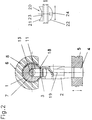
- Fig. 2
- einen Schnitt entlang der Linie II - II von Fig. 1.
- Die Figuren zeigen eine Vorrichtung zum Verschweissen eines rohrförmigen Teiles 1 z.B. eines Rohrstückes aus Kunststoff mit einem Rohrstutzen 3 eines Ventilgehäuses 2 z.B. eines Membranventiles. Das Ventilgehäuse 2 weist einen zweiten Rohrstutzen 4 auf. Das Ventilgehäuse 2 wird mit dem Rohrstutzen 4 in einer Aufnahmevorrichtung 5 fest gehalten, wobei die Aufnahmevorrichtung 5 auf einem weiter nicht dargestellten verschiebbaren Schlitten angeordnet ist. Es können auch andere einen Rohrstutzen 3 aufweisende Formteile mit dem rohrförmigen Teil 1 zu einem Formteil miteinander verschweisst werden.
- Das rohrförmige Teil 1 ist in einer zweiten Aufnahmevorrichtung 6 formschlüssig gehalten. Diese weist ein den Aussenumfang des rohrförmigen Teiles 1 teilweise umfassendes AussenAbstützteil 8 und ein der Innenkontur des rohrförmigen Teiles 1 entsprechendes Innen-Abstützteil 7 auf. Am Innen-Abstützteil 7 ist ein quer zu dessen Längsachse 9 mittels eines Keilzuges 10 verschiebbarer Bolzen 11 angeordnet. Der Keilzug 10 besteht aus einer in einer Bohrung 12 des Innen-Abstützteiles 7 mittels eines Handgriffes 14 verschiebbaren Stange 13 welche eine schräge Fläche 15 aufweist, an welche der Bolzen 11 mit einer stirnseitigen schrägen Fläche 16 anliegt.
- Beim Einschieben des Stange 13 wird der Bolzen 11 durch eine im rohrförmigen Teil 1 angeordnete Bohrung 17 so weit verschoben, dass er bis in den Rohrstutzen 3 des Ventilgehäuses 2 ragt. Der Aussendurchmesser des Bolzens 12 entspricht dem Innendurchmesser des Rohrstutzens 3.
- Zur Entnahme der geschweissten Teile muss vorher der Bolzen 11 durch den Rohrstutzen 3 zurückgestossen werden. Es besteht auch die Möglichkeit den Keilzug 10 durch eine entsprechende formschlüssige Verbindung zwischen der Stange 13 und dem Bolzen 11 in beide Richtungen wirkend auszubilden.
- An Stelle des Handgriffes 14 kann auch für einen automatischen Arbeitsablauf ein Hubkolbenantrieb angeordnet werden.
- Die Vorrichtung weist ferner eine Heizvorrichtung 20 auf, welche durch eine Infrarot-Strahlung ein berührungsloses Aufheizen des stirnseitigen Endes 18 des Rohrstutzens 3 und einen Teil des Aussenumfanges vom rohrförmigen Teil 1 ermöglicht. Die Heizvorrichtung ist zwischen die Teile 1 und 3 einschiebbar oder einschwenkbar und wird dann durch axiales Verschieben mittels der Aufnahmevorrichtung 5 auf für ein rasches Aufheizen entsprechende Distanz von ca. 1 bis 2 mm zu den erwärmenden Flächen gebracht.
- Die Heizvorrichtung weist eine dem Aussenumfang des rohrförmigen Teiles 1 entsprechende konkave Abstrahlfläche 21 und eine dem stirnseitigen Ende 18 des Rohrstuztens 3 entsprechnde konvexe Abstrahlfläche 22 auf. Beide Abstrahlfächen sind mit zentrisch angeordneten runden Ausnehmungen 23, 24 versehen.
- Die Heizvorrichtung 20 ist z.B. mit Heizpatronen elektrisch aufheizbar und ist vorzugsweise aus Kupfer hergestellt wobei die Abstrahlflächen 21, 22 mit Keramik beschichtet sind.
- Der Verfahrensablauf erfolgt wie nachfolgend beschrieben:
- Das rohrförmige Teil 1 wird mit der Bohrung 17 versehen in die Aufnahmevorrichtung 6 eingeschoben und das Ventilgehäuse 2 mit dem Rohrstutzen 4 in die in der äusseren Endstellung stehende Aufnahmevorrichtung 5 eingespannt, wobei das stirnseitige Ende 18 des Rohrstutzens 3 bereits formmässig an den Aussendurchmesser des rohrförmigen Teiles 1 angepasst ist.
- Nach dem Einschwenken der Wärmestrahlen erzeugenden Heizvorrichtung 20 wird das stirnseitige Ende 18 und ein ringförmiger Teil des Aussenumfanges des rohrförmigen Teiles 1 im Bereich der Bohrung 17 zur Plastifizierung des Kunststoffes erhitzt. Nach dem Zurückschwenken der Heizvorrichtung wird der Bolzen 11 mittels des Keilzuges 10 in Richtung seiner Längsachse 19 durch die Bohrung 17 geschoben und des Ventilgehäuse 2 durch Verschieben des Schlittens bei gleichzeitigen Aufschieben des Rohrstutzens 3 auf den Bolzen 11 gegen den Aussenumfang des rohrförmigen Teiles 1 gedrückt.
- Durch die innere Abstützung der beiden Teile 1 und 3 ist eine Verformung dieser Teile beim Verschweissen ausgeschlossen und es können keine inneren Wülste bzw. Grate entstehen, welche nachteilig für einen einwandfreien Mediums-Durchfluss sind.
Claims (9)
- Verfahren zum Herstellen eines Formteiles aus Kunststoff durch Verschweissen eines Rohrstutzens z.B. eines Ventilgehäuses mit einem rohrförmigen Teil, wobei der Rohrstutzen mit einem stirnseitigen Ende am Aussenumfang des rohrförmigen Teiles angeschweisst wird, dadurch gekennzeichnet, dass ein kreisringförmiger Bereich um eine radiale Bohrung des rohrförmigen Teiles und das stirnseitige Ende des Rohrstutzens berührunglos durch Wärmestrahlen erhitzt und anschliessend die beiden Teile zum Verschweissen gegeneinander gedrückt werden.
- Verfahren nach Anspruch 1, dadurch gekennzeichnet, dass innerhalb des rohrförmigen Teiles und des Rohrstutzens vor dem gegenseitigen aneinanderdrücken Abstützteile angeordnet werden.
- Formteil aus Kunststoff bestehend aus einem Rohrteil und einem absperrbaren Abzweigungsrohrteil hergestellt nach dem Verfahren gemäss einem der Ansprüche 1 bis 2, dadurch gekennzeichnet, dass ein Ventilgehäuse (2) mit seinem Rohrstutzen (3) am Aussenumfang des rohrförmigen Teiles (1) mittels Schweissung fest verbunden ist.
- Formteil nach Anspruch 3, dadurch gekennzeichnet, dass die Längsachse (19) des Ventilgehäuses (2) senkrecht zur Längsachse (9) des rohrförmigen Teiles (1) angeordnet ist.
- Formteil nach einem der Ansprüche 3 oder 4, dadurch gekennzeichnet, dass das Ventilgehäuse (2) als Gehäuse eines Membranventils ausgebildet ist .
- Vorrichtung zur Durchführung des Verfahrens gemäss einem der Ansprüche 1 oder 2 mit einer auf einem verschiebbaren Schlitten angeordneten ersten Aufnahmevorrichtung, einer zweiten Aufnahmevorrichtung für das rohrförmige Teil und einer dazwischen einschwenkbaren Heizvorrichtung zum berührungslosen Aufheizen der Schweisspartien, dadurch gekennzeichnet, dass die Aufnahmevorrichtung (6) für das rohrförmigen Teiles (1) ein der Innenkontur des rohrförmigen Teiles (1) entsprechendes Innen-Abstützteil (7) aufweist, an welchem ein quer zu dessen Längsachse (9) verschiebbarer Bolzen (11) angeordnet ist.
- Vorrichtung nach Anspruch 6, dadurch gekennzeichnet, dass der Bolzen (11) mittels eines Keilzuges (10) verschiebbar ist.
- Vorrichtung nach einem der Ansprüche 6 oder 7, dadurch gekennzeichnet, dass der Aussendurchmesser des Bolzens (11) dem Innendurchmesser des Rohrstutzens (3) entspricht.
- Vorrichtung nach einem der Ansprüche 6 bis 8, dadurch gekennzeichnet, dass die Heizvorrichtung (20) auf einer Seite eine konkave Abstrahlfläche (21) und auf der anderen Seite eine konvexe Abstrahlfläche (22) aufweist.
Applications Claiming Priority (2)
| Application Number | Priority Date | Filing Date | Title |
|---|---|---|---|
| CH00644/93A CH687069A5 (de) | 1993-03-04 | 1993-03-04 | Verfahren und Vorrichtung zur Herstellung eines Formteiles aus Kunststoff, sowie das durch das Verfahren hergestellte Formteil. |
| CH644/93 | 1993-03-04 |
Publications (3)
| Publication Number | Publication Date |
|---|---|
| EP0620107A2 true EP0620107A2 (de) | 1994-10-19 |
| EP0620107A3 EP0620107A3 (de) | 1996-01-03 |
| EP0620107B1 EP0620107B1 (de) | 1998-09-30 |
Family
ID=4191815
Family Applications (1)
| Application Number | Title | Priority Date | Filing Date |
|---|---|---|---|
| EP19940102133 Expired - Lifetime EP0620107B1 (de) | 1993-03-04 | 1994-02-11 | Verfahren und Vorrichtung zur Herstellung eines Formteiles aus Kunststoff, sowie das durch das Verfahren hergestellte Formteil |
Country Status (7)
| Country | Link |
|---|---|
| US (2) | US5476114A (de) |
| EP (1) | EP0620107B1 (de) |
| JP (1) | JPH06323454A (de) |
| AT (1) | ATE171668T1 (de) |
| CA (1) | CA2116174A1 (de) |
| CH (1) | CH687069A5 (de) |
| DE (1) | DE59406988D1 (de) |
Cited By (1)
| Publication number | Priority date | Publication date | Assignee | Title |
|---|---|---|---|---|
| CN102241138A (zh) * | 2011-07-13 | 2011-11-16 | 华创天元实业发展有限责任公司 | 钢骨架塑料复合管热熔封口成型装置 |
Families Citing this family (5)
| Publication number | Priority date | Publication date | Assignee | Title |
|---|---|---|---|---|
| US5556497A (en) * | 1995-01-09 | 1996-09-17 | Essef Corporation | Fitting installation process |
| US6053351A (en) * | 1998-06-05 | 2000-04-25 | Dunton; Terry Lee | Plating basket with improved support structure |
| US6409873B1 (en) * | 1999-01-20 | 2002-06-25 | Fsi International, Inc. | Process and apparatus for bonding a pair of ducts together in which a removable member is used to help support and maintain alignment between the ducts during bonding |
| US6395127B1 (en) | 1999-04-18 | 2002-05-28 | Entegris, Inc. | Insert for use in conjoining tubular end portions |
| US20060123242A1 (en) * | 2004-09-21 | 2006-06-08 | Acco Brands Usa, Llc | Biometric security device |
Family Cites Families (34)
| Publication number | Priority date | Publication date | Assignee | Title |
|---|---|---|---|---|
| US2428958A (en) * | 1944-07-25 | 1947-10-14 | Western Electric Co | Assembling apparatus |
| US3231444A (en) * | 1962-03-05 | 1966-01-25 | Owens Illinois Glass Co | Method of heat sealing thermoplastic articles |
| US3634167A (en) * | 1966-04-15 | 1972-01-11 | Keller Roehren Ag | Method of fabricating welded branched pipe connections from weldable thermoplastic materials |
| US3723229A (en) * | 1970-05-01 | 1973-03-27 | W Hutton | Fusion tool |
| US3729360A (en) * | 1971-03-08 | 1973-04-24 | A Mcelroy | Portable thermoplastic pipe fusion apparatus |
| US3770013A (en) * | 1971-12-06 | 1973-11-06 | W Thompson | Valve for use in dewatering system |
| US3841178A (en) * | 1973-07-09 | 1974-10-15 | Wesco Prod Co | Fixture and method for repairing a worn ball on the yoke of a universal joint assembly |
| US3921662A (en) * | 1974-01-02 | 1975-11-25 | Mueller Co | Plastic pipes and/or fittings with excessive flow safety valves |
| NL7411474A (nl) * | 1974-08-28 | 1976-03-02 | Wavin Bv | Werkwijze en inrichting voor het lassen van een aftakbuisdeel op een hoofdbuisdeel van kunst- stofmateriaal in het bijzonder polyolefinen- materiaal. |
| US4174248A (en) * | 1975-10-14 | 1979-11-13 | Phillips Petroleum Company | Process and apparatus for connecting plastic pipes |
| GB2003570B (en) * | 1977-06-08 | 1982-01-20 | Imi Opella Ltd | Stop valve |
| US4210308A (en) * | 1978-07-24 | 1980-07-01 | Sims James O | Valve |
| IL57898A (en) * | 1979-07-26 | 1983-05-15 | Helioset Advanced Tech | Method for injection-molding of elements onto extruded units |
| US4352708A (en) * | 1980-09-08 | 1982-10-05 | Mcelroy Arthur H | Defined force fusion machine for joining plastic pipe |
| US4353243A (en) * | 1981-02-02 | 1982-10-12 | Quadrex Corporation | Flexible diaphragm controlled valve |
| DE3121081C2 (de) * | 1981-05-27 | 1983-05-19 | Phoenix Ag, 2100 Hamburg | Verfahren zur Herstellung eines T-förmigen Schlauches aus Gummi |
| CA1190728A (en) * | 1982-02-01 | 1985-07-23 | Bent J. Hansen | Clamping apparatus for plastic pipe |
| US4533424A (en) * | 1984-01-13 | 1985-08-06 | Mcelroy Manufacturing, Inc. | Pipe fusion apparatus with load cell for attaching side wall fittings |
| CA1243169A (en) * | 1984-07-09 | 1988-10-18 | Michael L. Osgar | Welding fluoropolymer pipe and fittings |
| US4779856A (en) * | 1987-07-31 | 1988-10-25 | Robert Beeler | Teaching apparatus for determining proper measurements for connecting two pieces of pipe |
| JP2519270B2 (ja) * | 1987-11-30 | 1996-07-31 | キーパー株式会社 | 振動溶着方法 |
| JPH01229616A (ja) * | 1988-03-11 | 1989-09-13 | Kobayashi Kogyo Kk | 合成樹脂製成形品の熱溶着方法 |
| US5125431A (en) * | 1988-04-12 | 1992-06-30 | Imi Cornelius Inc. | Thermoplastic water manifold and method of making same |
| US5273066A (en) * | 1988-06-10 | 1993-12-28 | Graham Neil B | Control valves and method of plant growing using flow control |
| US4927476A (en) * | 1988-06-27 | 1990-05-22 | Watkins Richard L T | Method for making a reinforced thermosetting resin structure with integral flanged nozzle |
| US4872935A (en) * | 1988-11-28 | 1989-10-10 | Forward Technology Industries, Inc. | Apparatus and method for bonding a plastic container and spout |
| DE3911633A1 (de) * | 1989-04-10 | 1990-10-11 | Armin Dommer | Heizvorrichtung fuer eine schweissvorrichtung |
| IT1231685B (it) * | 1989-05-18 | 1991-12-19 | Giovanni Meirana | Attrezzatura per la saldatura di elementi di tubo in materiale plastico saldabili per fusione, procedimento di saldatura impiegante detta attrezzatura, raccordi di tubo impiegabili con detta attrezzatura e in detto procedimento e elementi di tubo cosi' ottenuti |
| DE3940775C1 (de) * | 1989-12-07 | 1991-05-23 | Haci Ayvaz A.S., Karakoey, Istanbul, Tr | |
| DE4013471A1 (de) * | 1990-04-27 | 1991-10-31 | Fischer Ag Georg | Einrichtung zum stirnseitigen verschweissen von kunststoffteilen |
| US5241157A (en) * | 1990-04-27 | 1993-08-31 | Georg Fischer Ag | Arrangement for butt-welding plastic material components |
| DE9218016U1 (de) * | 1992-12-17 | 1993-08-19 | Branson Ultraschall Niederlassung Der Emerson Technologies Gmbh & Co, 63128 Dietzenbach | Vorrichtung zum Erwärmen und Aufschmelzen von Kunststoffen |
| US5456793A (en) * | 1993-07-22 | 1995-10-10 | Torque Converter Rebuilding Systems, Inc. | Mechanism for heat bonding bands to hubs |
| US5505811A (en) * | 1994-06-13 | 1996-04-09 | Tdw Delaware, Inc. | Sidewall applicator for heat fusion of a fitting to a plastic pipe |
-
1993
- 1993-03-04 CH CH00644/93A patent/CH687069A5/de not_active IP Right Cessation
-
1994
- 1994-02-11 EP EP19940102133 patent/EP0620107B1/de not_active Expired - Lifetime
- 1994-02-11 AT AT94102133T patent/ATE171668T1/de not_active IP Right Cessation
- 1994-02-11 DE DE59406988T patent/DE59406988D1/de not_active Expired - Fee Related
- 1994-02-22 CA CA 2116174 patent/CA2116174A1/en not_active Abandoned
- 1994-03-03 US US08/186,087 patent/US5476114A/en not_active Expired - Fee Related
- 1994-03-03 JP JP3368794A patent/JPH06323454A/ja active Pending
-
1995
- 1995-04-11 US US08/420,200 patent/US5622592A/en not_active Expired - Fee Related
Cited By (1)
| Publication number | Priority date | Publication date | Assignee | Title |
|---|---|---|---|---|
| CN102241138A (zh) * | 2011-07-13 | 2011-11-16 | 华创天元实业发展有限责任公司 | 钢骨架塑料复合管热熔封口成型装置 |
Also Published As
| Publication number | Publication date |
|---|---|
| EP0620107A3 (de) | 1996-01-03 |
| DE59406988D1 (de) | 1998-11-05 |
| EP0620107B1 (de) | 1998-09-30 |
| CH687069A5 (de) | 1996-09-13 |
| ATE171668T1 (de) | 1998-10-15 |
| CA2116174A1 (en) | 1994-09-05 |
| JPH06323454A (ja) | 1994-11-25 |
| US5476114A (en) | 1995-12-19 |
| US5622592A (en) | 1997-04-22 |
Similar Documents
| Publication | Publication Date | Title |
|---|---|---|
| EP0453903B1 (de) | Einrichtung zum stirnseitigen Verschweissen von Kunststoffteilen | |
| EP0355579B1 (de) | Verfahren und Einrichtung zum Verschweissen von rohrförmigen Teilen aus Kunststoff | |
| DE69515844T2 (de) | Hydraulisches universalwerkzeug | |
| DE3636891A1 (de) | Verfahren und vorrichtung zum stumpfschweissen von kunststoff-rohrabschnitten oder kunststoff-formstuecken | |
| DE2553572A1 (de) | Verfahren und vorrichtung zum reibschweissen | |
| EP0035750A2 (de) | Schweissverbindung für Kunststoffrohre | |
| DE102007021846B4 (de) | Verbindung für Leitungen und Verfahren zu deren Herstellung | |
| DE4441373C2 (de) | Rohrverbindung, insbesondere für Rohre mit mindestens einer Kunststoffschicht | |
| DE19500579C2 (de) | Formteil aus thermoplastischem Material | |
| EP0620107A2 (de) | Verfahren und Vorrichtung zur Herstellung eines Formteiles aus Kunststoff, sowie das durch das Verfahren hergestellte Formteil | |
| DE69114260T2 (de) | Rohrverbindung und Verfahren dazu. | |
| EP0378625A1 (de) | Einrichtung zum verschweissen von rohrförmigen teilen aus kunststoff. | |
| DE60106595T2 (de) | Anbau zum infrarotschweissen | |
| DE2239168A1 (de) | Verbindung einer kunststoffmuffe mit einem kunststoffrohr | |
| EP0431288A2 (de) | Kugelhahn | |
| DE9107311U1 (de) | Schweißmuffe | |
| DE19748623B4 (de) | Preßverbindung | |
| CH365587A (de) | Schweissverbindung zweier Kunststoffrohre | |
| DE4136349C2 (de) | Schweißvorrichtung für Kunststoffrohre | |
| DE4113408A1 (de) | Verfahren zum verschweissen zweier hohlkoerper | |
| DE7121715U (de) | Widerstandsheizelement zum Ver schweißen von Gegenstanden aus thermo plastischem Kunststoff | |
| DE69510770T2 (de) | Rohrverbindung und Verfahren zur seiner Herstellung | |
| EP0611613A1 (de) | Presswerkzeug zum Aufpressen eines zylindrischen Pressteils oder eines zylindrischen Pressabschnitt aufweisenden Pressteils | |
| DE3701196C2 (de) | ||
| DE2805545C3 (de) | Verfahren und Vorrichtung zum Druckverschweißen mindestens eines Rohres mit einer Platte |
Legal Events
| Date | Code | Title | Description |
|---|---|---|---|
| PUAI | Public reference made under article 153(3) epc to a published international application that has entered the european phase |
Free format text: ORIGINAL CODE: 0009012 |
|
| 17P | Request for examination filed |
Effective date: 19940211 |
|
| AK | Designated contracting states |
Kind code of ref document: A2 Designated state(s): AT CH DE FR GB IT LI LU |
|
| PUAL | Search report despatched |
Free format text: ORIGINAL CODE: 0009013 |
|
| AK | Designated contracting states |
Kind code of ref document: A3 Designated state(s): AT CH DE FR GB IT LI LU |
|
| 17Q | First examination report despatched |
Effective date: 19970318 |
|
| GRAG | Despatch of communication of intention to grant |
Free format text: ORIGINAL CODE: EPIDOS AGRA |
|
| GRAG | Despatch of communication of intention to grant |
Free format text: ORIGINAL CODE: EPIDOS AGRA |
|
| GRAH | Despatch of communication of intention to grant a patent |
Free format text: ORIGINAL CODE: EPIDOS IGRA |
|
| GRAH | Despatch of communication of intention to grant a patent |
Free format text: ORIGINAL CODE: EPIDOS IGRA |
|
| GRAA | (expected) grant |
Free format text: ORIGINAL CODE: 0009210 |
|
| AK | Designated contracting states |
Kind code of ref document: B1 Designated state(s): AT CH DE FR GB IT LI LU |
|
| REF | Corresponds to: |
Ref document number: 171668 Country of ref document: AT Date of ref document: 19981015 Kind code of ref document: T |
|
| REG | Reference to a national code |
Ref country code: CH Ref legal event code: NV Representative=s name: ROTTMANN, ZIMMERMANN + PARTNER AG Ref country code: CH Ref legal event code: EP |
|
| REF | Corresponds to: |
Ref document number: 59406988 Country of ref document: DE Date of ref document: 19981105 |
|
| GBT | Gb: translation of ep patent filed (gb section 77(6)(a)/1977) |
Effective date: 19981111 |
|
| ET | Fr: translation filed | ||
| PGFP | Annual fee paid to national office [announced via postgrant information from national office to epo] |
Ref country code: LU Payment date: 19990126 Year of fee payment: 6 |
|
| PLBE | No opposition filed within time limit |
Free format text: ORIGINAL CODE: 0009261 |
|
| STAA | Information on the status of an ep patent application or granted ep patent |
Free format text: STATUS: NO OPPOSITION FILED WITHIN TIME LIMIT |
|
| 26N | No opposition filed | ||
| PG25 | Lapsed in a contracting state [announced via postgrant information from national office to epo] |
Ref country code: LU Free format text: LAPSE BECAUSE OF NON-PAYMENT OF DUE FEES Effective date: 20000211 |
|
| PGFP | Annual fee paid to national office [announced via postgrant information from national office to epo] |
Ref country code: GB Payment date: 20010112 Year of fee payment: 8 |
|
| PGFP | Annual fee paid to national office [announced via postgrant information from national office to epo] |
Ref country code: FR Payment date: 20010205 Year of fee payment: 8 |
|
| REG | Reference to a national code |
Ref country code: GB Ref legal event code: IF02 |
|
| PGFP | Annual fee paid to national office [announced via postgrant information from national office to epo] |
Ref country code: CH Payment date: 20020117 Year of fee payment: 9 |
|
| PGFP | Annual fee paid to national office [announced via postgrant information from national office to epo] |
Ref country code: AT Payment date: 20020129 Year of fee payment: 9 |
|
| PGFP | Annual fee paid to national office [announced via postgrant information from national office to epo] |
Ref country code: DE Payment date: 20020207 Year of fee payment: 9 |
|
| PG25 | Lapsed in a contracting state [announced via postgrant information from national office to epo] |
Ref country code: GB Free format text: LAPSE BECAUSE OF NON-PAYMENT OF DUE FEES Effective date: 20020211 |
|
| REG | Reference to a national code |
Ref country code: CH Ref legal event code: NV Representative=s name: GEORG FISCHER AG |
|
| GBPC | Gb: european patent ceased through non-payment of renewal fee |
Effective date: 20020211 |
|
| PG25 | Lapsed in a contracting state [announced via postgrant information from national office to epo] |
Ref country code: FR Free format text: LAPSE BECAUSE OF NON-PAYMENT OF DUE FEES Effective date: 20021031 |
|
| REG | Reference to a national code |
Ref country code: FR Ref legal event code: ST |
|
| PG25 | Lapsed in a contracting state [announced via postgrant information from national office to epo] |
Ref country code: AT Free format text: LAPSE BECAUSE OF NON-PAYMENT OF DUE FEES Effective date: 20030211 |
|
| PG25 | Lapsed in a contracting state [announced via postgrant information from national office to epo] |
Ref country code: LI Free format text: LAPSE BECAUSE OF NON-PAYMENT OF DUE FEES Effective date: 20030228 Ref country code: CH Free format text: LAPSE BECAUSE OF NON-PAYMENT OF DUE FEES Effective date: 20030228 |
|
| PG25 | Lapsed in a contracting state [announced via postgrant information from national office to epo] |
Ref country code: DE Free format text: LAPSE BECAUSE OF NON-PAYMENT OF DUE FEES Effective date: 20030902 |
|
| REG | Reference to a national code |
Ref country code: CH Ref legal event code: PL |
|
| PG25 | Lapsed in a contracting state [announced via postgrant information from national office to epo] |
Ref country code: IT Free format text: LAPSE BECAUSE OF NON-PAYMENT OF DUE FEES;WARNING: LAPSES OF ITALIAN PATENTS WITH EFFECTIVE DATE BEFORE 2007 MAY HAVE OCCURRED AT ANY TIME BEFORE 2007. THE CORRECT EFFECTIVE DATE MAY BE DIFFERENT FROM THE ONE RECORDED. Effective date: 20050211 |