EP0619725B1 - Spinal hook - Google Patents
Spinal hook Download PDFInfo
- Publication number
- EP0619725B1 EP0619725B1 EP93901381A EP93901381A EP0619725B1 EP 0619725 B1 EP0619725 B1 EP 0619725B1 EP 93901381 A EP93901381 A EP 93901381A EP 93901381 A EP93901381 A EP 93901381A EP 0619725 B1 EP0619725 B1 EP 0619725B1
- Authority
- EP
- European Patent Office
- Prior art keywords
- hook
- spinal
- posts
- rod
- lateral surfaces
- Prior art date
- Legal status (The legal status is an assumption and is not a legal conclusion. Google has not performed a legal analysis and makes no representation as to the accuracy of the status listed.)
- Expired - Lifetime
Links
Images


Classifications
-
- A—HUMAN NECESSITIES
- A61—MEDICAL OR VETERINARY SCIENCE; HYGIENE
- A61B—DIAGNOSIS; SURGERY; IDENTIFICATION
- A61B17/00—Surgical instruments, devices or methods, e.g. tourniquets
- A61B17/56—Surgical instruments or methods for treatment of bones or joints; Devices specially adapted therefor
- A61B17/58—Surgical instruments or methods for treatment of bones or joints; Devices specially adapted therefor for osteosynthesis, e.g. bone plates, screws, setting implements or the like
- A61B17/68—Internal fixation devices, including fasteners and spinal fixators, even if a part thereof projects from the skin
- A61B17/70—Spinal positioners or stabilisers ; Bone stabilisers comprising fluid filler in an implant
- A61B17/7001—Screws or hooks combined with longitudinal elements which do not contact vertebrae
- A61B17/7041—Screws or hooks combined with longitudinal elements which do not contact vertebrae with single longitudinal rod offset laterally from single row of screws or hooks
-
- A—HUMAN NECESSITIES
- A61—MEDICAL OR VETERINARY SCIENCE; HYGIENE
- A61B—DIAGNOSIS; SURGERY; IDENTIFICATION
- A61B17/00—Surgical instruments, devices or methods, e.g. tourniquets
- A61B17/56—Surgical instruments or methods for treatment of bones or joints; Devices specially adapted therefor
- A61B17/58—Surgical instruments or methods for treatment of bones or joints; Devices specially adapted therefor for osteosynthesis, e.g. bone plates, screws, setting implements or the like
- A61B17/68—Internal fixation devices, including fasteners and spinal fixators, even if a part thereof projects from the skin
- A61B17/70—Spinal positioners or stabilisers ; Bone stabilisers comprising fluid filler in an implant
- A61B17/7074—Tools specially adapted for spinal fixation operations other than for bone removal or filler handling
- A61B17/7076—Tools specially adapted for spinal fixation operations other than for bone removal or filler handling for driving, positioning or assembling spinal clamps or bone anchors specially adapted for spinal fixation
Definitions
- TSRHTM spinal system of Danek Medical, Inc An example of one such system is the TSRHTM spinal system of Danek Medical, Inc.
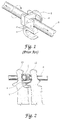
- a spinal hook such as hook H shown in FIG. 1
- the eyebolt E is threaded onto the spinal rod and captured within yokes on the spinal hook.
- a nut is threaded onto the threaded post of the eyebolt to clamp the yoke between the nut and the fixation rod R.
- the eyebolt E and hook yokes provide three degrees of fixation as represented by the arrows in FIG. 1. Details of the TSRHTM spinal implant system are disclosed in the "TSRHTM Surgical Technique Manual" provided by Danek Medical, Inc. published in 1990 which disclosure is incorporated herein by reference.
- pin holes P are situated in each of the four posts of the double-yoke hook.
- the pin holes P are designed so that they receive the pins of a hook holder.
- Such hook-holding instruments incorporate four or eight pins to correspond to the number of pinholes in the hook (which in the case of the hook H in FIG. 1 is 8 pinholes). Engagement of the pins to the pinholes is often difficult as all the components must be aligned perfectly for the instrument to be locked into place.
- the placement of the spinal hook H and engagement of the hook to the rod R by way of the eyebolt assembly E must frequently occur in very tight quarters.
- the hook is oriented between the L2 and L3 lumbar vertebra so that the hook engages the lamina L of the L2 vertebra. It can certainly be appreciated that in smaller patients, such as pediatric patients, the room to manipulate the spinal hook to engage it to the rod is very limited.
- a new spinal hook is offered by the present invention which has a smaller profile and which includes means for more easily engaging a hook holder instrument for implanting the hook.
- a spinal fixation device for interengaging a fixation rod with the human spine, comprising:
- the spinal fixation device of the present invention is more readily adaptable to various spinal anatomies without requiring that the spinal rod be bent in the saggital plane in order to contact the spinal fixation device.
- a slot is formed in the end faces of the hook.
- the slot forms one part of a tongue and slot instrument engagement arrangement, with the hook-holding instrument including a correspondingly configured tongue.
- the tongue of the hook-holder instrument engages within the slot on each central post of the hook to provide a more substantial engagement as the hook is being implanted.
- a spinal fixation assembly for interengaging a fixation rod with the human spine comprising:
- FIG. 1 illustrates a spinal hook H of a known standard design which is used as part of a spinal fixation system, such as the TSRHTM system of Danek Medical, Inc.
- the hook is fixed to a spinal rod R by way of an eyebolt assembly E.
- the hook H also includes a number of pinholes for engaging a conventional hook holder, such as the hook holder part number 808-036 of Danek Medical, Inc.
- the hook H depicted in FIG. 1 can be a hook such as the laminar hook part number 808-007 of Danek Medical, Inc.
- FIG. 2 shows the same hook H and spinal rod R engaged between the lumbar vertebra L2 and L3, specifically with the hook engaging the lamina L of the L2 vertebra.
- the spinal hook of the present invention to be described herein is intended as a substitute for this known hook H.
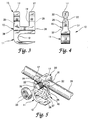
- the spinal hook 10 includes a shoe 11 having a bone-engaging surface 12.
- the bone-engaging surface 12 can be formed in a particular shape to engage a lamina of a vertebra, for instance.
- Integral with the shoe 11 of the hook 10 is a top portion 15.
- the top portion 15 includes a pair of posts 17 disposed apart from each other to form a slot 19 therebetween.
- the slot is wide enough to receive an eyebolt assembly, such as eyebolt assembly E shown in FIG. 1.
- a pair of coaxial grooves 22 are formed in each lateral surface 27 of both central posts 17.
- Each groove 22 is configured to receive a portion of a spinal rod such as rod R shown in FIG. 1.
- the rod grooves 22 are present on each lateral surface 27 of the central post 17 so that the hook 10 can be oriented on either side of a spinal rod.
- a slot 25 is formed in the outwardly facing end face 28 of each of the central posts 17.
- the slots 25 are preferably elongated and generally elliptical in shape and are cut into the post 17 to a sufficient depth for firm engagement by a hook-holding instrument, to be discussed herein.
- a spinal rod 29 is provided which extends through a rod bore 31 of an eyebolt assembly 30.
- the eyebolt assembly 30 projects through the slot 19 between the central posts 17 of the hook 10.
- the threaded post 32 of the eyebolt assembly also projects through the slot 19 for engagement with a nut 33.
- the nut 33 is then threaded onto the post 32 until it contacts a lateral surface 27 of the two central posts 17, thereby trapping the central posts between the rod 29 and the nut 33.
- the grooves 22 on the opposite lateral surfaces of the central posts 17 pinch a portion of the rod 29 to clamp the hook 10 to the rod. It should be apparent that the hook 10 could have been situated on the opposite side of the rod 29 with the rod engaged within the grooves 22 that are exposed in FIG. 5.
- a hook 40 includes a shoe 41 configured for engaging the lamina of a thoracic vertebra.
- the hook 45 of FIG. 7 includes a shoe 46 adapted to engage a transverse process
- hook 50 in FIG.8 is a pedicle hook having a shoe 51 adapted to engage a pedicle.
- the top portion of each of these hooks namely top 42 of the laminar thoracic hook, top 47 of the transverse process hook, and top 52 of the pedicle hook, are configured identically to the top portion 15 described above.
- the bone-engaging surface can be enlarged for engaging a particular vertebral component, such as shown in FIGS. 8 and 9 for the pedicle hook 50.
- the pedicle hook 50 includes a shoe 51 which is enlarged with respect to the shoes of the hooks previously described.
- a transition section 53 is provided between the central post top 52 and the shoe 51.
- a hook holder 60 which includes a pair of pivoted arms 61. Jaws 63 at the end of the arms 61 are configured for engaging the opposite end faces of a central post hook, such as hook 10 of the present invention. Specifically, the jaws include opposite inwardly facing tongues 65 which are configured to be received within the slots 25 in the end faces 28 of the central posts 17.
- the use of the tongue and slot arrangement is an improvement over the prior pin and pinhole arrangement for the hook-engaging instrument.
- the elongated area of contact between the tongues 65 and the slots 25 provides a firmer engagement between the instrument 60 and the hook 10 that is not likely to be jarred loose or require excessive manipulation during implantation of the hook during connection to a fixation rod, such as rod 29.
- the tongue and slot configuration offers greater lateral and angular strength and restraint than does the prior art pinhole and pin designs.
- the grooves 22 in the lateral faces of the central posts 17 have a diameter of 0.478cm (0.188 inches). It has been found that this groove diameter is sufficient to capture a larger rod, such as a rod having a diameter of 0.635cm (0.250 inches).
- the slots 25 for engaging the hook-holder instrument have a length of 0.792cm (0.312 inches), a width of 0.17cm (0.067 inches), and a depth of 0.104cm (0.041 inches).
- the tongues 65 of the hook-holding instrument 60 must be similarly configured but having a length, width and height slightly smaller than the corresponding dimensions of the slot 25 to allow a sliding insertion.
- the width of each central post 17 is approximately 0.478cm (0.188 inches).
- Each of the edges of the central posts 17 is rounded to avoid trauma to soft tissue surrounding the vertebra to which the hook is engaged.
- the central post hook 10 of the present invention can be easily configured to engage a variety of vertebral portions.
- the range of available hook designs for the central post hook 10 of the present invention is the same as for the prior known four-post hook designs.
- the central post hook 10 of the present invention has the flexibility of the prior hook designs coupled with the additional flexibility of situating the hook on either side of the spinal rod depending on the requirements of the specific spinal anatomy.
- the central post configuration offers a significantly reduced profile which reduces the risk of trauma to the patients, and which facilitates the implantation of the hooks 10, 40, 45 and 50 of the present invention.
Applications Claiming Priority (3)
| Application Number | Priority Date | Filing Date | Title |
|---|---|---|---|
| US815492 | 1991-12-31 | ||
| US07/815,492 US5246442A (en) | 1991-12-31 | 1991-12-31 | Spinal hook |
| PCT/US1992/010658 WO1993012737A1 (en) | 1991-12-31 | 1992-12-10 | Spinal hook |
Publications (3)
| Publication Number | Publication Date |
|---|---|
| EP0619725A1 EP0619725A1 (en) | 1994-10-19 |
| EP0619725A4 EP0619725A4 (en) | 1995-04-26 |
| EP0619725B1 true EP0619725B1 (en) | 1999-01-27 |
Family
ID=25217962
Family Applications (1)
| Application Number | Title | Priority Date | Filing Date |
|---|---|---|---|
| EP93901381A Expired - Lifetime EP0619725B1 (en) | 1991-12-31 | 1992-12-10 | Spinal hook |
Country Status (17)
| Country | Link |
|---|---|
| US (1) | US5246442A (zh) |
| EP (1) | EP0619725B1 (zh) |
| JP (1) | JP2566375B2 (zh) |
| KR (1) | KR970009552B1 (zh) |
| CN (1) | CN1076606A (zh) |
| AT (1) | ATE176146T1 (zh) |
| AU (1) | AU668535B2 (zh) |
| BR (1) | BR9207001A (zh) |
| CA (1) | CA2127130A1 (zh) |
| DE (1) | DE69228319T2 (zh) |
| ES (1) | ES2128415T3 (zh) |
| FI (1) | FI943112A0 (zh) |
| HK (1) | HK1005685A1 (zh) |
| NO (1) | NO942453D0 (zh) |
| NZ (1) | NZ246429A (zh) |
| TW (1) | TW239070B (zh) |
| WO (1) | WO1993012737A1 (zh) |
Families Citing this family (99)
| Publication number | Priority date | Publication date | Assignee | Title |
|---|---|---|---|---|
| US5527314A (en) * | 1993-01-04 | 1996-06-18 | Danek Medical, Inc. | Spinal fixation system |
| US5423818A (en) * | 1993-02-17 | 1995-06-13 | Danek Medical, Inc. | Clamp for attaching a vertebral fixation element to a spinal rod |
| US5437669A (en) * | 1993-08-12 | 1995-08-01 | Amei Technologies Inc. | Spinal fixation systems with bifurcated connectors |
| US5437670A (en) * | 1993-08-19 | 1995-08-01 | Danek Medical, Inc. | Attachment plate for top-tightening clamp assembly in a spinal fixation system |
| AU692343B2 (en) * | 1994-11-16 | 1998-06-04 | Asfs Acquisition Corp. | Segmental lamina grapple hooks |
| US5562661A (en) * | 1995-03-16 | 1996-10-08 | Alphatec Manufacturing Incorporated | Top tightening bone fixation apparatus |
| US5688272A (en) * | 1995-03-30 | 1997-11-18 | Danek Medical, Inc. | Top-tightening transverse connector for a spinal fixation system |
| US5545167A (en) * | 1995-04-11 | 1996-08-13 | Lin; Chih-I | Retaining mechanism of vertebral fixation rod |
| US5630816A (en) * | 1995-05-01 | 1997-05-20 | Kambin; Parviz | Double barrel spinal fixation system and method |
| US6416515B1 (en) | 1996-10-24 | 2002-07-09 | Spinal Concepts, Inc. | Spinal fixation system |
| EP0934026B1 (en) * | 1996-10-24 | 2009-07-15 | Zimmer Spine Austin, Inc | Apparatus for spinal fixation |
| US6045579A (en) * | 1997-05-01 | 2000-04-04 | Spinal Concepts, Inc. | Adjustable height fusion device |
| US5928243A (en) * | 1997-07-16 | 1999-07-27 | Spinal Concepts, Inc. | Pedicle probe and depth gage |
| US6454769B2 (en) | 1997-08-04 | 2002-09-24 | Spinal Concepts, Inc. | System and method for stabilizing the human spine with a bone plate |
| US6030389A (en) * | 1997-08-04 | 2000-02-29 | Spinal Concepts, Inc. | System and method for stabilizing the human spine with a bone plate |
| US5964769A (en) * | 1997-08-26 | 1999-10-12 | Spinal Concepts, Inc. | Surgical cable system and method |
| US6053921A (en) * | 1997-08-26 | 2000-04-25 | Spinal Concepts, Inc. | Surgical cable system and method |
| US5976135A (en) * | 1997-12-18 | 1999-11-02 | Sdgi Holdings, Inc. | Lateral connector assembly |
| US5944720A (en) * | 1998-03-25 | 1999-08-31 | Lipton; Glenn E | Posterior spinal fixation system |
| US6234705B1 (en) | 1999-04-06 | 2001-05-22 | Synthes (Usa) | Transconnector for coupling spinal rods |
| US6283967B1 (en) | 1999-12-17 | 2001-09-04 | Synthes (U.S.A.) | Transconnector for coupling spinal rods |
| US6413258B1 (en) * | 1999-08-12 | 2002-07-02 | Osteotech, Inc. | Rod-to-rod coupler |
| TW411838U (en) * | 1999-12-10 | 2000-11-11 | Ye Jung Chiuan | Fastening hook for spine and reposition device for fastening spine |
| US6331179B1 (en) * | 2000-01-06 | 2001-12-18 | Spinal Concepts, Inc. | System and method for stabilizing the human spine with a bone plate |
| ES2328108T3 (es) | 2000-07-28 | 2009-11-10 | Synthes Gmbh | Sistema de fijacion vertebral. |
| US7485132B1 (en) * | 2000-10-06 | 2009-02-03 | Abbott Spine Inc. | Transverse connector with cam activated engagers |
| US6887241B1 (en) | 2000-10-06 | 2005-05-03 | Spinal Concepts, Inc. | Adjustable transverse connector with cam activated engagers |
| US6872208B1 (en) | 2000-10-06 | 2005-03-29 | Spinal Concepts, Inc. | Adjustable transverse connector |
| DE10055888C1 (de) | 2000-11-10 | 2002-04-25 | Biedermann Motech Gmbh | Knochenschraube |
| US6488681B2 (en) | 2001-01-05 | 2002-12-03 | Stryker Spine S.A. | Pedicle screw assembly |
| US6770075B2 (en) | 2001-05-17 | 2004-08-03 | Robert S. Howland | Spinal fixation apparatus with enhanced axial support and methods for use |
| US6974460B2 (en) | 2001-09-14 | 2005-12-13 | Stryker Spine | Biased angulation bone fixation assembly |
| US7766947B2 (en) | 2001-10-31 | 2010-08-03 | Ortho Development Corporation | Cervical plate for stabilizing the human spine |
| JP4339698B2 (ja) * | 2002-03-11 | 2009-10-07 | ジンマー・スパイン・オースチン・インコーポレイテツド | 脊柱インプラント装置をインプラントするための器具および方法 |
| CN100420425C (zh) * | 2002-12-24 | 2008-09-24 | 叶中权 | 脊椎固定复位器 |
| FR2856270B1 (fr) * | 2003-06-17 | 2006-02-10 | Eurosurgical | Crochets pediculaires pour dispositif d'encrage rachidien. |
| AU2004257643A1 (en) * | 2003-07-03 | 2005-01-27 | Synthes Gmbh | Top loading spinal fixation device and instruments for loading and handling the same |
| US20050203513A1 (en) * | 2003-09-24 | 2005-09-15 | Tae-Ahn Jahng | Spinal stabilization device |
| US7763052B2 (en) | 2003-12-05 | 2010-07-27 | N Spine, Inc. | Method and apparatus for flexible fixation of a spine |
| US20050065516A1 (en) * | 2003-09-24 | 2005-03-24 | Tae-Ahn Jahng | Method and apparatus for flexible fixation of a spine |
| US7815665B2 (en) | 2003-09-24 | 2010-10-19 | N Spine, Inc. | Adjustable spinal stabilization system |
| US8979900B2 (en) | 2003-09-24 | 2015-03-17 | DePuy Synthes Products, LLC | Spinal stabilization device |
| US7708764B2 (en) | 2003-11-10 | 2010-05-04 | Simonson Peter M | Method for creating an artificial facet |
| US20050101953A1 (en) * | 2003-11-10 | 2005-05-12 | Simonson Peter M. | Artificial facet joint and method |
| US7083622B2 (en) * | 2003-11-10 | 2006-08-01 | Simonson Peter M | Artificial facet joint and method |
| JP2007516811A (ja) * | 2003-12-30 | 2007-06-28 | デピュイ・スパイン・エスエイアールエル | 骨アンカーアセンブリ、および、骨アンカーアセンブリの製造方法 |
| EP1699371A4 (en) * | 2003-12-30 | 2008-09-24 | Depuy Spine Sarl | BONE ANCHOR ARRANGEMENTS |
| US7678137B2 (en) * | 2004-01-13 | 2010-03-16 | Life Spine, Inc. | Pedicle screw constructs for spine fixation systems |
| US8900270B2 (en) * | 2004-02-17 | 2014-12-02 | Gmedelaware 2 Llc | Facet joint replacement instruments and methods |
| US7892257B2 (en) * | 2004-02-27 | 2011-02-22 | Custom Spine, Inc. | Spring loaded, load sharing polyaxial pedicle screw assembly and method |
| US7819902B2 (en) * | 2004-02-27 | 2010-10-26 | Custom Spine, Inc. | Medialised rod pedicle screw assembly |
| US7862594B2 (en) * | 2004-02-27 | 2011-01-04 | Custom Spine, Inc. | Polyaxial pedicle screw assembly |
| US7163539B2 (en) * | 2004-02-27 | 2007-01-16 | Custom Spine, Inc. | Biased angle polyaxial pedicle screw assembly |
| US7491207B2 (en) * | 2004-04-12 | 2009-02-17 | Synthes Usa, Llc | Rod persuader |
| US7789899B2 (en) * | 2004-12-30 | 2010-09-07 | Warsaw Orthopedic, Inc. | Bone anchorage screw with built-in hinged plate |
| US7618418B2 (en) * | 2004-04-16 | 2009-11-17 | Kyphon Sarl | Plate system for minimally invasive support of the spine |
| US7811311B2 (en) * | 2004-12-30 | 2010-10-12 | Warsaw Orthopedic, Inc. | Screw with deployable interlaced dual rods |
| US7524323B2 (en) * | 2004-04-16 | 2009-04-28 | Kyphon Sarl | Subcutaneous support |
| US7648520B2 (en) * | 2004-04-16 | 2010-01-19 | Kyphon Sarl | Pedicle screw assembly |
| US7371239B2 (en) * | 2004-07-06 | 2008-05-13 | Synthes (U.S.A.) | Spinal rod insertion instrument |
| WO2006058221A2 (en) | 2004-11-24 | 2006-06-01 | Abdou Samy M | Devices and methods for inter-vertebral orthopedic device placement |
| US7811310B2 (en) * | 2005-05-04 | 2010-10-12 | Spinefrontier, Inc | Multistage spinal fixation locking mechanism |
| US8075597B2 (en) * | 2005-09-23 | 2011-12-13 | Applied Orthopaedics Llc | Apparatus for retaining vertebrae |
| US8034078B2 (en) | 2008-05-30 | 2011-10-11 | Globus Medical, Inc. | System and method for replacement of spinal motion segment |
| US7678114B2 (en) | 2005-12-20 | 2010-03-16 | Warsaw Orthopedic, Inc. | Vertebral implant inserter and method of use |
| US20070161990A1 (en) * | 2005-12-21 | 2007-07-12 | Zimmer Spine, Inc. | Spinal implant hooks and systems |
| WO2007114834A1 (en) * | 2006-04-05 | 2007-10-11 | Dong Myung Jeon | Multi-axial, double locking bone screw assembly |
| US8388660B1 (en) | 2006-08-01 | 2013-03-05 | Samy Abdou | Devices and methods for superior fixation of orthopedic devices onto the vertebral column |
| US20080183180A1 (en) * | 2007-01-31 | 2008-07-31 | Warsaw Orthopedic, Inc. | Implant Holder and Pusher |
| EP2142121B1 (en) | 2007-04-30 | 2014-04-16 | Globus Medical, Inc. | Flexible spine stabilization system |
| US8480715B2 (en) | 2007-05-22 | 2013-07-09 | Zimmer Spine, Inc. | Spinal implant system and method |
| US20090069849A1 (en) * | 2007-09-10 | 2009-03-12 | Oh Younghoon | Dynamic screw system |
| WO2009086397A2 (en) | 2007-12-28 | 2009-07-09 | Osteomed Spine, Inc. | Bone tissue fixation device and method |
| WO2009086402A1 (en) * | 2007-12-28 | 2009-07-09 | Pronto Products, Llc | Rib bone tissue clamp |
| US8313512B2 (en) * | 2008-03-26 | 2012-11-20 | Depuy Spine, Inc. | S-shaped interspinous process spacer having tight access offset hooks |
| US8025678B2 (en) * | 2008-03-26 | 2011-09-27 | Depuy Spine, Inc. | Interspinous process spacer having tight access offset hooks |
| BRPI0919600A2 (pt) | 2008-12-17 | 2015-12-08 | Synthes Gmbh | estabilizador espinhal posterior e dinâmico |
| EP2445428A2 (en) | 2009-06-23 | 2012-05-02 | Osteomed Spine, Inc. | Bone tissue clamp |
| JP5701880B2 (ja) | 2009-08-10 | 2015-04-15 | オステオメド リミテッド ライアビリティ カンパニー | 棘突起固定移植片 |
| US8764806B2 (en) | 2009-12-07 | 2014-07-01 | Samy Abdou | Devices and methods for minimally invasive spinal stabilization and instrumentation |
| EP2471476A1 (en) * | 2010-11-10 | 2012-07-04 | Zimmer Spine | Bone anchor |
| WO2012145700A1 (en) | 2011-04-21 | 2012-10-26 | Osteomed Llc. | Bone plates, screws, and instruments |
| US8845728B1 (en) | 2011-09-23 | 2014-09-30 | Samy Abdou | Spinal fixation devices and methods of use |
| US20130226240A1 (en) | 2012-02-22 | 2013-08-29 | Samy Abdou | Spinous process fixation devices and methods of use |
| US9198767B2 (en) | 2012-08-28 | 2015-12-01 | Samy Abdou | Devices and methods for spinal stabilization and instrumentation |
| US9320617B2 (en) | 2012-10-22 | 2016-04-26 | Cogent Spine, LLC | Devices and methods for spinal stabilization and instrumentation |
| US10857003B1 (en) | 2015-10-14 | 2020-12-08 | Samy Abdou | Devices and methods for vertebral stabilization |
| WO2017156382A1 (en) | 2016-03-10 | 2017-09-14 | Nuvasive, Inc. | Bone anchor with deployable purchase element |
| KR101715387B1 (ko) * | 2016-03-25 | 2017-03-22 | 충남대학교 산학협력단 | 미세섬유 제작용 휴대장치 |
| US10575876B2 (en) | 2016-04-20 | 2020-03-03 | K2M, Inc. | Spinal stabilization assemblies with bone hooks |
| US10973648B1 (en) | 2016-10-25 | 2021-04-13 | Samy Abdou | Devices and methods for vertebral bone realignment |
| US10744000B1 (en) | 2016-10-25 | 2020-08-18 | Samy Abdou | Devices and methods for vertebral bone realignment |
| US11540863B2 (en) | 2018-07-31 | 2023-01-03 | GetSet Surgical SA | Spinal surgery systems and methods |
| US11179248B2 (en) | 2018-10-02 | 2021-11-23 | Samy Abdou | Devices and methods for spinal implantation |
| US10869696B2 (en) | 2019-01-30 | 2020-12-22 | Medos International Sarl | Surgical device for spinal fixation |
| USD926978S1 (en) | 2019-06-07 | 2021-08-03 | GetSet Surgical SA | Surgical instrument handle |
| USD927687S1 (en) | 2019-06-07 | 2021-08-10 | GetSet Surgical SA | Surgical instrument handle |
| USD896384S1 (en) | 2019-06-07 | 2020-09-15 | GetSet Surgical SA | Spinal fusion cage |
| USD926312S1 (en) | 2019-06-07 | 2021-07-27 | GetSet Surgical SA | Surgical instrument handle |
Family Cites Families (5)
| Publication number | Priority date | Publication date | Assignee | Title |
|---|---|---|---|---|
| US4567884A (en) * | 1982-12-01 | 1986-02-04 | Edwards Charles C | Spinal hook |
| FR2545350B1 (fr) * | 1983-05-04 | 1985-08-23 | Cotrel Yves | Dispositif pour l'etaiement du rachis |
| US4648388B1 (en) * | 1985-11-01 | 1995-10-31 | Acromed Corp | Apparatus and method for maintaining vertebrae in a desired relationship |
| US5007909A (en) * | 1986-11-05 | 1991-04-16 | Chaim Rogozinski | Apparatus for internally fixing the spine |
| US5002542A (en) * | 1989-10-30 | 1991-03-26 | Synthes U.S.A. | Pedicle screw clamp |
-
1991
- 1991-12-31 US US07/815,492 patent/US5246442A/en not_active Expired - Lifetime
-
1992
- 1992-12-10 AT AT93901381T patent/ATE176146T1/de not_active IP Right Cessation
- 1992-12-10 CA CA002127130A patent/CA2127130A1/en not_active Abandoned
- 1992-12-10 EP EP93901381A patent/EP0619725B1/en not_active Expired - Lifetime
- 1992-12-10 WO PCT/US1992/010658 patent/WO1993012737A1/en active IP Right Grant
- 1992-12-10 DE DE69228319T patent/DE69228319T2/de not_active Expired - Fee Related
- 1992-12-10 AU AU32750/93A patent/AU668535B2/en not_active Ceased
- 1992-12-10 KR KR1019940700356A patent/KR970009552B1/ko not_active IP Right Cessation
- 1992-12-10 JP JP5511694A patent/JP2566375B2/ja not_active Expired - Fee Related
- 1992-12-10 ES ES93901381T patent/ES2128415T3/es not_active Expired - Lifetime
- 1992-12-10 NZ NZ246429A patent/NZ246429A/en unknown
- 1992-12-10 BR BR9207001A patent/BR9207001A/pt active Search and Examination
- 1992-12-31 CN CN92115330.9A patent/CN1076606A/zh active Pending
-
1993
- 1993-01-13 TW TW082100170A patent/TW239070B/zh active
-
1994
- 1994-06-29 NO NO942453A patent/NO942453D0/no unknown
- 1994-06-29 FI FI943112A patent/FI943112A0/fi not_active Application Discontinuation
-
1998
- 1998-06-03 HK HK98104821A patent/HK1005685A1/xx not_active IP Right Cessation
Also Published As
| Publication number | Publication date |
|---|---|
| ATE176146T1 (de) | 1999-02-15 |
| HK1005685A1 (en) | 1999-01-22 |
| DE69228319D1 (de) | 1999-03-11 |
| NO942453L (no) | 1994-06-29 |
| BR9207001A (pt) | 1995-12-05 |
| AU668535B2 (en) | 1996-05-09 |
| AU3275093A (en) | 1993-07-28 |
| TW239070B (zh) | 1995-01-21 |
| ES2128415T3 (es) | 1999-05-16 |
| FI943112A (fi) | 1994-06-29 |
| EP0619725A4 (en) | 1995-04-26 |
| KR970009552B1 (ko) | 1997-06-14 |
| DE69228319T2 (de) | 1999-07-15 |
| EP0619725A1 (en) | 1994-10-19 |
| NZ246429A (en) | 1998-04-27 |
| NO942453D0 (no) | 1994-06-29 |
| JP2566375B2 (ja) | 1996-12-25 |
| CA2127130A1 (en) | 1993-07-08 |
| FI943112A0 (fi) | 1994-06-29 |
| WO1993012737A1 (en) | 1993-07-08 |
| CN1076606A (zh) | 1993-09-29 |
| US5246442A (en) | 1993-09-21 |
| JPH06510466A (ja) | 1994-11-24 |
Similar Documents
| Publication | Publication Date | Title |
|---|---|---|
| EP0619725B1 (en) | Spinal hook | |
| AU2008316641B2 (en) | Surgical fixation system and related methods | |
| US7066938B2 (en) | Snap-on spinal rod connector | |
| US5609592A (en) | Spinal Fixation System | |
| US8728080B2 (en) | Spinal fixation plates and plate extensions | |
| US5947966A (en) | Device for linking adjacent rods in spinal instrumentation | |
| AU2006235095B2 (en) | Systems, devices and methods for stabilization of the spinal column | |
| US8961572B2 (en) | Dual rod cross connectors and inserter tools | |
| US7794478B2 (en) | Polyaxial cross connector and methods of use thereof | |
| EP2010082B1 (en) | Connector apparatus | |
| US20060064091A1 (en) | Rod attachment for head to head cross connector | |
| US11103283B2 (en) | Integral double rod spinal construct | |
| JPH0998984A (ja) | 頸部脊柱のゆ合のための骨接合用装置 | |
| US11944357B2 (en) | Minimally invasive surgery add on screw system | |
| KR20190001708A (ko) | 타원형의 머리부를 갖는 척추 고정용 임플란트 | |
| HU219431B (hu) | Csontrögzítő implantátum |
Legal Events
| Date | Code | Title | Description |
|---|---|---|---|
| PUAI | Public reference made under article 153(3) epc to a published international application that has entered the european phase |
Free format text: ORIGINAL CODE: 0009012 |
|
| 17P | Request for examination filed |
Effective date: 19940701 |
|
| AK | Designated contracting states |
Kind code of ref document: A1 Designated state(s): AT BE CH DE DK ES FR GB GR IE IT LI LU MC NL PT SE |
|
| A4 | Supplementary search report drawn up and despatched |
Effective date: 19950315 |
|
| AK | Designated contracting states |
Kind code of ref document: A4 Designated state(s): AT BE CH DE DK ES FR GB GR IE IT LI LU MC NL PT SE |
|
| 17Q | First examination report despatched |
Effective date: 19970404 |
|
| GRAG | Despatch of communication of intention to grant |
Free format text: ORIGINAL CODE: EPIDOS AGRA |
|
| GRAG | Despatch of communication of intention to grant |
Free format text: ORIGINAL CODE: EPIDOS AGRA |
|
| GRAH | Despatch of communication of intention to grant a patent |
Free format text: ORIGINAL CODE: EPIDOS IGRA |
|
| GRAH | Despatch of communication of intention to grant a patent |
Free format text: ORIGINAL CODE: EPIDOS IGRA |
|
| GRAA | (expected) grant |
Free format text: ORIGINAL CODE: 0009210 |
|
| AK | Designated contracting states |
Kind code of ref document: B1 Designated state(s): AT BE CH DE DK ES FR GB GR IE IT LI LU MC NL PT SE |
|
| PG25 | Lapsed in a contracting state [announced via postgrant information from national office to epo] |
Ref country code: SE Free format text: THE PATENT HAS BEEN ANNULLED BY A DECISION OF A NATIONAL AUTHORITY Effective date: 19990127 Ref country code: NL Free format text: LAPSE BECAUSE OF FAILURE TO SUBMIT A TRANSLATION OF THE DESCRIPTION OR TO PAY THE FEE WITHIN THE PRESCRIBED TIME-LIMIT Effective date: 19990127 Ref country code: LI Free format text: LAPSE BECAUSE OF FAILURE TO SUBMIT A TRANSLATION OF THE DESCRIPTION OR TO PAY THE FEE WITHIN THE PRESCRIBED TIME-LIMIT Effective date: 19990127 Ref country code: IT Free format text: LAPSE BECAUSE OF FAILURE TO SUBMIT A TRANSLATION OF THE DESCRIPTION OR TO PAY THE FEE WITHIN THE PRESCRIBED TIME-LIMIT;WARNING: LAPSES OF ITALIAN PATENTS WITH EFFECTIVE DATE BEFORE 2007 MAY HAVE OCCURRED AT ANY TIME BEFORE 2007. THE CORRECT EFFECTIVE DATE MAY BE DIFFERENT FROM THE ONE RECORDED. Effective date: 19990127 Ref country code: GR Free format text: LAPSE BECAUSE OF NON-PAYMENT OF DUE FEES Effective date: 19990127 Ref country code: CH Free format text: LAPSE BECAUSE OF FAILURE TO SUBMIT A TRANSLATION OF THE DESCRIPTION OR TO PAY THE FEE WITHIN THE PRESCRIBED TIME-LIMIT Effective date: 19990127 Ref country code: BE Free format text: LAPSE BECAUSE OF FAILURE TO SUBMIT A TRANSLATION OF THE DESCRIPTION OR TO PAY THE FEE WITHIN THE PRESCRIBED TIME-LIMIT Effective date: 19990127 Ref country code: AT Free format text: LAPSE BECAUSE OF FAILURE TO SUBMIT A TRANSLATION OF THE DESCRIPTION OR TO PAY THE FEE WITHIN THE PRESCRIBED TIME-LIMIT Effective date: 19990127 |
|
| REF | Corresponds to: |
Ref document number: 176146 Country of ref document: AT Date of ref document: 19990215 Kind code of ref document: T |
|
| REG | Reference to a national code |
Ref country code: CH Ref legal event code: EP |
|
| ET | Fr: translation filed | ||
| REG | Reference to a national code |
Ref country code: IE Ref legal event code: FG4D |
|
| REF | Corresponds to: |
Ref document number: 69228319 Country of ref document: DE Date of ref document: 19990311 |
|
| PG25 | Lapsed in a contracting state [announced via postgrant information from national office to epo] |
Ref country code: PT Free format text: LAPSE BECAUSE OF FAILURE TO SUBMIT A TRANSLATION OF THE DESCRIPTION OR TO PAY THE FEE WITHIN THE PRESCRIBED TIME-LIMIT Effective date: 19990427 Ref country code: DK Free format text: LAPSE BECAUSE OF FAILURE TO SUBMIT A TRANSLATION OF THE DESCRIPTION OR TO PAY THE FEE WITHIN THE PRESCRIBED TIME-LIMIT Effective date: 19990427 |
|
| REG | Reference to a national code |
Ref country code: ES Ref legal event code: FG2A Ref document number: 2128415 Country of ref document: ES Kind code of ref document: T3 |
|
| NLV1 | Nl: lapsed or annulled due to failure to fulfill the requirements of art. 29p and 29m of the patents act | ||
| REG | Reference to a national code |
Ref country code: CH Ref legal event code: PL |
|
| PLBE | No opposition filed within time limit |
Free format text: ORIGINAL CODE: 0009261 |
|
| STAA | Information on the status of an ep patent application or granted ep patent |
Free format text: STATUS: NO OPPOSITION FILED WITHIN TIME LIMIT |
|
| PG25 | Lapsed in a contracting state [announced via postgrant information from national office to epo] |
Ref country code: LU Free format text: LAPSE BECAUSE OF NON-PAYMENT OF DUE FEES Effective date: 19991210 Ref country code: IE Free format text: LAPSE BECAUSE OF NON-PAYMENT OF DUE FEES Effective date: 19991210 |
|
| 26N | No opposition filed | ||
| PG25 | Lapsed in a contracting state [announced via postgrant information from national office to epo] |
Ref country code: MC Free format text: LAPSE BECAUSE OF NON-PAYMENT OF DUE FEES Effective date: 20000630 |
|
| REG | Reference to a national code |
Ref country code: IE Ref legal event code: MM4A |
|
| REG | Reference to a national code |
Ref country code: GB Ref legal event code: IF02 |
|
| PGFP | Annual fee paid to national office [announced via postgrant information from national office to epo] |
Ref country code: ES Payment date: 20071211 Year of fee payment: 16 |
|
| PGFP | Annual fee paid to national office [announced via postgrant information from national office to epo] |
Ref country code: GB Payment date: 20071106 Year of fee payment: 16 |
|
| PGFP | Annual fee paid to national office [announced via postgrant information from national office to epo] |
Ref country code: DE Payment date: 20071228 Year of fee payment: 16 |
|
| PGFP | Annual fee paid to national office [announced via postgrant information from national office to epo] |
Ref country code: FR Payment date: 20071204 Year of fee payment: 16 |
|
| GBPC | Gb: european patent ceased through non-payment of renewal fee |
Effective date: 20081210 |
|
| REG | Reference to a national code |
Ref country code: FR Ref legal event code: ST Effective date: 20090831 |
|
| PG25 | Lapsed in a contracting state [announced via postgrant information from national office to epo] |
Ref country code: DE Free format text: LAPSE BECAUSE OF NON-PAYMENT OF DUE FEES Effective date: 20090701 |
|
| PG25 | Lapsed in a contracting state [announced via postgrant information from national office to epo] |
Ref country code: GB Free format text: LAPSE BECAUSE OF NON-PAYMENT OF DUE FEES Effective date: 20081210 |
|
| REG | Reference to a national code |
Ref country code: ES Ref legal event code: FD2A Effective date: 20081211 |
|
| PG25 | Lapsed in a contracting state [announced via postgrant information from national office to epo] |
Ref country code: FR Free format text: LAPSE BECAUSE OF NON-PAYMENT OF DUE FEES Effective date: 20081231 Ref country code: ES Free format text: LAPSE BECAUSE OF NON-PAYMENT OF DUE FEES Effective date: 20081211 |