EP0617338A2 - Carrier for use in electrophotography and two component-type developer containing the carrier - Google Patents
Carrier for use in electrophotography and two component-type developer containing the carrier Download PDFInfo
- Publication number
- EP0617338A2 EP0617338A2 EP94104701A EP94104701A EP0617338A2 EP 0617338 A2 EP0617338 A2 EP 0617338A2 EP 94104701 A EP94104701 A EP 94104701A EP 94104701 A EP94104701 A EP 94104701A EP 0617338 A2 EP0617338 A2 EP 0617338A2
- Authority
- EP
- European Patent Office
- Prior art keywords
- carrier
- carrier according
- resin
- toner
- formula
- Prior art date
- Legal status (The legal status is an assumption and is not a legal conclusion. Google has not performed a legal analysis and makes no representation as to the accuracy of the status listed.)
- Granted
Links
Images

Classifications
-
- G—PHYSICS
- G03—PHOTOGRAPHY; CINEMATOGRAPHY; ANALOGOUS TECHNIQUES USING WAVES OTHER THAN OPTICAL WAVES; ELECTROGRAPHY; HOLOGRAPHY
- G03G—ELECTROGRAPHY; ELECTROPHOTOGRAPHY; MAGNETOGRAPHY
- G03G9/00—Developers
- G03G9/08—Developers with toner particles
- G03G9/10—Developers with toner particles characterised by carrier particles
- G03G9/113—Developers with toner particles characterised by carrier particles having coatings applied thereto
- G03G9/1132—Macromolecular components of coatings
- G03G9/1135—Macromolecular components of coatings obtained otherwise than by reactions only involving carbon-to-carbon unsaturated bonds
- G03G9/1136—Macromolecular components of coatings obtained otherwise than by reactions only involving carbon-to-carbon unsaturated bonds containing silicon atoms
Definitions
- the present invention relates to a carrier for use in electrophotography, and a two component-type developer containing the carrier and a toner for developing electrostatic images.
- toner particles charged to a polarity opposite to that of the latent image is attracted by electrostatic force to be caused to attach onto the latent image.
- toner particles having a triboelectric charge of the same polarity as that of the latent image is used.
- methods for developing an electrostatic latent image with a toner can be classified into a developing method using a two component-type developer constituted by mixing a small amount of a toner with carrier and a developing method using a monocomponent-type developer constituted by a toner alone without containing a carrier.
- the carrier constituting the two component-type developer may generally be classified roughly into an electroconductive carrier and an insulating carrier.
- the electroconductive carrier may generally comprise oxidized or yet-unoxidized iron powder.
- the two component-type developer comprising iron powder carrier is accompanied with problems that the triboelectric chargeability of the toner is liable to be unstable and the resultant visible image formed by the developer is liable to be accompanied with fog. Further, along with continual use of the developer, toner particles adhere onto the surface of the iron powder carrier particles to increase the electrical resistivity of the carrier particles, so that the bias current decreases and the triboelectric charge is instabilized. As a result, the resultant toner image is liable to have a lower image density and be accompanied with increased fog.
- the insulating carrier representatively comprises a core material of a ferromagnetic material, such as iron, nickel or ferrite, uniformly coated with an insulating resin.
- the developer using this type of carrier is advantageous in that the adhesion of toner particles onto the carrier surface is remarkably less than in the case of the electroconductivity, and the developer is excellent in durability and has a long service life, so that the developer is particularly suitable for a high-speed electrophotographic copying machine.
- Such an insulating carrier is required to satisfy several requirements inclusive of: a durability that the coating layer covering the carrier core shows a sufficient wear resistance and a strong adhesion onto the core, an anti-soiling characteristic that the coating layer shows a good sticking prevention effect so as to prevent filming of the toner material on the carrier surface and a charging characteristic that a specific toner used in combination with the carrier is provided with a triboelectric charge of a desired polarity through friction with the carrier.
- the carrier particles are subjected to friction with the other carrier particles and toner particles within a developing device and, if the carrier coating surface is covered with a film of the attached toner, the charging characteristic becomes unstable.
- a carrier coated with a fluorine-containing resin such as a tetrafluoroethylene copolymer has a low critical surface tension so that the toner soiling does not readily occur, but is poor in film forming characteristic so that it becomes difficult to sufficiently uniformly coat the carrier core and it is difficult to obtain a stable charging characteristic.
- the fluorine-containing resin also shows a poor adhesion with the core material and is liable to provide an insufficient wear resistance. Further, because of its position in the triboelectrification series, a fluorine-containing resin-coated carrier cannot provide a sufficient negative charge to a toner.
- a carrier coated with an acrylic resin such as a styrene-methacrylate copolymer
- an acrylic resin shows a relatively high critical surface tension and is liable to suffer from soiling with toner on repetitive use, thus leaving some problem in respect of the life of the developer. Further, the wear resistance thereof is not sufficiently high while its surface hardness is relatively high.
- a silicone resin has a low surface energy and can decrease the soiling with toner, but shows a rather low mechanical strength so that the coating layer composed thereof is liable to be worn out while being stirred within the developing device. Thus, it is difficult to provide a stable charging characteristic. It is possible to use a polymer having a polydialkylsiloxane structure unit in mixture with another polymer, such as a styrene-acrylate copolymer. In this case, however, the polydialkylsiloxane-containing polymer is condensed at the surface and is liable to be preferentially lost during stirring within the developing device, so that it becomes difficult to stabilize the charging characteristic over a long period.
- a carrier for a two-component type developer capable of showing a satisfactory charging characteristic, excellent soiling resistance and good successive copying characteristic on a large number of sheets and also capable of providing high-quality toner images.
- a two-component type developer comprising a toner and a magnetic carrier is applied in a prescribed coating layer thickness by a developer layer thickness-regulating member on a developing sleeve enclosing a magnet inside thereof and conveyed in utilization of a magnetic force to a developing zone formed between a photosensitive member and the developing sleeve.
- a prescribed developing bias voltage is applied so as to develop an electrostatic latent image with a toner in the developing zone.
- the magnetic carrier is required to show appropriate charging characteristic, withstand voltage resistant to an applied voltage, impact resistance, wear resistance, anti-spent characteristic, developing characteristic and productivity.
- the anti-spent characteristic for example, in the case of a continual use of a developer for a long period, a so-called “spent toner” (a filming or melt-sticking of a toner) is attached onto the carrier surface, thus resulting in a deterioration of the developer and thus an image quality deterioration of the developed images.
- a so-called "spent toner” a filming or melt-sticking of a toner
- a large load is applied onto the developer at the time of applying the developer in a prescribed layer thickness on the sleeve by the above-mentioned developer layer thickness-regulating means or at the time of stirring the developer within the developing device, so that (a) toner filming and (a) toner deterioration are liable to be caused during the long use of the developer, thus causing deterioration of the developer and image quality deterioration of the developed images.
- a developer containing a carrier liable to cause the above difficulties (a) and (b) requires a periodical exchange thereof or improvement of the carrier regarding the durability and anti-spent characteristic so as to alleviate the difficulties (a) and (b), thus prolonging the life of the developer.
- a carrier comprising magnetic particles dispersed within a binder resin, e.g., a magnetic material-dispersion type carrier produced by pulverization, e.g., as proposed in Japanese Laid-Open Patent Application (JP-A) 56-66134.
- JP-A Japanese Laid-Open Patent Application
- the above-mentioned magnetic material-dispersion type developers are accompanied with a difficulty that, unless a large amount of magnetic material is incorporated in a carrier particle, the carrier shows a small saturation magnetization relative to the particle size and is liable to attach to the photosensitive member at the time of developing. As a result, it is necessary to install mechanisms for replenishing the developer and recovering the attached carrier within the image forming apparatus. Thus, the magnetic material-dispersion type carrier is not sufficiently satisfactory as a measure for prolonging the life of the developer.
- the magnetic material having a low resistivity is increased in amount to be exposed to the carrier surface to lower the resistivity of the carrier, so that the resultant image quality is liable to be lowered due to leakage of the bias voltage applied during the development.
- the amount of the magnetic material is increased relative to the binder resin to make the carrier less resistant to a mechanical impact, So that the magnetic material is liable to drop off the carrier at the time of applying the developer in a prescribed layer thickness on the sleeve by the developer layer thickness-regulating means. As a result, the developer is liable to be deteriorated again.
- the fine particles resultant after the dropping or breakage of the magnetic material have a low magnetic property so that they cannot be held on the sleeve at the time of development to attach to the photosensitive member, thus generating image defects.
- binder resin for dispersing magnetic material particles to produce a magnetic material-dispersion type carrier various resins have been known and used, such as acrylic resin, vinyl resin, styrene-acrylate copolymer, styrene-butadiene copolymer, ethylene-vinyl acetate copolymer, and further, polyester resin, epoxy resin, phenolic resin, urea resin, polyurethane resin, polyimide resin, cellulosic resin, low-molecular weight polypropylene, vinyl chloride resin, vinyl acetate resin, copolymers of these resins, and petroleum resin.
- acrylic resin acrylic resin
- vinyl resin styrene-acrylate copolymer
- styrene-butadiene copolymer ethylene-vinyl acetate copolymer
- polyester resin epoxy resin, phenolic resin, urea resin, polyurethane resin, polyimide resin, cellulosic resin, low-molecular weight polypropylene,
- a resinous carrier composition utilizing a binder resin as described above in mixture with a magnetic material cause a decrease in impact resistance and wear resistance particularly when used for a long period, and is therefore liable to cause the breakage or wearing of the carrier per se, thus failing to show a sufficient charging characteristic and also resulting in fine carrier particles which adhere to the photosensitive member during development and cause fog at the non-image parts of the developed images.
- the carrier binder resin has a relatively close chemical composition to a toner binder resin (e.g., styrene-butadiene copolymer, styrene-acrylate copolymer or polyester resin)
- the toner readily adheres to the carrier to change and/or lower the triboelectric charging ability, so that it is difficult to provide a two-component type developer which provides high-quality images, and are excellent in successive image formation characteristic and highly stable.
- curable resin such as epoxy resin
- the use of a curable resin is accompanied with a problem that a foreign matter is rather accumulated on the surface to result in a remarkable change in triboelectric charging characteristic.
- a generic object of the present invention is to provide a carrier for use in electrophotography (hereinafter sometimes referred to as “electrophotographic carrier” or simply “carrier”) having solved the above-mentioned problems.
- a more specific object of the present invention is to provide an electrophotographic carrier which is excellent in wear resistance and impact resistance.
- Another object of the present invention is to provide an electrophotographic carrier which is not readily stained or soiled by the toner.
- Another object of the present invention is to provide an electrophotographic carrier coated with a highly durable resin which has sufficient mechanical strength against wearing and impact.
- Another object of the present invention is to provide a resin-coated electrophotographic carrier which is excellent in surface releasability, less susceptible to soiling with the toner and is excellent in stability.
- Another object of the present invention is to provide a magnetic material dispersion-type electrophotographic carrier less susceptible to soiling with the toner.
- Another object of the present invention is to provide a magnetic material dispersion-type electrophotographic carrier excellent in wear resistance and impact resistance.
- Another object of the present invention is to provide a magnetic material dispersion-type electrophotographic carrier which is less liable to stick to a photosensitive member.
- a further object of the present invention is to provide a two-component type developer capable of providing high-quality toner images.
- Another object of the present invention is to provide a two-component type developer excellent in successive image forming characteristic on a large number of sheets.
- a carrier for use in electrophotography comprising a magnetic material and a resin, said resin comprising a copolymer having structural units of the following formulae [1] and [2]: wherein A denotes a C i - C10 o linear, branched or cyclic alkylidene group, aryl-substituted alkylidene group or arylenedialkylidene group, -O-, -S-, -CO-, -SO- or -S0 2 -; and R i - R 4 independently denote hydrogen, halogen, or a Ci - C 4 alkyl or alkenyl group; wherein R 5 denotes a C 2 - C 6 alkylene or alkylidene group; R 6 and R 7 denote a C i - C 3 alkyl group, a phenyl group or a substituted phenyl group; and n is an integer of 1 - 200.
- a two-component type developer for developing an electrostatic image comprising a toner and the above-mentioned carrier.
- a copolymer showing an improved surface releasability without causing a lowered carrier strength is used as a carrier-forming material in order to provide a highly durable and highly stable carrier having solved the above-mentioned problems.
- the copolymer used in the present invention is characterized by having a polycarbonate unit providing a good impact resistance and a polydialkylsiloxane unit and is provided with an improved surface lubricity while retaining the impact resistance.
- the copolymer used in the present invention is characterized by having a structural unit of the formula [1 ] and a structural unit of the formula [2] described above and may preferably be in the form of a block copolymer having at least one block copolymer unit including a polycarbonate unit and a polysiloxane unit and represented by the following formula [3]: wherein Ri - R 4 and A have the same meanings as in the formula [1]; Rs - R 7 and n have the same meanings as in the formula [2]; and m is a positive integer.
- the number n in the structural unit [2] may preferably be in the range of 10 - 150.
- the block copolymer may preferably comprise 99.9 - 50 wt.
- the structural unit [1] of the copolymer may be derived, e.g., from a diol represented by the following formula: wherein R 1 - R 4 and A respectively have the same meanings as in the formula [1 ].
- the structural unit [2] of the copolymer may be derived, e.g., from a polysiloxane-diol represented by the following formula [2A]: wherein R s - R 7 have the same meanings as in the formula [2] and n may preferably be 10 - 50.
- diphenol compounds providing the polycarbonate unit (structural unit [1]) of the copolymer are enumerated below, but they are not exhaustive:
- the copolymer used in the present invention may be synthesized by polymerization using a diol and a polyorganosiloxane as described above through the phosgene process, the ester exchange process or the chloroformate intermediate process. It is suitable to apply polymerization according to the phosgene process in a solution system in order to stabilize the randomness of the copolymerization. It is possible to apply, e.g., a process disclosed in U.S. Patent No. 3,781,378 (corr. to JP-A 48-64199) in order to produce a polycarbonate block copolymer.
- the copolymer used in the present invention may preferably have a weight-average molecular weight of 10,000 - 100,000 in view of the wear resistance and durability.
- the carrier of the present invention may suitably have an average particle size (diameter) of 5 - 100 am. If the carrier particle size is below 5 ⁇ m, the carrier is liable to attach to the photosensitive member. In excess of 100 ⁇ m, a large shearing force is applied to the developer within the developing device, thus being liable to cause deterioration of the developer, particularly separation of external additive from the toner and shape change of the toner. Too large a particle size provides a smaller specific surface area, so that a smaller amount of toner is retained by the carrier, thus being liable to provide images with lower definition.
- the two-component type developer of the present invention it is preferred to select a combination of a carrier and a toner so as to provide a toner triboelectric charge of 5 - 50 ⁇ c/g in terms of an absolute value through friction between the carrier and the toner.
- the carrier surface releasability is improved so that it is possible to effectively prevent the lowering in carrier life due to the soiling with the toner.
- the coating solution can be uniformized to prevent a lowering in strength of the carrier coating layer, thus providing an improved durability.
- a developer comprising the carrier of the present invention is excellent in successive copying characteristic and stability. It is generally preferred that the copolymer has a higher glass transition point so as to provide an improved thermal stability.
- the copolymer used in the present invention can provide a clear solution when dissolved in a solvent, thus providing a sufficiently tough resin coating. This is particularly true when a dialkylsiloxane-block diphenol compound of the above formula [2A] is used for copolymerization so as to effect the copolymerization in a sufficiently random manner. This is presumably effective in preventing the growth of a long chain polydialkylsiloxane block leading to a lower solubility and a turbid solution. Further, it is also possible to prevent the formation of a polymer chain of polydialkylsiloxane alone, thus providing a copolymer showing stable properties.
- Such a coated carrier may be formed, e.g., by dissolving the copolymer in an appropriate solvent including, e.g., an aromatic solvent, such as benzene, toluene or xylene; a halogenated compound, such as dichloromethane, trichloromethane or chlorobenzene; or a cyclic ether, such as tetrahydrofuran, tetrahydropyrane or dioxane, applying the resultant solution onto the surfaces of the magnetic carrier core particles, and drying the resultant coating solution film to form a resin film on the magnetic carrier core surfaces.
- an aromatic solvent such as benzene, toluene or xylene
- a halogenated compound such as dichloromethane, trichloromethane or chlorobenzene
- a cyclic ether such as tetrahydrofuran, tetrahydropyrane or dioxane
- the polycarbonate-polysiloxane block copolymer may preferably have a weight-average molecular weight of 10,000 - 100,000. If the molecular weight is below 10,000, the durability is liable to be lowered. If the molecular weight exceeds 100,000, the coating solution is caused to have a high viscosity, so that it is difficult to form a uniform coating in a prescribed amount.
- the copolymer may be dissolved in a suitable solvent (e.g., dichloromethane) to form a carrier coating solution, and the solution maybe applied onto a magnetic ferrite carrier by means of an appropriate applicator ("Spira Cota", mfd. by Okada Seiko K.K.).
- a suitable solvent e.g., dichloromethane
- the coated product may be preliminarily dried at 70 - 80 °C to evaporate the solvent, followed by a heat treatment for 0.5 - 1 hour at 120 - 160 °C.
- the coating resin amount of the coated carrier may appropriately be selected so as to satisfy desired durability and charging characteristic, but may generally preferably be in the range of 0.01 - 30 wt. % of the carrier core. Below 0.01 wt. %, the coating effect is low.
- the resin coating amount CW (wt. %) may depend on the true specific gravity Z of the carrier core material and may preferably be within the range of 1/2Z ⁇ CW ⁇ 50/Z, more preferably in the range of 1/Z ⁇ CW 25/Z.
- the magnetic carrier core material may comprise particles of a magnetic material, such as iron or ferrite.
- an adhesion promoter examples of which may include: silane coupling agents, such as methyltrimethoxysilane, methyltriethoxysilane, vinyltriethoxysilane, vinyltris(methoxyethoxysilane), vinyltriacetoxysilane, y-methacryloxypropyltrimethoxysilane, y-aminopropyltriethoxysilane, y-(aminoethyl)-aminopropyltriethoxysilane, y-glycidoxypropyltrimethoxysilane, y-mercaptopropyltrimethoxysilane, ⁇ -(3,4-epoxycyclohexyl)ethyltrimethoxysilane, and y-chloropropyltrimethoxysilane; organic titanium compounds, such as tet
- These compounds may be used singly or in mixture of two or more species. These compounds may be applied in advance onto the carrier core, followed by coating with the copolymer of the present invention. Alternatively, it is also possible to admix such an adhesion promoter with the copolymer of the present invention, and then apply the admixture onto the carrier core at a time.
- the copolymer used in the present invention may be used in mixture with another resin within an extent of not lowering the effect of the copolymer.
- another resin may include: acrylic resin, styrene-acrylate copolymer resin, ethylene-vinyl acetate copolymer resin, polyester resin, polyethylene resin, polypropylene resin, polyvinylcarbazole resin, phenoxy resin, polycarbonate resin, polyvinyl butyral resin, polystyrene resin, polyvinyl acetate resin, polyallylate resin, and polysulfone resin.
- the coated carrier according to the present invention may preferably have a resistivity in the range of 10 8 - 10 14 ohm.cm.
- the polycarbonate-polydiorganosiloxane block copolymer can well disperse magnetic material particles and firmly bond with the magnetic material particles.
- the copolymer may suitably be used as a binder resin of the magnetic material-dispersion type carrier to solve the problems of the prior art.
- the copolymer may preferably have a weight-average molecular weight in the range of 10,000 to 50,000. If the molecular weight is below 10,000, the durability is lowered. In excess of 50,000, the melt viscosity of the copolymer at the time of melt-kneading of the copolymer with the particles of the magnetic material is liable to be excessively high, so that a satisfactory melt-kneading is liable to be difficult.
- the polycarbonate-polydiorganosiloxane block copolymer may suitably have a glass transition point below 155 °C so as to provide a good processability at the time of melt-kneading.
- the copolymer as a binder resin of the magnetic material-dispersion type carrier, it becomes possible to provide improved wear resistance and anti-toner soiling characteristic and also suppress the toner deterioration. This is presumably because the copolymer of the present invention is rich in lubricity than an ordinary binder resin, thus resulting in an improved anti-toner soiling characteristic and also a reduced shear stress applied to the toner.
- Examples of the magnetic material used in the magnetic material-dispersion type carrier may include: ferromagnetic metals, such as iron, cobalt, and nickel, and alloys of these metals, and compounds, such as magnetite and hematite, containing an element showing ferromagnetism, such as iron, cobalt and nickel.
- the magnetic material may preferably have a saturation magnetization of 10 - 100 emu/g as measured at a magnetic field of 10 kilo-oersted by means of a tester (e.g., "VSM" available from Toei Kogyo K.K.).
- the magnetic material may preferably have an average primary particle size of at most 2.0 am. If the particle size exceeds 2.0 am, the resultant carrier particles are liable to have inferior surface state and have a charging ability which is unstable due to a change in environmental condition.
- the magnetic material fine particles may preferably have a resistivity of at most 10 9 ohm.cm.
- the magnetic material may preferably be contained in a proportion of at least 30 wt. %, further preferably at least 50 wt. %, in the carrier composition. Below 30 wt. %, the resultant carrier particles are liable to attach to the photosensitive member and the control of the electrical resistivity of the carrier is liable to be difficult.
- the attachment of the magnetic material-dispersion type carrier according to the present invention onto the photosensitive member can be suppressed, and the ability of charging the carrier can be effectively controlled.
- the magnetic material-dispersion type carrier may preferably have a true specific gravity of 1.5 - 5.0, further suitably 1.5 - 4.5. If the true specific gravity exceeds 5.0, a large load is applied onto the two-component type developer within the developing device, thus being liable to deteriorate the developer. If the true specific gravity is below 1.5, it is difficult to provide a magnetic force sufficient to suppress the attachment of the carrier onto the photosensitive member.
- the true specific gravity of the carrier may be measured by using, e.g., "Truedenser" (trade mark) available from Seishin Kigyo K.K.
- the carrier of the present invention may suitably have an electrical resistivity of 10 7 - 10 15 ohm.cm, preferably 10 8 - 10 14 ohm.cm. If a carrier having a resistivity of below 10 7 ohm.cm is used in a development method applying a bias voltage, some current is liable to leak from the developing sleeve to the photosensitive member in the developing region, so that it becomes difficult to obtain good toner images. Above 10 15 ohm.cm, the charge-up phenomenon is liable to occur in a low humidity environment to result in image difficulties, such as a low density, transfer failure and fog.
- the carrier may preferably have a sphericity (long axis/short axis ratio) of at most 2. If the sphericity exceeds 2, the intended effects are liable to be diminished regarding the effect of reducing the shear stress applied to the developer and the effect of improving the fluidity of the resultant developer.
- the sphericity of below 2 may be accomplished by rounding the carrier particles by thermally melting the surfaces thereof or by a mechanical treatment.
- the carrier according to the present invention may be produced through various processes including: a process wherein the binder resin and the magnetic material fine particles are blended in an appropriate ratio and melt-kneaded at an appropriate temperature by a hot-melt kneading means such as a three-roll mill or an extruder, followed by cooling, pulverization and classification; and a process wherein the binder resin (copolymer) is dissolved in an appropriate solvent, and the magnetic material is blended therewith to form a slurry, which is then formed into particles and dried by a spray dryer. In any process, it is important to uniformly disperse the magnetic material fine particles within the carrier particles.
- the magnetic material-dispersion type carrier prepared through such a process can be further coated with a resin for the purpose of further controlling the resistivity and adjusting the surface property to some extent.
- the two-component type developer according to the present invention may be prepared by blending 10 - 1000 wt. parts, preferably 30 - 500 wt. parts, of the carrier with 10 wt. parts of a toner.
- the toner used in the present invention may suitably have a weight-average particle size of 1 - 20 am, preferably 4 - 13 am.
- the toner used in the present invention when used in combination with a hot-pressure roller fixing apparatus equipped with an oil applicator, may comprise a binder resin, examples of which may include: polystyrene; polymers of styrene derivatives, such as poly-p-chlorostyrene, and polyvinyltoluene; styrene copolymers, such as styrene-p-chlorostyrene copolymer, styrene-vinyltoluene copolymer, styrene-vinylnaphthalene copolymer, styrene-acrylate copolymer, styrene-methacrylate copolymer, styrene-methyl a-chloromethacrylate copolymer, styrene-acrylonitrile copolymer, styrene-vinyl methyl ketone copolymer, styrene-
- the toner for use in combination with a hot-pressure roller fixing apparatus using little or no oil is required to show a sufficient adhesion onto a toner image supporting member as an important characteristic.
- a toner fixable with less heat energy is generally liable to cause blocking or caking during storage or in the developing device, so that this problem will also require a consideration.
- the selection of the binder resin becomes more important.
- Preferred binder resins may include crosslinked styrene copolymers and crosslinked polyesters.
- Examples of the comonomer to be used in combination with a styrene monomer may include vinyl monomers, including: monocarboxylic acids having a double bond and substitution derivatives thereof, such as acrylic acid, methyl acrylate, ethyl acrylate, butyl acrylate, dodecyl acrylate, octyl acrylate, 2-ethylhexyl acrylate, phenyl acrylate, methyl methacrylate, ethyl methacrylate, butyl methacrylate, octyl methacrylate, acrylonitrile, methacrylonitrile, and acrylamide; dicarboxylic acids having a double bond and substitution derivatives thereof, such as maleic acid, butyl maleate, methyl maleate, and dimethyl maleate; vinyl esters, such as vinyl acetate and vinyl benzoate; polyolefines, such as ethylene, propylene and butylene; vinyl ketones, such as vinyl methyl
- the crosslinking agent may principally comprise a compound having at least two polymerizable double bonds.
- examples thereof may include: aromatic divinyl compounds, such as divinylbenzene, and divinylnaphthalene; carboxylic acid esters having two double bonds, such as ethylene glycol diacrylate, ethylene glycol dimethacrylate, and 1,3-butanediol dimethacrylate; divinyl compounds, such as divinylaniline, divinyl ether, divinyl sulfide and divinyl sulfone; and compounds having three or more ethylenic double bonds. These compounds may be used alone or in mixture.
- the crosslinking agent may preferably be used in a proportion of 0.01 - 10 wt. %, further preferably 0.05 - 5 wt. %, based on the binder resin, so as to provide good anti-offset characteristic and fixability.
- a binder resin for a pressure-fixable toner examples of which may include: polyethylene, polypropylene, polymethylene, polyurethane elastomer, ethylene-ethyl acrylate copolymer, ethylene-vinyl acetate copolymer, ionomer resin, styrene-butadiene copolymer, styrene-isoprene copolymer, linear saturated polyester, and paraffin.
- the toner used in the present invention may preferably be used in combination with a charge control agent which is incorporated in (internally added to) or blended with (externally added to) the toner particles.
- a charge control agent which is incorporated in (internally added to) or blended with (externally added to) the toner particles.
- Examples of a positive charge control agent may include: nigrosine and modified products thereof with aliphatic acid metal salts; quaternary ammonium salts, such as tributylbenzylammonium-1-hydroxy-4-naphthosulfonate, and tetrabutylammonium tetrafluoroborate; and organic tin compounds, such as dibutyltin oxide, dioctyltin oxide, dicyclohexyltin oxide, diorganotin oxide, dibutyltin borate, dioctyltin borate, and dicyclohexyltin borate. These compounds may be used singly or in combination of two or more species. Among these, nigrosin-based compounds and quaternary ammonium salts are particularly preferred.
- a positive charge control agent a homopolymer of a nitrogen-containing monomer represented by the formula: wherein R 1 denotes H or CH 3 , and R 2 and R 3 respectively denote a substituted or unsubstituted alkyl group having 1 - 4 carbon atoms; or a copolymer of the nitrogen-containing monomer with another polymerizable monomer as described above, such as styrene, an acrylate or a methacrylate.
- the resultant nitrogen-containing homopolymer or copolymer can also function as a part or all of the binder resin.
- a negative charge control agent such as organic metal salts, organic metal complexes, and chelate compounds.
- organic metal salts such as organic metal salts, organic metal complexes, and chelate compounds.
- acetylacetone metal complexes inclusivee of monoalkyl-substituted and dialkyl-substituted derivatives
- salicylic acid metal complexes inclusive of monoalkyl-substituted and dialkyl-substituted derivatives
- their corresponding salts are preferred.
- Salicylic acid-based metal complexes or salicylic acid-based salts are particularly preferred.
- preferred negative charge control agent may include: aluminum acetylacetonate, iron (II) acetylacetonate, 3,5-di-tert-butylsalicylic acid chromium complex or salt, and 3,5-di-tert-butylsalicylic acid zinc complex or salt.
- the above-mentioned charge control agents may preferably be used in the form of fine particles having a number-average particle size of at most 4 I .Lm, further preferably at most 3 I.Lm.
- the above charge control agent may preferably be used in a proportion of 0.1 - 20 wt. parts, particularly 0.2 - 10 wt. parts, per 100 wt. parts of the binder resin.
- the developer according to the present invention may preferably contain silica fine powder.
- silica fine powder By using a combination of a toner and silica fine powder, the silica fine powder is caused to be present between the toner particles and the carrier particles, thereby remarkably reducing the friction or wearing therebetween.
- the toner and the carrier are caused to have a prolonged life and stable chargeability and charging characteristic, so that it is possible to provide a two-component type developer comprising the toner and the carrier showing better performances even in a prolonged period of use.
- the specific surface area per unit weight of the toner is increased than in the case of using a smaller toner, so that the frequency of contact between the carrier and the toner particle surface is increased and the soiling of the carrier is promoted. Even in such a case, a good two-component type developer can be obtained by the addition of silica fine powder.
- the silica fine powder may be either dry process silica or wet process silica but may preferably be dry process silica fine powder in view of the anti-filming characteristic and durability.
- the dry process silica means silica fine powder produced, e.g., by vapor-phase oxidation of a silicon halide.
- the wet process silica fine powder may be produced through various known processes.
- the silica fine powder used herein may include fine powders of: anhydrous silicon dioxide (colloidal silica); and silicates, such as aluminum silicate, sodium silicate, potassium silicate, magnesium silicate and zinc silicate.
- silicates such as aluminum silicate, sodium silicate, potassium silicate, magnesium silicate and zinc silicate.
- a particularly good result may be obtained by using silica fine powder having a specific surface area of at least 30 m 2 /g, preferably 50 - 400 m 2 /g, as measured by the BET method using nitrogen adsorption. It is suitable to use 0.1 - 8 wt. parts, preferably 0.1 - 5 wt. parts, of silica fine powder per 100 wt. parts of the toner.
- the silica fine powder added in order to prevent the wearing of the toner and the surface soiling of the carrier is positively chargeable rather than being negatively chargeable, so as not to impair the charging stability.
- negatively chargeable silica fine powder for a negatively chargeable toner.
- Silica fine powder is generally negatively chargeable.
- the silica fine powder as produced as described above may be treated with a silicone oil having an organic group having a side chain including at least one nitrogen atom, a nitrogen-containing silane coupling agent or both of these.
- treating agents may include: aminopropyltrimethoxysilane, aminopropyltriethoxysilane, dimethylaminopropyltrimethoxysilane, diethylaminopropyltrimethoxysilane, dipropylaminopropyltrimethox- ysilane, dibutylaminopropyltrimethoxysilane, monobutylaminopropyltrimethoxysilane, dioctylaminopropyl- trimethoxysilane, dibutylaminopropyltrimethoxysilane, dibutylaminopropyltrimethoxysilane, dibutylaminopropylmonomethoxysilane, dimethylaminophenyltriethoxysilane, trimethoxysilyl-y-propyl- phenylamine, and trimethoxysilyl-y-propylbenzylamine.
- Further examples may include: trimethoxysilyl-y-propylpiperidine, trimethoxysilyl-y-propylmorpholine, trimethoxysilyl-y-propylimidazole, hexamethyldisilazane, trimethoxysilane, trimethylchlorosilane, trimethylethoxysilane, dimethyldichlorosilane, methyltrichlorosilane, allyldimethylchlorosilane, allylphenyldichlorosilane, benzyldimethylcholrosilane, bromomethyl- dimethylchlorosilane, ⁇ -chloroethyltrichlorosilane, ⁇ -chloroethyltrichlorosilane, chloromethyldimethylchlorosilane, triorganosilylmercaptans such as trimethylsilylmercaptan, triorganosilyl acrylates, vinyl- dimethylace
- silica fine powder In place of the above-mentioned silica fine powder, it is possible to use titanium oxide (Ti0 2 ) fine powder having a BET specific surface area of 50 - 400 m 2 /g. It is also possible to use a mixture of such silica fine powder and titanium oxide fine powder.
- toner constituting the developer according to the present invention it is also possible to add fine powder of a fluorine-containing polymer, such as polytetrafluoroethylene, polyvinylidene fluoride, or tetrafluoroethylene-vinylidene fluoride copolymer.
- a fluorine-containing polymer such as polytetrafluoroethylene, polyvinylidene fluoride, or tetrafluoroethylene-vinylidene fluoride copolymer.
- the colorant for the toner it is possible to use a dye and/or a pigment known heretofore. Examples thereof may include: carbon black, Phthaloycanine Blue, Peacock Blue, Permanent Red, Lake Red, Rhodamine Lake, Hansa Yellow, Permanent Yellow and Benzidine Yellow.
- the colorant may be added in an amount of 0.1 - 20 wt. parts, preferably 0.5 - 20 wt. parts, per 100 wt. parts of the binder resin.
- the colorant may preferably be added in a proportion of at most 12 wt. parts, further preferably 0.5 - 9 wt. parts, per 100 wt. parts of the binder resin.
- the toner constituting the developer according to the present invention can further contain a wax, such as polyethylene, low-molecular weight polypropylene, microcrystalline wax, carnauba wax, sasol wax or paraffin wax in order to improve the releasability at the time of hot pressure fixation.
- a wax such as polyethylene, low-molecular weight polypropylene, microcrystalline wax, carnauba wax, sasol wax or paraffin wax in order to improve the releasability at the time of hot pressure fixation.
- the binder resin of a vinyl-type or non-vinyl-type thermoplastic resin, a pigment or dye as the colorant, an optional charge control agent and other additives may be sufficiently blended in a mixer such as a ball mill and then melt-kneaded by a hot kneading means, such as heated rollers, a kneader or an extruder to compatibly knead the resins and disperse or dissolve therein the pigment or dye.
- a hot kneading means such as heated rollers, a kneader or an extruder to compatibly knead the resins and disperse or dissolve therein the pigment or dye.
- the thus-kneaded product is thereafter cooled for solidification, pulverized and strictly classified to obtain toner particles.
- the toner particles can be used as a toner as it is but may preferably be mixed with externally added optional silica fine powder or titanium oxide fine powder by means of a blender such as a Henschel mixer to provide a toner.
- a blender such as a Henschel mixer to provide a toner.
- the toner containing an external additive may be blended with the carrier mentioned above to provide a two-component type developer according to the present invention.
- the average particle sizes of a carrier core and a carrier may be measured by taking at least 300 particles of a sample carrier core or a sample carrier at random through an optical microscope and measuring the average horizontal FERE diameter as an average particle size of the carrier core or the carrier by an image analyzer (e.g., "Luzex 3" available from Nireco K.K.).
- an image analyzer e.g., "Luzex 3" available from Nireco K.K.
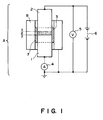
- the resistivity of carrier may be measured by using an apparatus (cell) A as shown in Figure 1 equipped with a lower electrode 1, an upper electrode 2, an insulator 3, an ammeter 4, a voltmeter 5, a constant-voltage regulator 6 and a guide ring 8.
- the cell A is charged with about 1 g of a sample carrier 7, in contact with which the electrodes 1 and 2 are disposed to apply a voltage therebetween, whereby a current flowing at that time is measured to calculate a resistivity.
- the above method is applicable not only to a carrier (inclusive of a coated carrier and a magnetic material-dispersion type carrier, but also to a carrier core.
- the carrier per may preferably satisfy a resistivity in the range of 10 8 - 10 14 ohm.cm.
- the triboelectric charge of a toner may be measured by using an apparatus shown in Figure 2.
- a magnetic brush (a mixture of a toner and a magnetic carrier) formed on a developer carrying member is taken and is charged in a metal container 22 for measurement provided with a 500-mesh screen 23 (the screen size being changed to an appropriate size not passing the magnetic powder) at the bottom as shown in Figure 2 and covered with a metal lid 24.
- the total weight of the container 22 is weighed and denoted by W 1 (g).
- an aspirator 21 composed of an insulating material at least with respect to a part contacting the container 22 is operated, and the toner in the container is removed by suction through a suction port 27 sufficiently (for about 1 min.) while controlling the pressure at a vacuum gauge 25 at 250 mmHg by adjusting an aspiration control valve 26.
- the reading at this time of a potential meter 29 connected to the container by the medium of a capacitor 28 having a capacitance C (I.LF) is denoted by V (volts.).
- the total weight of the container after the aspiration is measured and denoted by W 2 (g).
- the triboelectric charge Q (u.C/g) is calculated as:
- the measurement may suitably be performed in an environment of a temperature of 23 °C and a humidity of 65 %RH.
- the specific gravity of a carrier core or a carrier may be measured by "Truedenser” (available from Seishin Kigyo K.K.).
- the weight-average particle size of a toner may be measured by a Coulter counter (e.g., "Model TA-II", available from Coulter Electronics Inc.), to which an interface (available from Nikkaki K.K.) for providing a number-basis distribution and a volume-basis distribution, and a personal computer CX-1 (available from Canon K.K.) are connected.
- a Coulter counter e.g., "Model TA-II", available from Coulter Electronics Inc.
- an interface available from Nikkaki K.K.
- CX-1 available from Canon K.K.
- a 1 %-NaCI aqueous solution as an electrolyte solution is prepared by using a reagent-grade sodium chloride.
- a surfactant preferably an alkylbenzenesulfonic acid salt, is added as a dispersant, and 2 to 20 mg of a sample is added thereto.
- the resultant dispersion of the sample in the electrolyte liquid is subjected to a dispersion treatment for about 1 - 3 minutes by means of an ultrasonic disperser, and then subjected to measurement of particle size distribution in the range of 2 - 40 ⁇ m by using the above-mentioned Coulter counter Model TA-II with a 100 micron-aperture to obtain a number-basis distribution, from which a weight-average particle size is calculated.
- a carrier coating solution 15 parts of the block copolymer was dissolved in 85 parts of tetrahydrofuran to form a carrier coating solution.
- the solution was applied onto spherical magnetic ferrite core particles having an average particle size of 45 ⁇ m by using a coater ("Spira Cota" available from Okada Seiko K.K.), followed by preliminary drying at 80 °C for 20 min. and drying at 150 °C for 40 min. to prepare a resin-coated carrier having an average particle size of ca. 45 ⁇ m.
- the coated carrier showed a resistivity of 10 11 ohm.cm and a specific gravity of ca. 5.
- the coated carrier after the coating step showed a resin coating rate of 0.94 % and showed a good coating state as a result of observation through an electron microscope.
- a toner was prepared as follows.
- the above ingredients were preliminarily blended sufficiently by a Henschel mixer and then melt-kneaded three times through a three-roll mill. After cooling, the kneaded product was coarsely crushed into particles of ca. 1 - 2 mm and finely pulverized by an air jet pulverizer, followed by classification to obtain a negatively chargeable nonmagnetic cyan toner having a weight-average particle size of 8.3 am.
- the developer was charged in a full color laser copying machine (a remodeling of a commercially available machine "CLC-500" available from Canon K.K.) to effect an image formation test.
- a full color laser copying machine a remodeling of a commercially available machine "CLC-500” available from Canon K.K.
- the toner in the two-component type developer on the developing sleeve showed a triboelectric charge of -20 uc/g.
- the developing device was taken out of the re-modelled copying machine and the developing sleeve thereof was subjected to a blank rotation at 200 rpm for 40 minutes without forming images by using an external drive motor.
- the developing device was recharged in the remodelled copying machine, and the image formation test was resumed, whereby good toner images were formed without causing rough images at the halftone part.
- a carrier coating solution 15 parts of the block copolymer was dissolved in 85 parts of dioxane to form a carrier coating solution.
- the solution was applied onto spherical magnetic ferrite core particles having an average particle size of 45 ⁇ m preliminarily treated with methyltrimethoxysilane by using a coater ("Spira Cota" available from Okada Seiko K.K.), followed by preliminary drying at 80 °C for 20 min. and drying at 150 °C for 40 min. to prepare a resin-coated carrier having an average particle size of ca. 45 am.
- the coated carrier after the coating step showed a resin coating rate of 0.95 % and showed a good coating state as a result of observation through an electron microscope.
- a carrier coating solution 15 parts of the block copolymer and 1 part of tetraisopropyl titanate were dissolved in 85 parts of tetrahydrofuran to form a carrier coating solution.
- the solution was applied onto spherical magnetic ferrite core particles having an average particle size of 50 ⁇ m by using a coater ("Spira Cota" available from Okada Seiko K.K.), followed by preliminary drying at 80 °C for 20 min. and drying at 150 °C for 40 min. to prepare a resin-coated carrier having an average particle size of ca. 50 am.
- the coated carrier after the coating step showed a resin coating rate of 0.94 % and showed a good coating state as a result of observation through an electron microscope.
- a carrier coating solution 15 parts of the block copolymer was dissolved in 85 parts of dioxane to form a carrier coating solution.
- the solution was applied onto spherical magnetic ferrite core particles having an average particle size of 50 ⁇ m by using a coater ("Spira Cota" available from Okada Seiko K.K.), followed by preliminary drying at 80 °C for 20 min. and drying at 150 °C for 40 min. to prepare a resin-coated carrier having an average particle size of ca. 50 am.
- the coated carrier after the coating step showed a resin coating rate of 0.90 % and showed a good coating state as a result of observation through an electron microscope.
- a carrier coating solution 15 parts of the block copolymer and 1 part of methyltriethoxysilane were dissolved in 85 parts of dioxane to form a carrier coating solution.
- the solution was applied onto spherical magnetic ferrite core particles having an average particle size of 50 ⁇ m by using a coater ("Spira Cota" available from Okada Seiko K.K.), followed by preliminary drying at 80 °C for 20 min. and drying at 150 °C for 40 min. to prepare a resin-coated carrier having an average particle size of ca. 50 /1.m.
- the coated carrier after the coating step showed a resin coating rate of 0.90 % and showed a good coating state as a result of observation through an electron microscope.
- Mw 28,000
- a carrier coating solution 15 parts of the block copolymer was dissolved in 85 parts of tetrahydrofuran to form a carrier coating solution.
- the solution was applied onto spherical magnetic ferrite core particles having an average particle size of 50 ⁇ m by using a coater ("Spira Cota" available from Okada Seiko K.K.), followed by preliminary drying at 80 °C for 20 min. and drying at 150 °C for 40 min. to prepare a resin-coated carrier having an average particle size of ca. 50 ⁇ m.
- the coated carrier after the coating step showed a resin coating rate of 0.90 % and showed a good coating state as a result of observation through an electron microscope.
- Mw 95,000
- a carrier coating solution 15 parts of the block copolymer was dissolved in 95 parts of chlorobenzene to form a carrier coating solution.
- the solution was applied onto spherical magnetic ferrite core particles having an average particle size of 50 ⁇ m by using a coater ("Spira Cota" available from Okada Seiko K.K.), followed by preliminary drying at 80 °C for 20 min. and drying at 150 °C for 40 min. to prepare a resin-coated carrier having an average particle size of ca. 50 /1.m.
- the coated carrier after the coating step showed a resin coating rate of 0.90 % and showed a good coating state as a result of observation through an electron microscope.
- styrene/2-ethylhexyl methacrylate copolymer 40/60
- Mw corr. to the weight-average molecular weight of standard polystyrene according to gel permeation chromatography
- Mw 25,000
- a filming of spent toner on the carrier particle surface was clearly recognized as a result of observation of the carrier after the shaking through an electron microscope.
- a resin-coated carrier was prepared except for the use of a silicone resin ("KR 9706" available from Shin-Etsu Kagaku Kogyo K.K.) as the coating resin.
- KR 9706 available from Shin-Etsu Kagaku Kogyo K.K.
- the peeling state of the coating of the coated carrier was evaluated with reference to that in Comparative Example 1 as a result of observation through an electron microscope.
- the filming state on the coated carrier was evaluated with reference to that in Comparative Example 1 as a result of observation through an electron microscope.
- a negatively chargeable cyan toner having a weight-average particle size of 8.4 /1 .m was prepared in the same manner as in Example 1.
- the developer was charged in a full color laser copying machine (a remodeling of a commercially available machine "CLC-500" available from Canon K.K.). Before image formation, the developing device was taken out of the remodelled copying machines, and the developing sleeve thereof was subjected to a blank rotation at 200 rpm for 40 min. without forming images by using an external drive motor. Then, the developing device was re-set in the remodelled copying machine and used for an image formation test. As a measurement at an interruption of the image forming test, the toner in the two-component type developer on the developing sleeve showed a triboelectric charge of -20 uc/g.
- a binder resin which was a polycarbonate-polysiloxane block copolymer comprising 80 wt. % of a polycarbonate block of the above-mentioned formula (33) and 20 wt. % of the polydialkyl
- the kneaded product was coarsely crushed to a particle size of ca. 2 mm and then finely pulverized to a particle size of 50 ⁇ m by an air jet pulverizer.
- the finely pulverized product was then mechanically made spherical by "Mechano Mill MM-10" (available from Okada Seiko K.K.).
- the spherical finely pulverized product was classified to obtain carrier particles having an average particle size of 48 ⁇ m.
- the carrier was evaluated in the same manner as in Example 8, whereby good results were obtained in the shaking test and in the image forming test. The results are shown in Table 3.
- a binder resin which was a polycarbonate-polysiloxane block copolymer comprising 70 wt. % of a polycarbonate block of the above-mentioned formula (39) and 30 wt. % of
- the kneaded product was coarsely crushed to a particle size of ca. 2 mm and then finely pulverized to a particle size of 50 ⁇ m by an air jet pulverizer.
- the finely pulverized product was then mechanically made spherical by "Mechano Mill MM-10" (available from Okada Seiko K.K.).
- the spherical finely pulverized product was classified to obtain carrier particles having an average particle size of 54 ⁇ m.
- the carrier was evaluated in the same manner as in Example 8, whereby good results were obtained in the shaking test and in the image forming test. The results are shown in Table 3.
- a binder resin which was a polycarbonate-polysiloxane block copolymer comprising 70 wt. % of a polycarbonate block of the above-mentioned formula (35) and 30 wt. % of the polydialkyls
- the kneaded product was coarsely crushed to a particle size of ca. 2 mm and then finely pulverized to a particle size of 50 ⁇ m by an air jet pulverizer.
- the finely pulverized product was then mechanically made spherical by "Mechano Mill MM-10" (available from Okada Seiko K.K.).
- the spherical finely pulverized product was classified to obtain carrier particles having an average particle size of 48 ⁇ m.
- the carrier was evaluated in the same manner as in Example 8, whereby good results were obtained in the shaking test and in the image forming test. The results are shown in Table 3.
- a binder resin which was a polycarbonate-polysiloxane block copolymer comprising 50 wt. % of a polycarbonate block of the above-mentioned formula (36) and 20 wt. % of
- the kneaded product was coarsely crushed to a particle size of ca. 2 mm and then finely pulverized to a particle size of 50 ⁇ m by an air jet pulverizer.
- the finely pulverized product was then mechanically made spherical by "Mechano Mill MM-10" (available from Okada Seiko K.K.).
- the spherical finely pulverized product was classified to obtain carrier particles having an average particle size of 51 ⁇ m.
- the carrier was evaluated in the same manner as in Example 8, whereby good results were obtained in the shaking test and in the image forming test. The results are shown in Table 3.
- the carrier was evaluated in the same manner as in Example 8.
- a two-component type developer for developing an electrostatic image is constituted by a toner and a carrier.
- the carrier is composed of a magnetic material and a resin either coating or dispersing the magnetic material.
- the resin comprises a copolymer having structural units of the following formula [1] and [2]: wherein A denotes a C 1 - C 10 linear, branched or cyclic alkylidene group, aryl-substituted alkylidene group or arylenedialkylidene group, -O-, -S-, -CO-, -SO- or -S0 2 -; and R 1 - R 4 independently denote hydrogen, halogen, or a Ci - C 4 alkyl or alkenyl group; wherein R 5 denotes a C 2 - C 6 alkylene or alkylidene group; R 6 and R 7 denote a C 1 - C 3 alkyl group, a phenyl group or a substituted
Abstract


Description
- The present invention relates to a carrier for use in electrophotography, and a two component-type developer containing the carrier and a toner for developing electrostatic images.
- Hitherto, various electrophotographic processes have been disclosed in U.S. Patents Nos. 2,297,691; 3,666,363; 4,071,361; etc. In these processes, an electrostatic latent image is formed on a photoconductive layer by irradiating a light image corresponding to an original, and a toner having a polarity of charge opposite to that of the latent image is attached onto the latent image to develop the latent image. Subsequently, the resultant toner image is, after being transferred onto a transfer material such as paper, as desired, fixed , e.g., by heating, pressing, or heating and pressing, or with solvent vapor to obtain a copy.
- In the step of developing the latent image, toner particles charged to a polarity opposite to that of the latent image is attracted by electrostatic force to be caused to attach onto the latent image. Alternatively, in case of reversal development, toner particles having a triboelectric charge of the same polarity as that of the latent image is used. In general, methods for developing an electrostatic latent image with a toner can be classified into a developing method using a two component-type developer constituted by mixing a small amount of a toner with carrier and a developing method using a monocomponent-type developer constituted by a toner alone without containing a carrier.
- The carrier constituting the two component-type developer may generally be classified roughly into an electroconductive carrier and an insulating carrier.
- The electroconductive carrier may generally comprise oxidized or yet-unoxidized iron powder. The two component-type developer comprising iron powder carrier is accompanied with problems that the triboelectric chargeability of the toner is liable to be unstable and the resultant visible image formed by the developer is liable to be accompanied with fog. Further, along with continual use of the developer, toner particles adhere onto the surface of the iron powder carrier particles to increase the electrical resistivity of the carrier particles, so that the bias current decreases and the triboelectric charge is instabilized. As a result, the resultant toner image is liable to have a lower image density and be accompanied with increased fog.
- The insulating carrier representatively comprises a core material of a ferromagnetic material, such as iron, nickel or ferrite, uniformly coated with an insulating resin. The developer using this type of carrier is advantageous in that the adhesion of toner particles onto the carrier surface is remarkably less than in the case of the electroconductivity, and the developer is excellent in durability and has a long service life, so that the developer is particularly suitable for a high-speed electrophotographic copying machine.
- Such an insulating carrier is required to satisfy several requirements inclusive of: a durability that the coating layer covering the carrier core shows a sufficient wear resistance and a strong adhesion onto the core, an anti-soiling characteristic that the coating layer shows a good sticking prevention effect so as to prevent filming of the toner material on the carrier surface and a charging characteristic that a specific toner used in combination with the carrier is provided with a triboelectric charge of a desired polarity through friction with the carrier. The carrier particles are subjected to friction with the other carrier particles and toner particles within a developing device and, if the carrier coating surface is covered with a film of the attached toner, the charging characteristic becomes unstable.
- In order to prevent the soiling with a toner, it has been hitherto proposed to coat the carrier surface with various resins.
- For example, a carrier coated with a fluorine-containing resin, such as a tetrafluoroethylene copolymer has a low critical surface tension so that the toner soiling does not readily occur, but is poor in film forming characteristic so that it becomes difficult to sufficiently uniformly coat the carrier core and it is difficult to obtain a stable charging characteristic. The fluorine-containing resin also shows a poor adhesion with the core material and is liable to provide an insufficient wear resistance. Further, because of its position in the triboelectrification series, a fluorine-containing resin-coated carrier cannot provide a sufficient negative charge to a toner.
- On the other hand, a carrier coated with an acrylic resin, such as a styrene-methacrylate copolymer, shows good film-forming characteristic and good adhesion onto the core of the coating film. However, an acrylic resin shows a relatively high critical surface tension and is liable to suffer from soiling with toner on repetitive use, thus leaving some problem in respect of the life of the developer. Further, the wear resistance thereof is not sufficiently high while its surface hardness is relatively high.
- A silicone resin has a low surface energy and can decrease the soiling with toner, but shows a rather low mechanical strength so that the coating layer composed thereof is liable to be worn out while being stirred within the developing device. Thus, it is difficult to provide a stable charging characteristic. It is possible to use a polymer having a polydialkylsiloxane structure unit in mixture with another polymer, such as a styrene-acrylate copolymer. In this case, however, the polydialkylsiloxane-containing polymer is condensed at the surface and is liable to be preferentially lost during stirring within the developing device, so that it becomes difficult to stabilize the charging characteristic over a long period.
- Accordingly, it is still desired to develop a carrier for a two-component type developer, capable of showing a satisfactory charging characteristic, excellent soiling resistance and good successive copying characteristic on a large number of sheets and also capable of providing high-quality toner images.
- A two-component type developer comprising a toner and a magnetic carrier is applied in a prescribed coating layer thickness by a developer layer thickness-regulating member on a developing sleeve enclosing a magnet inside thereof and conveyed in utilization of a magnetic force to a developing zone formed between a photosensitive member and the developing sleeve.
- Between the photosensitive member and the developing sleeve, a prescribed developing bias voltage is applied so as to develop an electrostatic latent image with a toner in the developing zone.
- As important requirements, the magnetic carrier is required to show appropriate charging characteristic, withstand voltage resistant to an applied voltage, impact resistance, wear resistance, anti-spent characteristic, developing characteristic and productivity.
- Regarding the anti-spent characteristic, for example, in the case of a continual use of a developer for a long period, a so-called "spent toner" (a filming or melt-sticking of a toner) is attached onto the carrier surface, thus resulting in a deterioration of the developer and thus an image quality deterioration of the developed images.
- Generally, in case where a carrier has too large a specific gravity, a large load is applied onto the developer at the time of applying the developer in a prescribed layer thickness on the sleeve by the above-mentioned developer layer thickness-regulating means or at the time of stirring the developer within the developing device, so that (a) toner filming and (a) toner deterioration are liable to be caused during the long use of the developer, thus causing deterioration of the developer and image quality deterioration of the developed images. A developer containing a carrier liable to cause the above difficulties (a) and (b) requires a periodical exchange thereof or improvement of the carrier regarding the durability and anti-spent characteristic so as to alleviate the difficulties (a) and (b), thus prolonging the life of the developer.
- In order to cope with the above problems, it is possible to use a carrier comprising magnetic particles dispersed within a binder resin, e.g., a magnetic material-dispersion type carrier produced by pulverization, e.g., as proposed in Japanese Laid-Open Patent Application (JP-A) 56-66134.
- It is also possible to use a magnetic material-dispersion type carrier produced by polymerization disclosed by JP-A 61-6959.
- However, the above-mentioned magnetic material-dispersion type developers are accompanied with a difficulty that, unless a large amount of magnetic material is incorporated in a carrier particle, the carrier shows a small saturation magnetization relative to the particle size and is liable to attach to the photosensitive member at the time of developing. As a result, it is necessary to install mechanisms for replenishing the developer and recovering the attached carrier within the image forming apparatus. Thus, the magnetic material-dispersion type carrier is not sufficiently satisfactory as a measure for prolonging the life of the developer.
- On the other hand, in case where a large amount of magnetic material is incorporated in the above-mentioned magnetic material-dispersion type carrier, the magnetic material having a low resistivity is increased in amount to be exposed to the carrier surface to lower the resistivity of the carrier, so that the resultant image quality is liable to be lowered due to leakage of the bias voltage applied during the development.
- Further, in the case where a large amount of magnetic material is incorporated in the magnetic material-dispersion type carrier, the amount of the magnetic material is increased relative to the binder resin to make the carrier less resistant to a mechanical impact, So that the magnetic material is liable to drop off the carrier at the time of applying the developer in a prescribed layer thickness on the sleeve by the developer layer thickness-regulating means. As a result, the developer is liable to be deteriorated again.
- Further, the fine particles resultant after the dropping or breakage of the magnetic material have a low magnetic property so that they cannot be held on the sleeve at the time of development to attach to the photosensitive member, thus generating image defects.
- As the binder resin for dispersing magnetic material particles to produce a magnetic material-dispersion type carrier, various resins have been known and used, such as acrylic resin, vinyl resin, styrene-acrylate copolymer, styrene-butadiene copolymer, ethylene-vinyl acetate copolymer, and further, polyester resin, epoxy resin, phenolic resin, urea resin, polyurethane resin, polyimide resin, cellulosic resin, low-molecular weight polypropylene, vinyl chloride resin, vinyl acetate resin, copolymers of these resins, and petroleum resin.
- However, a resinous carrier composition utilizing a binder resin as described above in mixture with a magnetic material cause a decrease in impact resistance and wear resistance particularly when used for a long period, and is therefore liable to cause the breakage or wearing of the carrier per se, thus failing to show a sufficient charging characteristic and also resulting in fine carrier particles which adhere to the photosensitive member during development and cause fog at the non-image parts of the developed images. In addition, as the carrier binder resin has a relatively close chemical composition to a toner binder resin (e.g., styrene-butadiene copolymer, styrene-acrylate copolymer or polyester resin), the toner readily adheres to the carrier to change and/or lower the triboelectric charging ability, so that it is difficult to provide a two-component type developer which provides high-quality images, and are excellent in successive image formation characteristic and highly stable.
- In order to alleviate the above problems, it is possible to use a curable resin, such as epoxy resin, but the use of a curable resin is accompanied with a problem that a foreign matter is rather accumulated on the surface to result in a remarkable change in triboelectric charging characteristic.
- Accordingly, in order to realize a magnetic material-dispersion type carrier containing an increased amount of magnetic material, it has been considered necessary to use a binder resin which shows a good adhesion to the magnetic material and also a good dispersion of the magnetic material.
- Thus, a magnetic material-dispersion type carrier showing good soiling resistance and durability suitable for successive image formation on a large number of sheets.
- A generic object of the present invention is to provide a carrier for use in electrophotography (hereinafter sometimes referred to as "electrophotographic carrier" or simply "carrier") having solved the above-mentioned problems.
- A more specific object of the present invention is to provide an electrophotographic carrier which is excellent in wear resistance and impact resistance.
- Another object of the present invention is to provide an electrophotographic carrier which is not readily stained or soiled by the toner.
- Another object of the present invention is to provide an electrophotographic carrier coated with a highly durable resin which has sufficient mechanical strength against wearing and impact.
- Another object of the present invention is to provide a resin-coated electrophotographic carrier which is excellent in surface releasability, less susceptible to soiling with the toner and is excellent in stability.
- Another object of the present invention is to provide a magnetic material dispersion-type electrophotographic carrier less susceptible to soiling with the toner.
- Another object of the present invention is to provide a magnetic material dispersion-type electrophotographic carrier excellent in wear resistance and impact resistance.
- Another object of the present invention is to provide a magnetic material dispersion-type electrophotographic carrier which is less liable to stick to a photosensitive member.
- A further object of the present invention is to provide a two-component type developer capable of providing high-quality toner images.
- Another object of the present invention is to provide a two-component type developer excellent in successive image forming characteristic on a large number of sheets.
- According to the present invention, there is provided a carrier for use in electrophotography, comprising a magnetic material and a resin, said resin comprising a copolymer having structural units of the following formulae [1] and [2]:


- According to another aspect of the present invention, there is provided a two-component type developer for developing an electrostatic image, comprising a toner and the above-mentioned carrier.
- These and other objects, features and advantages of the present invention will become more apparent upon a consideration of the following description of the preferred embodiments of the present invention taken in conjunction with the accompanying drawings.
-
- Figure 1 is a schematic view showing an apparatus for measuring an electrical resistivity of a carrier.
- Figure 2 is a schematic illustration of an apparatus for measuring a triboelectric charge of a toner in a two-component type developer.
- In the present invention, a copolymer showing an improved surface releasability without causing a lowered carrier strength is used as a carrier-forming material in order to provide a highly durable and highly stable carrier having solved the above-mentioned problems.
- The copolymer used in the present invention is characterized by having a polycarbonate unit providing a good impact resistance and a polydialkylsiloxane unit and is provided with an improved surface lubricity while retaining the impact resistance.
- More specifically, the copolymer used in the present invention is characterized by having a structural unit of the formula [1 ] and a structural unit of the formula [2] described above and may preferably be in the form of a block copolymer having at least one block copolymer unit including a polycarbonate unit and a polysiloxane unit and represented by the following formula [3]:

- The structural unit [1] of the copolymer may be derived, e.g., from a diol represented by the following formula:

- Further, the structural unit [2] of the copolymer may be derived, e.g., from a polysiloxane-diol represented by the following formula [2A]:

- Some examples of diphenol compounds providing the polycarbonate unit (structural unit [1]) of the copolymer are enumerated below, but they are not exhaustive:


- Among the above, Compounds Nos. 3, 8, 16, 19 and 21 are especially preferred.
- next, some preferred examples of polyorganosiloxanes giving the structural unit [2] of the copolymer are enumerated below, but they are not exhaustive:


- The copolymer used in the present invention may be synthesized by polymerization using a diol and a polyorganosiloxane as described above through the phosgene process, the ester exchange process or the chloroformate intermediate process. It is suitable to apply polymerization according to the phosgene process in a solution system in order to stabilize the randomness of the copolymerization. It is possible to apply, e.g., a process disclosed in U.S. Patent No. 3,781,378 (corr. to JP-A 48-64199) in order to produce a polycarbonate block copolymer.
- The copolymer used in the present invention may preferably have a weight-average molecular weight of 10,000 - 100,000 in view of the wear resistance and durability.
- The carrier of the present invention may suitably have an average particle size (diameter) of 5 - 100 am. If the carrier particle size is below 5 µm, the carrier is liable to attach to the photosensitive member. In excess of 100 µm, a large shearing force is applied to the developer within the developing device, thus being liable to cause deterioration of the developer, particularly separation of external additive from the toner and shape change of the toner. Too large a particle size provides a smaller specific surface area, so that a smaller amount of toner is retained by the carrier, thus being liable to provide images with lower definition.
- In the two-component type developer of the present invention, it is preferred to select a combination of a carrier and a toner so as to provide a toner triboelectric charge of 5 - 50 µc/g in terms of an absolute value through friction between the carrier and the toner.
- Hereinbelow, a case of using the copolymer as a coating material on a magnetic carrier core and a case of using the copolymer as a binder resin for a magnetic material-dispersion type carrier will now be described in further detail.
- In the case of using the copolymer as a coating material on a carrier core, the carrier surface releasability is improved so that it is possible to effectively prevent the lowering in carrier life due to the soiling with the toner. Further, the coating solution can be uniformized to prevent a lowering in strength of the carrier coating layer, thus providing an improved durability. As a result, a developer comprising the carrier of the present invention is excellent in successive copying characteristic and stability. It is generally preferred that the copolymer has a higher glass transition point so as to provide an improved thermal stability.
- The copolymer used in the present invention can provide a clear solution when dissolved in a solvent, thus providing a sufficiently tough resin coating. This is particularly true when a dialkylsiloxane-block diphenol compound of the above formula [2A] is used for copolymerization so as to effect the copolymerization in a sufficiently random manner. This is presumably effective in preventing the growth of a long chain polydialkylsiloxane block leading to a lower solubility and a turbid solution. Further, it is also possible to prevent the formation of a polymer chain of polydialkylsiloxane alone, thus providing a copolymer showing stable properties.
- Such a coated carrier may be formed, e.g., by dissolving the copolymer in an appropriate solvent including, e.g., an aromatic solvent, such as benzene, toluene or xylene; a halogenated compound, such as dichloromethane, trichloromethane or chlorobenzene; or a cyclic ether, such as tetrahydrofuran, tetrahydropyrane or dioxane, applying the resultant solution onto the surfaces of the magnetic carrier core particles, and drying the resultant coating solution film to form a resin film on the magnetic carrier core surfaces.
- The polycarbonate-polysiloxane block copolymer may preferably have a weight-average molecular weight of 10,000 - 100,000. If the molecular weight is below 10,000, the durability is liable to be lowered. If the molecular weight exceeds 100,000, the coating solution is caused to have a high viscosity, so that it is difficult to form a uniform coating in a prescribed amount.
- In a preferred embodiment, the copolymer may be dissolved in a suitable solvent (e.g., dichloromethane) to form a carrier coating solution, and the solution maybe applied onto a magnetic ferrite carrier by means of an appropriate applicator ("Spira Cota", mfd. by Okada Seiko K.K.). After the application, the coated product may be preliminarily dried at 70 - 80 °C to evaporate the solvent, followed by a heat treatment for 0.5 - 1 hour at 120 - 160 °C. The coating resin amount of the coated carrier may appropriately be selected so as to satisfy desired durability and charging characteristic, but may generally preferably be in the range of 0.01 - 30 wt. % of the carrier core. Below 0.01 wt. %, the coating effect is low.
- More specifically, the resin coating amount CW (wt. %) may depend on the true specific gravity Z of the carrier core material and may preferably be within the range of 1/2Z ≦ CW < 50/Z, more preferably in the range of 1/Z ≦
CW 25/Z. - The magnetic carrier core material may comprise particles of a magnetic material, such as iron or ferrite.
- In order to enhance the adhesion at the boundary between the coating copolymer and the carrier core, it is possible to apply an adhesion promoter, examples of which may include: silane coupling agents, such as methyltrimethoxysilane, methyltriethoxysilane, vinyltriethoxysilane, vinyltris(methoxyethoxysilane), vinyltriacetoxysilane, y-methacryloxypropyltrimethoxysilane, y-aminopropyltriethoxysilane, y-(aminoethyl)-aminopropyltriethoxysilane, y-glycidoxypropyltrimethoxysilane, y-mercaptopropyltrimethoxysilane, β-(3,4-epoxycyclohexyl)ethyltrimethoxysilane, and y-chloropropyltrimethoxysilane; organic titanium compounds, such as tetraisopropyl titanate, tetraisopropyl titanate polymer, tetrabutyl titanate tetrabutyl titanate polymer, tetrastearyl titanate, 2-ethylhexyl titanate, isopropoxytitanium stearate, titanium acetylacetonate and titanium lactate; and organic phosphate-based adhesion promoters. These compounds may be used singly or in mixture of two or more species. These compounds may be applied in advance onto the carrier core, followed by coating with the copolymer of the present invention. Alternatively, it is also possible to admix such an adhesion promoter with the copolymer of the present invention, and then apply the admixture onto the carrier core at a time.
- The copolymer used in the present invention may be used in mixture with another resin within an extent of not lowering the effect of the copolymer. Examples of such another resin may include: acrylic resin, styrene-acrylate copolymer resin, ethylene-vinyl acetate copolymer resin, polyester resin, polyethylene resin, polypropylene resin, polyvinylcarbazole resin, phenoxy resin, polycarbonate resin, polyvinyl butyral resin, polystyrene resin, polyvinyl acetate resin, polyallylate resin, and polysulfone resin.
- The coated carrier according to the present invention may preferably have a resistivity in the range of 108 - 1014 ohm.cm.
- The polycarbonate-polydiorganosiloxane block copolymer can well disperse magnetic material particles and firmly bond with the magnetic material particles. As a result, the copolymer may suitably be used as a binder resin of the magnetic material-dispersion type carrier to solve the problems of the prior art.
- In the case of using the polycarbonate-polydiorganosiloxane copolymer as the binder resin of the magnetic material-dispersion type carrier, the copolymer may preferably have a weight-average molecular weight in the range of 10,000 to 50,000. If the molecular weight is below 10,000, the durability is lowered. In excess of 50,000, the melt viscosity of the copolymer at the time of melt-kneading of the copolymer with the particles of the magnetic material is liable to be excessively high, so that a satisfactory melt-kneading is liable to be difficult.
- The polycarbonate-polydiorganosiloxane block copolymer may suitably have a glass transition point below 155 °C so as to provide a good processability at the time of melt-kneading. By using the copolymer as a binder resin of the magnetic material-dispersion type carrier, it becomes possible to provide improved wear resistance and anti-toner soiling characteristic and also suppress the toner deterioration. This is presumably because the copolymer of the present invention is rich in lubricity than an ordinary binder resin, thus resulting in an improved anti-toner soiling characteristic and also a reduced shear stress applied to the toner.
- Examples of the magnetic material used in the magnetic material-dispersion type carrier may include: ferromagnetic metals, such as iron, cobalt, and nickel, and alloys of these metals, and compounds, such as magnetite and hematite, containing an element showing ferromagnetism, such as iron, cobalt and nickel. The magnetic material may preferably have a saturation magnetization of 10 - 100 emu/g as measured at a magnetic field of 10 kilo-oersted by means of a tester (e.g., "VSM" available from Toei Kogyo K.K.).
- The magnetic material may preferably have an average primary particle size of at most 2.0 am. If the particle size exceeds 2.0 am, the resultant carrier particles are liable to have inferior surface state and have a charging ability which is unstable due to a change in environmental condition. The magnetic material fine particles may preferably have a resistivity of at most 109 ohm.cm. The magnetic material may preferably be contained in a proportion of at least 30 wt. %, further preferably at least 50 wt. %, in the carrier composition. Below 30 wt. %, the resultant carrier particles are liable to attach to the photosensitive member and the control of the electrical resistivity of the carrier is liable to be difficult.
- Thus, the attachment of the magnetic material-dispersion type carrier according to the present invention onto the photosensitive member can be suppressed, and the ability of charging the carrier can be effectively controlled. In this regard, it is particularly preferred to moderately control the electrical resistivity of the carrier so as not to provide the toner with an excessive charge (i.e., a so-called charge-up phenomenon) under a low humidity condition.
- In the present invention, it is possible to prepare carriers with various properties by adjusting the particle size, electrical resistivity and content of the magnetic material fine particles.
- The magnetic material-dispersion type carrier may preferably have a true specific gravity of 1.5 - 5.0, further suitably 1.5 - 4.5. If the true specific gravity exceeds 5.0, a large load is applied onto the two-component type developer within the developing device, thus being liable to deteriorate the developer. If the true specific gravity is below 1.5, it is difficult to provide a magnetic force sufficient to suppress the attachment of the carrier onto the photosensitive member. The true specific gravity of the carrier may be measured by using, e.g., "Truedenser" (trade mark) available from Seishin Kigyo K.K.
- The carrier of the present invention may suitably have an electrical resistivity of 107 - 1015 ohm.cm, preferably 108 - 1014 ohm.cm. If a carrier having a resistivity of below 107 ohm.cm is used in a development method applying a bias voltage, some current is liable to leak from the developing sleeve to the photosensitive member in the developing region, so that it becomes difficult to obtain good toner images. Above 1015 ohm.cm, the charge-up phenomenon is liable to occur in a low humidity environment to result in image difficulties, such as a low density, transfer failure and fog.
- The carrier may preferably have a sphericity (long axis/short axis ratio) of at most 2. If the sphericity exceeds 2, the intended effects are liable to be diminished regarding the effect of reducing the shear stress applied to the developer and the effect of improving the fluidity of the resultant developer.
- The sphericity of below 2 may be accomplished by rounding the carrier particles by thermally melting the surfaces thereof or by a mechanical treatment.
- The carrier according to the present invention may be produced through various processes including: a process wherein the binder resin and the magnetic material fine particles are blended in an appropriate ratio and melt-kneaded at an appropriate temperature by a hot-melt kneading means such as a three-roll mill or an extruder, followed by cooling, pulverization and classification; and a process wherein the binder resin (copolymer) is dissolved in an appropriate solvent, and the magnetic material is blended therewith to form a slurry, which is then formed into particles and dried by a spray dryer. In any process, it is important to uniformly disperse the magnetic material fine particles within the carrier particles.
- The magnetic material-dispersion type carrier prepared through such a process can be further coated with a resin for the purpose of further controlling the resistivity and adjusting the surface property to some extent.
- The two-component type developer according to the present invention may be prepared by blending 10 - 1000 wt. parts, preferably 30 - 500 wt. parts, of the carrier with 10 wt. parts of a toner.
- The toner used in the present invention may suitably have a weight-average particle size of 1 - 20 am, preferably 4 - 13 am.
- The toner used in the present invention, when used in combination with a hot-pressure roller fixing apparatus equipped with an oil applicator, may comprise a binder resin, examples of which may include: polystyrene; polymers of styrene derivatives, such as poly-p-chlorostyrene, and polyvinyltoluene; styrene copolymers, such as styrene-p-chlorostyrene copolymer, styrene-vinyltoluene copolymer, styrene-vinylnaphthalene copolymer, styrene-acrylate copolymer, styrene-methacrylate copolymer, styrene-methyl a-chloromethacrylate copolymer, styrene-acrylonitrile copolymer, styrene-vinyl methyl ketone copolymer, styrene-butadiene copolymer, styrene-isoprene copolymer, and styrene-acrylonitrile-indene copolymer; polyvinyl chloride, phenolic resin, natural or modified phenolic resin, natural or modified maleic acid resin, acrylic resin, methacrylic resin, polyvinyl acetate, silicone resin, polyester resin, polyurethane resin, polyamide resin, furan resin, epoxy resin, xylene resin, polyvinyl butyral, terpene resin, coumarone-indene resin and petroleum resin.
- On the other hand, the toner for use in combination with a hot-pressure roller fixing apparatus using little or no oil, is required to show a sufficient adhesion onto a toner image supporting member as an important characteristic. A toner fixable with less heat energy is generally liable to cause blocking or caking during storage or in the developing device, so that this problem will also require a consideration. Accordingly, for the toner to be used in combination with a hot-pressure roller fixing apparatus with little or no oil application, the selection of the binder resin becomes more important. Preferred binder resins may include crosslinked styrene copolymers and crosslinked polyesters.
- Examples of the comonomer to be used in combination with a styrene monomer may include vinyl monomers, including: monocarboxylic acids having a double bond and substitution derivatives thereof, such as acrylic acid, methyl acrylate, ethyl acrylate, butyl acrylate, dodecyl acrylate, octyl acrylate, 2-ethylhexyl acrylate, phenyl acrylate, methyl methacrylate, ethyl methacrylate, butyl methacrylate, octyl methacrylate, acrylonitrile, methacrylonitrile, and acrylamide; dicarboxylic acids having a double bond and substitution derivatives thereof, such as maleic acid, butyl maleate, methyl maleate, and dimethyl maleate; vinyl esters, such as vinyl acetate and vinyl benzoate; polyolefines, such as ethylene, propylene and butylene; vinyl ketones, such as vinyl methyl ketone, and vinyl hexyl ketone; and vinyl ethers, such as vinyl methyl ether and vinyl ethyl ether. These comonomers may be used singly or in combination of two or more species.
- The crosslinking agent may principally comprise a compound having at least two polymerizable double bonds. Examples thereof may include: aromatic divinyl compounds, such as divinylbenzene, and divinylnaphthalene; carboxylic acid esters having two double bonds, such as ethylene glycol diacrylate, ethylene glycol dimethacrylate, and 1,3-butanediol dimethacrylate; divinyl compounds, such as divinylaniline, divinyl ether, divinyl sulfide and divinyl sulfone; and compounds having three or more ethylenic double bonds. These compounds may be used alone or in mixture. At the time of synthesis of a binder resin, the crosslinking agent may preferably be used in a proportion of 0.01 - 10 wt. %, further preferably 0.05 - 5 wt. %, based on the binder resin, so as to provide good anti-offset characteristic and fixability.
- In the case of using a pressure-fixation system, it is possible to use a binder resin for a pressure-fixable toner, examples of which may include: polyethylene, polypropylene, polymethylene, polyurethane elastomer, ethylene-ethyl acrylate copolymer, ethylene-vinyl acetate copolymer, ionomer resin, styrene-butadiene copolymer, styrene-isoprene copolymer, linear saturated polyester, and paraffin.
- The toner used in the present invention may preferably be used in combination with a charge control agent which is incorporated in (internally added to) or blended with (externally added to) the toner particles. By the addition of a charge control agent, it becomes possible to effect an optimum charge control depending on a developing system used and provide a further stable balance between the toner particle size distribution and the toner charge. Examples of a positive charge control agent may include: nigrosine and modified products thereof with aliphatic acid metal salts; quaternary ammonium salts, such as tributylbenzylammonium-1-hydroxy-4-naphthosulfonate, and tetrabutylammonium tetrafluoroborate; and organic tin compounds, such as dibutyltin oxide, dioctyltin oxide, dicyclohexyltin oxide, diorganotin oxide, dibutyltin borate, dioctyltin borate, and dicyclohexyltin borate. These compounds may be used singly or in combination of two or more species. Among these, nigrosin-based compounds and quaternary ammonium salts are particularly preferred.
- Further, it is also possible to use as a positive charge control agent a homopolymer of a nitrogen-containing monomer represented by the formula:

- Alternatively, in the present invention, it is also possible to use a negative charge control agent, such as organic metal salts, organic metal complexes, and chelate compounds. Among these, acetylacetone metal complexes (inclusive of monoalkyl-substituted and dialkyl-substituted derivatives), salicylic acid metal complexes (inclusive of monoalkyl-substituted and dialkyl-substituted derivatives), and their corresponding salts are preferred. Salicylic acid-based metal complexes or salicylic acid-based salts are particularly preferred. Specific examples of preferred negative charge control agent may include: aluminum acetylacetonate, iron (II) acetylacetonate, 3,5-di-tert-butylsalicylic acid chromium complex or salt, and 3,5-di-tert-butylsalicylic acid zinc complex or salt.
- The above-mentioned charge control agents (except for those functioning also as a binder resin) may preferably be used in the form of fine particles having a number-average particle size of at most 4 I.Lm, further preferably at most 3 I.Lm.
- When internally added to the toner, the above charge control agent may preferably be used in a proportion of 0.1 - 20 wt. parts, particularly 0.2 - 10 wt. parts, per 100 wt. parts of the binder resin.
- The developer according to the present invention may preferably contain silica fine powder. By using a combination of a toner and silica fine powder, the silica fine powder is caused to be present between the toner particles and the carrier particles, thereby remarkably reducing the friction or wearing therebetween. As a result, the toner and the carrier are caused to have a prolonged life and stable chargeability and charging characteristic, so that it is possible to provide a two-component type developer comprising the toner and the carrier showing better performances even in a prolonged period of use.
- Particularly, in the case of using a toner having a weight-average particle size of at most 10 am, the specific surface area per unit weight of the toner is increased than in the case of using a smaller toner, so that the frequency of contact between the carrier and the toner particle surface is increased and the soiling of the carrier is promoted. Even in such a case, a good two-component type developer can be obtained by the addition of silica fine powder.
- The silica fine powder may be either dry process silica or wet process silica but may preferably be dry process silica fine powder in view of the anti-filming characteristic and durability.
- Herein, the dry process silica means silica fine powder produced, e.g., by vapor-phase oxidation of a silicon halide.
- On the other hand, the wet process silica fine powder may be produced through various known processes.
- The silica fine powder used herein may include fine powders of: anhydrous silicon dioxide (colloidal silica); and silicates, such as aluminum silicate, sodium silicate, potassium silicate, magnesium silicate and zinc silicate.
- A particularly good result may be obtained by using silica fine powder having a specific surface area of at least 30 m2/g, preferably 50 - 400 m2/g, as measured by the BET method using nitrogen adsorption. It is suitable to use 0.1 - 8 wt. parts, preferably 0.1 - 5 wt. parts, of silica fine powder per 100 wt. parts of the toner.
- In the case of using the toner as a positively chargeable toner, it is preferred that the silica fine powder added in order to prevent the wearing of the toner and the surface soiling of the carrier is positively chargeable rather than being negatively chargeable, so as not to impair the charging stability. For the same reason, it is preferred to use negatively chargeable silica fine powder for a negatively chargeable toner.
- Silica fine powder is generally negatively chargeable. In order to obtain a positively chargeable silica fine powder, the silica fine powder as produced as described above may be treated with a silicone oil having an organic group having a side chain including at least one nitrogen atom, a nitrogen-containing silane coupling agent or both of these.
- Examples of the treating agents may include: aminopropyltrimethoxysilane, aminopropyltriethoxysilane, dimethylaminopropyltrimethoxysilane, diethylaminopropyltrimethoxysilane, dipropylaminopropyltrimethox- ysilane, dibutylaminopropyltrimethoxysilane, monobutylaminopropyltrimethoxysilane, dioctylaminopropyl- trimethoxysilane, dibutylaminopropyltrimethoxysilane, dibutylaminopropyltrimethoxysilane, dibutylaminopropylmonomethoxysilane, dimethylaminophenyltriethoxysilane, trimethoxysilyl-y-propyl- phenylamine, and trimethoxysilyl-y-propylbenzylamine. Further examples may include: trimethoxysilyl-y-propylpiperidine, trimethoxysilyl-y-propylmorpholine, trimethoxysilyl-y-propylimidazole, hexamethyldisilazane, trimethoxysilane, trimethylchlorosilane, trimethylethoxysilane, dimethyldichlorosilane, methyltrichlorosilane, allyldimethylchlorosilane, allylphenyldichlorosilane, benzyldimethylcholrosilane, bromomethyl- dimethylchlorosilane, α-chloroethyltrichlorosilane, β-chloroethyltrichlorosilane, chloromethyldimethylchlorosilane, triorganosilylmercaptans such as trimethylsilylmercaptan, triorganosilyl acrylates, vinyl- dimethylacetoxysilane, dimethylethoxysilane, dimethyldimethoxysilane, diphenyldiethoxysilane, hexamethyldisiloxane, 1,3-divinyltetramethyldisiloxane, 1,3-diphenyltetramethyldisiloxane, and dimethylpolysiloxane having 2 to 12 siloxane units per molecule and containing each one hydroxyl group bonded to Si at the terminal units. These may be used alone or as a mixture of two or more compounds. The treating agent may suitably be used in an amount of 1 - 40 wt. % based on the silica fine particles.
- In place of the above-mentioned silica fine powder, it is possible to use titanium oxide (Ti02) fine powder having a BET specific surface area of 50 - 400 m2/g. It is also possible to use a mixture of such silica fine powder and titanium oxide fine powder.
- To the toner constituting the developer according to the present invention, it is also possible to add fine powder of a fluorine-containing polymer, such as polytetrafluoroethylene, polyvinylidene fluoride, or tetrafluoroethylene-vinylidene fluoride copolymer.
- As the colorant for the toner, it is possible to use a dye and/or a pigment known heretofore. Examples thereof may include: carbon black, Phthaloycanine Blue, Peacock Blue, Permanent Red, Lake Red, Rhodamine Lake, Hansa Yellow, Permanent Yellow and Benzidine Yellow. The colorant may be added in an amount of 0.1 - 20 wt. parts, preferably 0.5 - 20 wt. parts, per 100 wt. parts of the binder resin. In order to provide a fixed toner image having a good transparency or an OHP film, the colorant may preferably be added in a proportion of at most 12 wt. parts, further preferably 0.5 - 9 wt. parts, per 100 wt. parts of the binder resin.
- The toner constituting the developer according to the present invention can further contain a wax, such as polyethylene, low-molecular weight polypropylene, microcrystalline wax, carnauba wax, sasol wax or paraffin wax in order to improve the releasability at the time of hot pressure fixation. In addition to the above-mentioned additives, it is also possible to add other additives as desired in order to provide the developer according to the present invention.
- In preparing the toner constituting the developer according to the present invention, the binder resin of a vinyl-type or non-vinyl-type thermoplastic resin, a pigment or dye as the colorant, an optional charge control agent and other additives may be sufficiently blended in a mixer such as a ball mill and then melt-kneaded by a hot kneading means, such as heated rollers, a kneader or an extruder to compatibly knead the resins and disperse or dissolve therein the pigment or dye. The thus-kneaded product is thereafter cooled for solidification, pulverized and strictly classified to obtain toner particles. The toner particles can be used as a toner as it is but may preferably be mixed with externally added optional silica fine powder or titanium oxide fine powder by means of a blender such as a Henschel mixer to provide a toner. The toner containing an external additive may be blended with the carrier mentioned above to provide a two-component type developer according to the present invention.
- Now, methods for measuring various properties of a carrier and a toner will be described.
- The average particle sizes of a carrier core and a carrier may be measured by taking at least 300 particles of a sample carrier core or a sample carrier at random through an optical microscope and measuring the average horizontal FERE diameter as an average particle size of the carrier core or the carrier by an image analyzer (e.g., "
Luzex 3" available from Nireco K.K.). - The resistivity of carrier may be measured by using an apparatus (cell) A as shown in Figure 1 equipped with a lower electrode 1, an
upper electrode 2, aninsulator 3, anammeter 4, avoltmeter 5, a constant-voltage regulator 6 and aguide ring 8. For measurement, the cell A is charged with about 1 g of asample carrier 7, in contact with which theelectrodes 1 and 2 are disposed to apply a voltage therebetween, whereby a current flowing at that time is measured to calculate a resistivity. The above method is applicable not only to a carrier (inclusive of a coated carrier and a magnetic material-dispersion type carrier, but also to a carrier core. In any case, the carrier per may preferably satisfy a resistivity in the range of 108 - 1014 ohm.cm. The resistivity values described herein are based on measurement under the conditions of the contact area between thecarrier 7 and theelectrode 1 or 2 = about 2.3 cm2, the carrier thickness = about 1 mm, the weight of theupper electrode 2 = 275 g, and the applied voltage = 100 volts. - The triboelectric charge of a toner may be measured by using an apparatus shown in Figure 2. A magnetic brush (a mixture of a toner and a magnetic carrier) formed on a developer carrying member is taken and is charged in a
metal container 22 for measurement provided with a 500-mesh screen 23 (the screen size being changed to an appropriate size not passing the magnetic powder) at the bottom as shown in Figure 2 and covered with ametal lid 24. The total weight of thecontainer 22 is weighed and denoted by W1 (g). Then, anaspirator 21 composed of an insulating material at least with respect to a part contacting thecontainer 22 is operated, and the toner in the container is removed by suction through asuction port 27 sufficiently (for about 1 min.) while controlling the pressure at avacuum gauge 25 at 250 mmHg by adjusting anaspiration control valve 26. The reading at this time of apotential meter 29 connected to the container by the medium of acapacitor 28 having a capacitance C (I.LF) is denoted by V (volts.). The total weight of the container after the aspiration is measured and denoted by W2 (g). Then, the triboelectric charge Q (u.C/g) is calculated as:
- The measurement may suitably be performed in an environment of a temperature of 23 °C and a humidity of 65 %RH.
- The specific gravity of a carrier core or a carrier may be measured by "Truedenser" (available from Seishin Kigyo K.K.).
- The weight-average particle size of a toner may be measured by a Coulter counter (e.g., "Model TA-II", available from Coulter Electronics Inc.), to which an interface (available from Nikkaki K.K.) for providing a number-basis distribution and a volume-basis distribution, and a personal computer CX-1 (available from Canon K.K.) are connected.
- For measurement, a 1 %-NaCI aqueous solution as an electrolyte solution is prepared by using a reagent-grade sodium chloride. Into 100 to 150 ml of the electrolyte solution, 0.1 to 5 ml of a surfactant, preferably an alkylbenzenesulfonic acid salt, is added as a dispersant, and 2 to 20 mg of a sample is added thereto. The resultant dispersion of the sample in the electrolyte liquid is subjected to a dispersion treatment for about 1 - 3 minutes by means of an ultrasonic disperser, and then subjected to measurement of particle size distribution in the range of 2 - 40 µm by using the above-mentioned Coulter counter Model TA-II with a 100 micron-aperture to obtain a number-basis distribution, from which a weight-average particle size is calculated.
- Hereinbelow, the present invention will be described based on Examples, which however should not be construed to restrict the scope of the invention. In the following description, "%" and "part(s)" are all by weight, and Mw and Mn denote a weight average molecular weight and a number-average molecular weight, respectively.
- A spherical magnetic ferrite carrier core was coated with a coating resin, which was a polycarbonate-polysiloxane block copolymer (Mw = 25,000) comprising 90 wt. % of a polycarbonate block represented by the following formula (33):


- More specifically, 15 parts of the block copolymer was dissolved in 85 parts of tetrahydrofuran to form a carrier coating solution. The solution was applied onto spherical magnetic ferrite core particles having an average particle size of 45 µm by using a coater ("Spira Cota" available from Okada Seiko K.K.), followed by preliminary drying at 80 °C for 20 min. and drying at 150 °C for 40 min. to prepare a resin-coated carrier having an average particle size of ca. 45 µm. The coated carrier showed a resistivity of 1011 ohm.cm and a specific gravity of ca. 5. The coated carrier after the coating step showed a resin coating rate of 0.94 % and showed a good coating state as a result of observation through an electron microscope.
- Separately, a toner was prepared as follows.

- The above ingredients were preliminarily blended sufficiently by a Henschel mixer and then melt-kneaded three times through a three-roll mill. After cooling, the kneaded product was coarsely crushed into particles of ca. 1 - 2 mm and finely pulverized by an air jet pulverizer, followed by classification to obtain a negatively chargeable nonmagnetic cyan toner having a weight-average particle size of 8.3 am.
- 100 parts of the cyan toner and 0.4 part of negatively chargeable hydrophobic silica fine powder (SBEr -(BET specific surface area) = 200 m2/g) treated with hexamethyldisilazane were blended by a Henschel mixer to prepare a toner carrying silica fine powder on the surface.
- 15 parts of the cyan toner and 85 parts of the coated carrier were blended in an N/N (normal temperature/normal humidity = 23 °C/60 %RH) environment to obtain a two-component type developer. Then, 100 g of the thus-obtained developer was placed in a 250 cc-plastic bottle and subjected to shaking for 1 hour by a Tabulla Mixer (trade mark) in the same normal temperature/normal humidity environment. Thereafter, the developer was taken out and subjected to observation through an electron microscope. As a result, no peeling of the coating layer from the carrier or filming of the toner was observed.
- Further, the developer was charged in a full color laser copying machine (a remodeling of a commercially available machine "CLC-500" available from Canon K.K.) to effect an image formation test. As a measurement at an interruption of the image forming test, the toner in the two-component type developer on the developing sleeve showed a triboelectric charge of -20 uc/g.
- As a result of the image forming test, it was possible to obtain clear images having a sufficiently high image density at a solid image part and free from fog at a non-image part or roughing of image at a halftone part. The developing device was taken out of the re-modelled copying machine and the developing sleeve thereof was subjected to a blank rotation at 200 rpm for 40 minutes without forming images by using an external drive motor. The developing device was recharged in the remodelled copying machine, and the image formation test was resumed, whereby good toner images were formed without causing rough images at the halftone part.
- The results are summarized in Table 1 appearing hereinafter.
- A spherical magnetic ferrite carrier core was coated with a coating resin, which was a polycarbonate-polysiloxane block copolymer (Mw = 15,000) comprising 70 wt. % of a polycarbonate block represented by the following formula (35):

- More specifically, 15 parts of the block copolymer was dissolved in 85 parts of dioxane to form a carrier coating solution. The solution was applied onto spherical magnetic ferrite core particles having an average particle size of 45 µm preliminarily treated with methyltrimethoxysilane by using a coater ("Spira Cota" available from Okada Seiko K.K.), followed by preliminary drying at 80 °C for 20 min. and drying at 150 °C for 40 min. to prepare a resin-coated carrier having an average particle size of ca. 45 am. The coated carrier after the coating step showed a resin coating rate of 0.95 % and showed a good coating state as a result of observation through an electron microscope.
- The performances of the carrier thus obtained were evaluated in the same manner as in Example 1, whereby good results were obtained as summarized in Table 1 appearing hereinafter.
- A spherical magnetic ferrite carrier core was coated with a coating resin, which was a polycarbonate-polysiloxane block copolymer (Mw = 45,000) comprising 50 wt. % of a polycarbonate block represented by the following formula (36):


- More specifically, 15 parts of the block copolymer and 1 part of tetraisopropyl titanate were dissolved in 85 parts of tetrahydrofuran to form a carrier coating solution. The solution was applied onto spherical magnetic ferrite core particles having an average particle size of 50 µm by using a coater ("Spira Cota" available from Okada Seiko K.K.), followed by preliminary drying at 80 °C for 20 min. and drying at 150 °C for 40 min. to prepare a resin-coated carrier having an average particle size of ca. 50 am. The coated carrier after the coating step showed a resin coating rate of 0.94 % and showed a good coating state as a result of observation through an electron microscope.
- The performances of the carrier thus obtained were evaluated in the same manner as in Example 1, whereby good results were obtained as summarized in Table 1.
- A spherical magnetic ferrite carrier core was coated with a coating resin, which was a polycarbonate-polysiloxane block copolymer (Mw = 30,000) comprising 90 wt. % of a polycarbonate block represented by the following formula (38):

- More specifically, 15 parts of the block copolymer was dissolved in 85 parts of dioxane to form a carrier coating solution. The solution was applied onto spherical magnetic ferrite core particles having an average particle size of 50 µm by using a coater ("Spira Cota" available from Okada Seiko K.K.), followed by preliminary drying at 80 °C for 20 min. and drying at 150 °C for 40 min. to prepare a resin-coated carrier having an average particle size of ca. 50 am. The coated carrier after the coating step showed a resin coating rate of 0.90 % and showed a good coating state as a result of observation through an electron microscope.
- The performances of the carrier thus obtained were evaluated in the same manner as in Example 1, whereby good results were obtained as summarized in Table 1.
- A spherical magnetic ferrite carrier core was coated with a coating resin, which was a polycarbonate-polysiloxane block copolymer (Mw = 25,000) comprising 90 wt. % of a polycarbonate block represented by the following formula (39):

- More specifically, 15 parts of the block copolymer and 1 part of methyltriethoxysilane were dissolved in 85 parts of dioxane to form a carrier coating solution. The solution was applied onto spherical magnetic ferrite core particles having an average particle size of 50 µm by using a coater ("Spira Cota" available from Okada Seiko K.K.), followed by preliminary drying at 80 °C for 20 min. and drying at 150 °C for 40 min. to prepare a resin-coated carrier having an average particle size of ca. 50 /1.m. The coated carrier after the coating step showed a resin coating rate of 0.90 % and showed a good coating state as a result of observation through an electron microscope.
- The performances of the carrier thus obtained were evaluated in the same manner as in Example 1, whereby good results were obtained as summarized in Table 1.
- A spherical magnetic ferrite carrier core was coated with a coating resin, which was a polycarbonate-polysiloxane block copolymer (Mw = 28,000) comprising 90 wt. % of a polycarbonate block represented by the following formula (40):

- More specifically, 15 parts of the block copolymer was dissolved in 85 parts of tetrahydrofuran to form a carrier coating solution. The solution was applied onto spherical magnetic ferrite core particles having an average particle size of 50 µm by using a coater ("Spira Cota" available from Okada Seiko K.K.), followed by preliminary drying at 80 °C for 20 min. and drying at 150 °C for 40 min. to prepare a resin-coated carrier having an average particle size of ca. 50 µm. The coated carrier after the coating step showed a resin coating rate of 0.90 % and showed a good coating state as a result of observation through an electron microscope.
- The performances of the carrier thus obtained were evaluated in the same manner as in Example 1, whereby good results were obtained as summarized in Table 1.
- A spherical magnetic ferrite carrier core was coated with a coating resin, which was a polycarbonate-polysiloxane block copolymer (Mw = 95,000) comprising 90 wt. % of a polycarbonate block represented by the following formula (41):

- More specifically, 15 parts of the block copolymer was dissolved in 95 parts of chlorobenzene to form a carrier coating solution. The solution was applied onto spherical magnetic ferrite core particles having an average particle size of 50 µm by using a coater ("Spira Cota" available from Okada Seiko K.K.), followed by preliminary drying at 80 °C for 20 min. and drying at 150 °C for 40 min. to prepare a resin-coated carrier having an average particle size of ca. 50 /1.m. The coated carrier after the coating step showed a resin coating rate of 0.90 % and showed a good coating state as a result of observation through an electron microscope.
- The performances of the carrier thus obtained were evaluated in the same manner as in Example 1, whereby good results were obtained as summarized in Table 1.
- A resin-coated carrier was prepared in a similar manner as in Example 1 except for the use of styrene/2-ethylhexyl methacrylate copolymer (copolymerization ratio = 40/60); Mw (corr. to the weight-average molecular weight of standard polystyrene according to gel permeation chromatography) = 30,000) as the coating resin. As a result of the evaluation of the coated carrier in the same manner as in Example 1, a filming of spent toner on the carrier particle surface was clearly recognized as a result of observation of the carrier after the shaking through an electron microscope. After the successive copying test in the same manner as in Example 1, there resulted in unclear toner images accompanied with fog at non-image part and roughening of halftone images. The results are also summarized in Table 1.
- A resin-coated carrier was prepared in a similar manner as in Example 1 except for the use of bisphenol A polycarbonate (Mw = 25,000) as the coating resin. As a result of the evaluation of the coated carrier in the same manner as in Example 1, a filming of spent toner on the carrier particle surface was clearly recognized as a result of observation of the carrier after the shaking through an electron microscope. After the successive copying test in the same manner as in Example 1, there resulted in unclear toner images accompanied with fog at non-image part and roughening of halftone images. The results are also summarized in Table 1.
- A resin-coated carrier was prepared except for the use of a silicone resin ("KR 9706" available from Shin-Etsu Kagaku Kogyo K.K.) as the coating resin. The results of evaluation thereof are also summarized in Table 1.

- The evaluation standards in Table 1 are as follows.
- The peeling state of the coating of the coated carrier was evaluated with reference to that in Comparative Example 1 as a result of observation through an electron microscope.
- 4: Excellent. Extremely less peeling than in Comparative Example 1.
- 3: Good. Less peeling than in Comparative Example 1.
- 2: Fair. Identical level of peeling as in Comparative Example 1.
- 1: Not acceptable. More peeling than in Comparative Example 1.
- The filming state on the coated carrier was evaluated with reference to that in Comparative Example 1 as a result of observation through an electron microscope.
- 4: Excellent. Extremely less filming than in Comparative Example 1.
- 3: Good. Less filming than in Comparative Example 1.
- 2: Fair. Identical level of filming as in Comparative Example 1.
- 1: Not acceptable. More filming than in Comparative Example 1.
-
- 4: Excellent. A clearly higher image density than in Comparative Example 1.
- 3: Good. An identical level of image density as in Comparative Example 1.
- The roughening of a halftone images was evaluated by eyes with reference to Comparative Example 1.
- 4: Excellent. Very smooth halftone images with extremely less roughening than in Comparative Example 1.
- 3: Good. Smooth halftone images with less roughening than in Comparative Example 1.
- 2: Fair. Halftone images with less roughening than in Comparative Example 1.
- 1: Not acceptable. Halftone images with roughening identical to that in Comparative Example 1.
- A magnetic material-dispersion type carrier was prepared by using a binder resin, which was a polycarbonate-polysiloxane block copolymer (Mw = 20,000; Tg (glass transition temperature) = 136 °C) comprising 90 wt. % of a polycarbonate block of the above-mentioned formula (38) and 10 wt. % of a polydialkylsiloxane block of the above-mentioned formula (34). More specifically, 20 parts of the block copolymer and 90 parts of ferrite fine powder (Dav. (average particle size) = 0.33 µm; Rsp (electrical resistivity) = 107 ohm.cm, 6Sat (saturation magnetization) = 85 emu/g) were preliminarily blended sufficiently by a Henschel mixer and melt-kneaded three times by a three-roll mill. After cooling, the kneaded product was coarsely crushed into particles of ca. 1 - 2 mm by a hammer mill and then finely pulverized by an air jet pulverizer to obtain a magnetic material-dispersion type carrier. The physical properties of the carrier are shown in Table 2 appearing hereinafter.
- Separately, a negatively chargeable cyan toner having a weight-average particle size of 8.4 /1.m was prepared in the same manner as in Example 1.
- 100 parts of the cyan toner and 0.4 part of negatively chargeable hydrophobic silica fine powder treated with hexamethyldisilazane were blended by a Henschel mixer to prepare a toner carrying silica fine powder on the surface.
- The cyan toner and the above-prepared carrier were blended in an N/N (normal temperature/normal humidity = 23 °C/60 %RH) environment to obtain a two-component type developer having a toner concentration of 10 %. Then, 100 g of the thus-obtained developer was placed in a 250 cc-plastic bottle and subjected to shaking for 1 hour by a Tabullar Mixer. Thereafter, the developer was taken out and subjected to observation through an electron microscope. As a result, no filming of the toner was observed. No separation of the externally added silica fine powder from the toner or embedding of the silica fine powder in the toner was observed either.
- Further, 8 parts of the above-prepared cyan toner and 98 parts of the magnetic material-dispersion type carrier were blended in a L/L (low temperature/low humidity = 15 °C/10 %RH) environment to obtain a two-component type developer.
- The developer was charged in a full color laser copying machine (a remodeling of a commercially available machine "CLC-500" available from Canon K.K.). Before image formation, the developing device was taken out of the remodelled copying machines, and the developing sleeve thereof was subjected to a blank rotation at 200 rpm for 40 min. without forming images by using an external drive motor. Then, the developing device was re-set in the remodelled copying machine and used for an image formation test. As a measurement at an interruption of the image forming test, the toner in the two-component type developer on the developing sleeve showed a triboelectric charge of -20 uc/g.
- As a result of the image forming test, it was possible to obtain clear images having a sufficiently high image density at a solid image part and free from fog at a non-image part or roughing of image at a halftone part. As a result of image formation after the blank rotation of the developing sleeve in the developing device, good toner images were formed without causing rough images at the halftone part. Substantially no carrier attachment to the photosensitive member was observed either before or after the blank rotation.
- The results are summarized in Table 3 appearing hereinafter.
- A magnetic material-dispersion type carrier was prepared by using a binder resin, which was a polycarbonate-polysiloxane block copolymer comprising 80 wt. % of a polycarbonate block of the above-mentioned formula (33) and 20 wt. % of the polydialkylsiloxane block of the following formula (42):

- The physical properties of the carrier are shown in Table 2.
- The carrier was evaluated in the same manner as in Example 8, whereby good results were obtained in the shaking test and in the image forming test. The results are shown in Table 3.
- A magnetic material-dispersion type carrier was prepared by using a binder resin, which was a polycarbonate-polysiloxane block copolymer comprising 70 wt. % of a polycarbonate block of the above-mentioned formula (39) and 30 wt. % of the polydialkylsiloxane block of the above-mentioned formula (34). More specifically, 22 parts of the block copolymer and 78 parts of magnetite fine powder (Dav. = 0.26 µm. Rsp = 105 ohm.cm, 6Sat = 83 emu/g) were preliminarily blended sufficiently by a Henschel mixer and melt-kneaded three times by a three-roll mill. After cooling, the kneaded product was coarsely crushed to a particle size of ca. 2 mm and then finely pulverized to a particle size of 50 µm by an air jet pulverizer. The finely pulverized product was then mechanically made spherical by "Mechano Mill MM-10" (available from Okada Seiko K.K.). The spherical finely pulverized product was classified to obtain carrier particles having an average particle size of 54 µm.
- The physical properties of the carrier are shown in Table 2.
- The carrier was evaluated in the same manner as in Example 8, whereby good results were obtained in the shaking test and in the image forming test. The results are shown in Table 3.
- A magnetic material-dispersion type carrier was prepared by using a binder resin, which was a polycarbonate-polysiloxane block copolymer comprising 70 wt. % of a polycarbonate block of the above-mentioned formula (35) and 30 wt. % of the polydialkylsiloxane block of the following formula (43):

- The physical properties of the carrier are shown in Table 2.
- The carrier was evaluated in the same manner as in Example 8, whereby good results were obtained in the shaking test and in the image forming test. The results are shown in Table 3.
- A magnetic material-dispersion type carrier was prepared by using a binder resin, which was a polycarbonate-polysiloxane block copolymer comprising 50 wt. % of a polycarbonate block of the above-mentioned formula (36) and 20 wt. % of the polydialkylsiloxane block of the above-mentioned formula (37). More specifically, 20 parts of the block copolymer and 80 parts of reduced iron fine powder (Dav. = 0.32 µm, Rsp = 6x10³ ohm.cm, σSat = 139 emu/g) were preliminarily blended sufficiently by a Henschel mixer and melt-kneaded three times by a three-roll mill. After cooling, the kneaded product was coarsely crushed to a particle size of ca. 2 mm and then finely pulverized to a particle size of 50 µm by an air jet pulverizer. The finely pulverized product was then mechanically made spherical by "Mechano Mill MM-10" (available from Okada Seiko K.K.). The spherical finely pulverized product was classified to obtain carrier particles having an average particle size of 51 µm.
- The physical properties of the carrier are shown in Table 2.
- The carrier was evaluated in the same manner as in Example 8, whereby good results were obtained in the shaking test and in the image forming test. The results are shown in Table 3.
- Carrier core particles of reduced iron having an average particle size of 43 µm (Rsp = 6x10³ ohm/cm, osat 139 emu/g) was coated with styrene/2-ethylhexyl methacrylate copolymer (copolymerization weight ratio = 50/50); Mw = 39,000, Mw/Mn = 2.7) dissolved in toluene to form a resin-coated carrier having a resin coating rate of 0.8 % in a similar manner as in Example 1.
- The physical properties of the resin-coated carrier are shown in Table 2.
- The carrier was evaluated in the same manner as in Example 8.
- As a result of the shaking test, the carrier showed no change but some degree of embedding of the externally added silica into the toner particle surfaces was observed. As a result of the image formation test, the roughening of the halftone images was observed. The results are shown In Table 3.


- A two-component type developer for developing an electrostatic image is constituted by a toner and a carrier. The carrier is composed of a magnetic material and a resin either coating or dispersing the magnetic material. The resin comprises a copolymer having structural units of the following formula [1] and [2]:


Claims (32)


Applications Claiming Priority (4)
| Application Number | Priority Date | Filing Date | Title |
|---|---|---|---|
| JP89476/93 | 1993-03-25 | ||
| JP05089477A JP3127331B2 (en) | 1993-03-25 | 1993-03-25 | Electrophotographic carrier |
| JP89477/93 | 1993-03-25 | ||
| JP05089476A JP3127330B2 (en) | 1993-03-25 | 1993-03-25 | Magnetic substance-dispersed carrier and two-component developer composition for electrostatic image development using the same |
Publications (3)
| Publication Number | Publication Date |
|---|---|
| EP0617338A2 true EP0617338A2 (en) | 1994-09-28 |
| EP0617338A3 EP0617338A3 (en) | 1996-12-27 |
| EP0617338B1 EP0617338B1 (en) | 1999-05-26 |
Family
ID=26430901
Family Applications (1)
| Application Number | Title | Priority Date | Filing Date |
|---|---|---|---|
| EP94104701A Expired - Lifetime EP0617338B1 (en) | 1993-03-25 | 1994-03-24 | Carrier for use in electrophotography and two component-type developer containing the carrier |
Country Status (3)
| Country | Link |
|---|---|
| US (1) | US5565291A (en) |
| EP (1) | EP0617338B1 (en) |
| DE (1) | DE69418640T2 (en) |
Cited By (4)
| Publication number | Priority date | Publication date | Assignee | Title |
|---|---|---|---|---|
| EP0843226A1 (en) * | 1996-11-19 | 1998-05-20 | Canon Kabushiki Kaisha | Electrophotographic developer carrier, two-component type developer and image forming method |
| EP1669810A3 (en) * | 2004-12-07 | 2009-03-04 | Mitsui Mining & Smelting Co., Ltd | Carrier for electrophotographic developer and two-component electrophotographic developer |
| CN101840171A (en) * | 2009-03-18 | 2010-09-22 | 株式会社理光 | Carrier for use in developer developing electrostatic image and developer using the carrier |
| CN102043358A (en) * | 2009-10-13 | 2011-05-04 | 株式会社理光 | Carrier for two-component developer |
Families Citing this family (10)
| Publication number | Priority date | Publication date | Assignee | Title |
|---|---|---|---|---|
| US6165663A (en) * | 1996-04-08 | 2000-12-26 | Canon Kabushiki Kaisha | Magnetic coated carrier two-component type developer and developing method |
| US5796117A (en) * | 1996-07-15 | 1998-08-18 | Huls America Inc. | Preparation of waterborne silane/titanium chelates composition |
| JP3631578B2 (en) * | 1997-02-21 | 2005-03-23 | コニカミノルタビジネステクノロジーズ株式会社 | Binder-type carrier and method for producing the carrier |
| US5998077A (en) * | 1998-06-29 | 1999-12-07 | Xerox Corporation | Coated carrier |
| US6534232B1 (en) * | 1999-05-10 | 2003-03-18 | Ricoh Company, Ltd. | Electrophotographic image formation method, carrier for two-component developer, two-component developer, container holding therein the two-component developer, and electrophotographic image formation apparatus |
| EP1134733A1 (en) * | 2000-03-16 | 2001-09-19 | Toda Kogyo Corporation | Magnetic recording medium with a back layer which contains coated hematite particles |
| JP4109576B2 (en) * | 2003-06-04 | 2008-07-02 | 三井金属鉱業株式会社 | Carrier for electrophotographic developer, developer using the same, and image forming method |
| US7135538B2 (en) * | 2003-11-12 | 2006-11-14 | General Electric Company | Transparent polycarbonate-polysiloxane copolymer blend, method for the preparation thereof, and article derived therefrom |
| JP2006091425A (en) * | 2004-09-24 | 2006-04-06 | Ricoh Printing Systems Ltd | Developing device and electrophotographic apparatus using the same |
| EP2232528A4 (en) * | 2007-12-14 | 2015-06-17 | Oned Material Llc | Methods for formation of substrate elements |
Citations (1)
| Publication number | Priority date | Publication date | Assignee | Title |
|---|---|---|---|---|
| EP0308952A2 (en) * | 1987-09-24 | 1989-03-29 | Mita Industrial Co. Ltd. | Carrier of a developer |
Family Cites Families (11)
| Publication number | Priority date | Publication date | Assignee | Title |
|---|---|---|---|---|
| US2297691A (en) * | 1939-04-04 | 1942-10-06 | Chester F Carlson | Electrophotography |
| US4071361A (en) * | 1965-01-09 | 1978-01-31 | Canon Kabushiki Kaisha | Electrophotographic process and apparatus |
| JPS4223910B1 (en) * | 1965-08-12 | 1967-11-17 | ||
| US3781378A (en) * | 1971-11-24 | 1973-12-25 | Gen Electric | High temperature membrane materials |
| JPS5666134A (en) * | 1979-11-01 | 1981-06-04 | Tokyo Shibaura Electric Co | Maximum demand power monitor controlling method |
| JPS616959A (en) * | 1984-06-21 | 1986-01-13 | Fujitsu Ltd | Telephone set having reversible handset |
| US4758491A (en) * | 1987-07-06 | 1988-07-19 | Eastman Kodak Company | Dry toner and developer composition |
| US5021317A (en) * | 1987-10-28 | 1991-06-04 | Konica Corporation | Electrostatic latent image developer with toner particles surface treated with a polysiloxane having ammonium salt functional groups |
| JPH02239256A (en) * | 1989-03-13 | 1990-09-21 | Hitachi Chem Co Ltd | Carrier and dry developer for developing electrostatic charge image |
| JP3102018B2 (en) * | 1990-07-12 | 2000-10-23 | ミノルタ株式会社 | Electrostatic latent image developing method |
| US5213928A (en) * | 1991-11-04 | 1993-05-25 | Xerox Corporation | Imaging member containing polysiloxane homopolymers |
-
1994
- 1994-03-24 DE DE69418640T patent/DE69418640T2/en not_active Expired - Fee Related
- 1994-03-24 EP EP94104701A patent/EP0617338B1/en not_active Expired - Lifetime
- 1994-03-25 US US08/217,964 patent/US5565291A/en not_active Expired - Fee Related
Patent Citations (1)
| Publication number | Priority date | Publication date | Assignee | Title |
|---|---|---|---|---|
| EP0308952A2 (en) * | 1987-09-24 | 1989-03-29 | Mita Industrial Co. Ltd. | Carrier of a developer |
Non-Patent Citations (2)
| Title |
|---|
| DATABASE WPI Section Ch, Week 9044 Derwent Publications Ltd., London, GB; Class A89, AN 90-331969 XP002016637 & JP-A-02 239 256 (HITACHI CHEMICAL KK) , 21 September 1990 * |
| DATABASE WPI Section Ch, Week 9217 Derwent Publications Ltd., London, GB; Class A89, AN 92-136134 XP002016636 & JP-A-04 070 858 (MINOLTA CAMERA KK) , 5 March 1992 * |
Cited By (7)
| Publication number | Priority date | Publication date | Assignee | Title |
|---|---|---|---|---|
| EP0843226A1 (en) * | 1996-11-19 | 1998-05-20 | Canon Kabushiki Kaisha | Electrophotographic developer carrier, two-component type developer and image forming method |
| US6001525A (en) * | 1996-11-19 | 1999-12-14 | Canon Kabushiki Kaisha | Electrophotographic developer carrier, two-component type developer and image forming method |
| EP1669810A3 (en) * | 2004-12-07 | 2009-03-04 | Mitsui Mining & Smelting Co., Ltd | Carrier for electrophotographic developer and two-component electrophotographic developer |
| CN101840171A (en) * | 2009-03-18 | 2010-09-22 | 株式会社理光 | Carrier for use in developer developing electrostatic image and developer using the carrier |
| CN101840171B (en) * | 2009-03-18 | 2012-06-13 | 株式会社理光 | Carrier for use in developer developing electrostatic image and developer using the carrier |
| CN102043358A (en) * | 2009-10-13 | 2011-05-04 | 株式会社理光 | Carrier for two-component developer |
| CN102043358B (en) * | 2009-10-13 | 2013-04-03 | 株式会社理光 | Carrier for two-component developer |
Also Published As
| Publication number | Publication date |
|---|---|
| EP0617338A3 (en) | 1996-12-27 |
| US5565291A (en) | 1996-10-15 |
| DE69418640D1 (en) | 1999-07-01 |
| DE69418640T2 (en) | 2000-03-02 |
| EP0617338B1 (en) | 1999-05-26 |
Similar Documents
| Publication | Publication Date | Title |
|---|---|---|
| US6187496B1 (en) | Toner and developer for developing electrostatic image, process for production thereof and image forming method | |
| US6489075B2 (en) | Toner for developing electrostatic latent image, process for producing the same, developer for developing electrostatic latent image, and process for forming image | |
| US5422214A (en) | Dry toner for developing electrostatic latent image, process for producing same, and image formation process using same | |
| JP3927693B2 (en) | Magnetic fine particle dispersed resin carrier, two-component developer, and image forming method | |
| EP0843225B1 (en) | Image forming method | |
| JP4120153B2 (en) | Toner for developing electrostatic image, electrostatic image developer, developing method, image forming method and image forming apparatus | |
| EP0649065B1 (en) | Chargeability-relating member comprising carix allene compound | |
| EP0617338B1 (en) | Carrier for use in electrophotography and two component-type developer containing the carrier | |
| JP3575203B2 (en) | Electrostatic image developer, image forming method and image forming apparatus | |
| JP2004347654A (en) | Electrostatic latent image developer and image forming method | |
| US5821023A (en) | Developer of electrostatic latent image, carrier therefor, method for forming image and image forming apparatus thereby | |
| US4657838A (en) | Toner, charge-imparting material and composition containing organotin alkoxide | |
| JP3962487B2 (en) | Two-component developer and image forming method | |
| JP3696910B2 (en) | Image forming method | |
| US5624778A (en) | Carrier for electrophotography, and two-component type developer having the carrier | |
| JP2003280286A (en) | Carrier for image forming developer, developer for image forming and image forming development method | |
| JP2001083731A (en) | Electrostatic charge image developing dry developer and method for developing electrostatic charge image | |
| JP2000199983A (en) | Binary developer and image forming method | |
| JP2916833B2 (en) | Magnetic material-dispersed carrier, two-component developer for electrostatic image development, and method for producing magnetic material-dispersed carrier | |
| JP2000010349A (en) | Electrostatic developer | |
| JP3114033B2 (en) | Magnetic material-dispersed carrier, two-component developer for electrostatic image development, and method for producing magnetic material-dispersed carrier | |
| JP3977727B2 (en) | Toner for electrostatic image development | |
| JP3127330B2 (en) | Magnetic substance-dispersed carrier and two-component developer composition for electrostatic image development using the same | |
| JPH0862886A (en) | Two-component developer for developing electrostatic charge image | |
| JP3062964B2 (en) | Magnetic dispersion carrier, two-component developer for electrostatic image development, method for producing magnetic dispersion carrier, and image forming method |
Legal Events
| Date | Code | Title | Description |
|---|---|---|---|
| PUAI | Public reference made under article 153(3) epc to a published international application that has entered the european phase |
Free format text: ORIGINAL CODE: 0009012 |
|
| 17P | Request for examination filed |
Effective date: 19940324 |
|
| AK | Designated contracting states |
Kind code of ref document: A2 Designated state(s): DE FR GB IT NL |
|
| PUAL | Search report despatched |
Free format text: ORIGINAL CODE: 0009013 |
|
| AK | Designated contracting states |
Kind code of ref document: A3 Designated state(s): DE FR GB IT NL |
|
| GRAG | Despatch of communication of intention to grant |
Free format text: ORIGINAL CODE: EPIDOS AGRA |
|
| 17Q | First examination report despatched |
Effective date: 19980702 |
|
| GRAG | Despatch of communication of intention to grant |
Free format text: ORIGINAL CODE: EPIDOS AGRA |
|
| GRAH | Despatch of communication of intention to grant a patent |
Free format text: ORIGINAL CODE: EPIDOS IGRA |
|
| GRAH | Despatch of communication of intention to grant a patent |
Free format text: ORIGINAL CODE: EPIDOS IGRA |
|
| GRAA | (expected) grant |
Free format text: ORIGINAL CODE: 0009210 |
|
| AK | Designated contracting states |
Kind code of ref document: B1 Designated state(s): DE FR GB IT NL |
|
| PG25 | Lapsed in a contracting state [announced via postgrant information from national office to epo] |
Ref country code: NL Free format text: LAPSE BECAUSE OF FAILURE TO SUBMIT A TRANSLATION OF THE DESCRIPTION OR TO PAY THE FEE WITHIN THE PRESCRIBED TIME-LIMIT Effective date: 19990526 |
|
| REF | Corresponds to: |
Ref document number: 69418640 Country of ref document: DE Date of ref document: 19990701 |
|
| ET | Fr: translation filed | ||
| ITF | It: translation for a ep patent filed |
Owner name: SOCIETA' ITALIANA BREVETTI S.P.A. |
|
| PLBE | No opposition filed within time limit |
Free format text: ORIGINAL CODE: 0009261 |
|
| STAA | Information on the status of an ep patent application or granted ep patent |
Free format text: STATUS: NO OPPOSITION FILED WITHIN TIME LIMIT |
|
| 26N | No opposition filed | ||
| REG | Reference to a national code |
Ref country code: GB Ref legal event code: IF02 |
|
| PGFP | Annual fee paid to national office [announced via postgrant information from national office to epo] |
Ref country code: FR Payment date: 20030310 Year of fee payment: 10 |
|
| PGFP | Annual fee paid to national office [announced via postgrant information from national office to epo] |
Ref country code: GB Payment date: 20030319 Year of fee payment: 10 |
|
| PGFP | Annual fee paid to national office [announced via postgrant information from national office to epo] |
Ref country code: DE Payment date: 20030403 Year of fee payment: 10 |
|
| PG25 | Lapsed in a contracting state [announced via postgrant information from national office to epo] |
Ref country code: GB Free format text: LAPSE BECAUSE OF NON-PAYMENT OF DUE FEES Effective date: 20040324 |
|
| PG25 | Lapsed in a contracting state [announced via postgrant information from national office to epo] |
Ref country code: DE Free format text: LAPSE BECAUSE OF NON-PAYMENT OF DUE FEES Effective date: 20041001 |
|
| GBPC | Gb: european patent ceased through non-payment of renewal fee |
Effective date: 20040324 |
|
| PG25 | Lapsed in a contracting state [announced via postgrant information from national office to epo] |
Ref country code: FR Free format text: LAPSE BECAUSE OF NON-PAYMENT OF DUE FEES Effective date: 20041130 |
|
| REG | Reference to a national code |
Ref country code: FR Ref legal event code: ST |
|
| PG25 | Lapsed in a contracting state [announced via postgrant information from national office to epo] |
Ref country code: IT Free format text: LAPSE BECAUSE OF NON-PAYMENT OF DUE FEES;WARNING: LAPSES OF ITALIAN PATENTS WITH EFFECTIVE DATE BEFORE 2007 MAY HAVE OCCURRED AT ANY TIME BEFORE 2007. THE CORRECT EFFECTIVE DATE MAY BE DIFFERENT FROM THE ONE RECORDED. Effective date: 20050324 |