EP0616200A1 - Camera, spectrum analysis system, and combustion evaluation apparatus employing them - Google Patents
Camera, spectrum analysis system, and combustion evaluation apparatus employing them Download PDFInfo
- Publication number
- EP0616200A1 EP0616200A1 EP94104223A EP94104223A EP0616200A1 EP 0616200 A1 EP0616200 A1 EP 0616200A1 EP 94104223 A EP94104223 A EP 94104223A EP 94104223 A EP94104223 A EP 94104223A EP 0616200 A1 EP0616200 A1 EP 0616200A1
- Authority
- EP
- European Patent Office
- Prior art keywords
- camera
- photosensors
- radical
- spectrum analysis
- signals
- Prior art date
- Legal status (The legal status is an assumption and is not a legal conclusion. Google has not performed a legal analysis and makes no representation as to the accuracy of the status listed.)
- Granted
Links
- 238000010183 spectrum analysis Methods 0.000 title claims abstract description 50
- 238000002485 combustion reaction Methods 0.000 title claims description 58
- 238000011156 evaluation Methods 0.000 title claims description 9
- 238000001514 detection method Methods 0.000 claims abstract description 55
- 230000002194 synthesizing effect Effects 0.000 claims abstract description 9
- 239000000446 fuel Substances 0.000 claims description 21
- 230000035945 sensitivity Effects 0.000 claims description 17
- 238000003384 imaging method Methods 0.000 claims description 14
- 230000015572 biosynthetic process Effects 0.000 claims description 12
- 238000003786 synthesis reaction Methods 0.000 claims description 12
- 238000000926 separation method Methods 0.000 claims description 11
- 230000005855 radiation Effects 0.000 claims description 7
- 239000000203 mixture Substances 0.000 claims description 4
- 238000009826 distribution Methods 0.000 description 14
- 238000012545 processing Methods 0.000 description 14
- 238000005259 measurement Methods 0.000 description 8
- 238000000034 method Methods 0.000 description 8
- 238000004364 calculation method Methods 0.000 description 7
- 238000010586 diagram Methods 0.000 description 7
- 238000010276 construction Methods 0.000 description 6
- 238000001228 spectrum Methods 0.000 description 6
- 238000004458 analytical method Methods 0.000 description 5
- 238000012544 monitoring process Methods 0.000 description 5
- 230000002093 peripheral effect Effects 0.000 description 4
- 230000005540 biological transmission Effects 0.000 description 3
- 238000000295 emission spectrum Methods 0.000 description 3
- 230000002349 favourable effect Effects 0.000 description 3
- 230000006870 function Effects 0.000 description 3
- 239000007789 gas Substances 0.000 description 3
- MWUXSHHQAYIFBG-UHFFFAOYSA-N nitrogen oxide Inorganic materials O=[N] MWUXSHHQAYIFBG-UHFFFAOYSA-N 0.000 description 3
- 239000000047 product Substances 0.000 description 3
- 230000003595 spectral effect Effects 0.000 description 3
- 239000004215 Carbon black (E152) Substances 0.000 description 2
- 230000006399 behavior Effects 0.000 description 2
- 238000001311 chemical methods and process Methods 0.000 description 2
- 239000007795 chemical reaction product Substances 0.000 description 2
- 239000003086 colorant Substances 0.000 description 2
- 239000000470 constituent Substances 0.000 description 2
- 230000010485 coping Effects 0.000 description 2
- 230000000694 effects Effects 0.000 description 2
- 229930195733 hydrocarbon Natural products 0.000 description 2
- 150000002430 hydrocarbons Chemical class 0.000 description 2
- 239000000463 material Substances 0.000 description 2
- VNWKTOKETHGBQD-UHFFFAOYSA-N methane Chemical compound C VNWKTOKETHGBQD-UHFFFAOYSA-N 0.000 description 2
- 230000003287 optical effect Effects 0.000 description 2
- 244000144985 peep Species 0.000 description 2
- VYPSYNLAJGMNEJ-UHFFFAOYSA-N silicon dioxide Inorganic materials O=[Si]=O VYPSYNLAJGMNEJ-UHFFFAOYSA-N 0.000 description 2
- 238000006243 chemical reaction Methods 0.000 description 1
- 239000003245 coal Substances 0.000 description 1
- 238000000605 extraction Methods 0.000 description 1
- 239000000295 fuel oil Substances 0.000 description 1
- 239000011521 glass Substances 0.000 description 1
- 239000007788 liquid Substances 0.000 description 1
- 238000007726 management method Methods 0.000 description 1
- 239000003345 natural gas Substances 0.000 description 1
- 238000009828 non-uniform distribution Methods 0.000 description 1
- 238000009877 rendering Methods 0.000 description 1
- 230000035939 shock Effects 0.000 description 1
- 239000004449 solid propellant Substances 0.000 description 1
- 239000007858 starting material Substances 0.000 description 1
- 239000000126 substance Substances 0.000 description 1
Images


Classifications
-
- F—MECHANICAL ENGINEERING; LIGHTING; HEATING; WEAPONS; BLASTING
- F23—COMBUSTION APPARATUS; COMBUSTION PROCESSES
- F23M—CASINGS, LININGS, WALLS OR DOORS SPECIALLY ADAPTED FOR COMBUSTION CHAMBERS, e.g. FIREBRIDGES; DEVICES FOR DEFLECTING AIR, FLAMES OR COMBUSTION PRODUCTS IN COMBUSTION CHAMBERS; SAFETY ARRANGEMENTS SPECIALLY ADAPTED FOR COMBUSTION APPARATUS; DETAILS OF COMBUSTION CHAMBERS, NOT OTHERWISE PROVIDED FOR
- F23M11/00—Safety arrangements
- F23M11/04—Means for supervising combustion, e.g. windows
- F23M11/045—Means for supervising combustion, e.g. windows by observing the flame
-
- F—MECHANICAL ENGINEERING; LIGHTING; HEATING; WEAPONS; BLASTING
- F23—COMBUSTION APPARATUS; COMBUSTION PROCESSES
- F23N—REGULATING OR CONTROLLING COMBUSTION
- F23N5/00—Systems for controlling combustion
- F23N5/02—Systems for controlling combustion using devices responsive to thermal changes or to thermal expansion of a medium
- F23N5/08—Systems for controlling combustion using devices responsive to thermal changes or to thermal expansion of a medium using light-sensitive elements
- F23N5/082—Systems for controlling combustion using devices responsive to thermal changes or to thermal expansion of a medium using light-sensitive elements using electronic means
-
- G—PHYSICS
- G01—MEASURING; TESTING
- G01J—MEASUREMENT OF INTENSITY, VELOCITY, SPECTRAL CONTENT, POLARISATION, PHASE OR PULSE CHARACTERISTICS OF INFRARED, VISIBLE OR ULTRAVIOLET LIGHT; COLORIMETRY; RADIATION PYROMETRY
- G01J3/00—Spectrometry; Spectrophotometry; Monochromators; Measuring colours
- G01J3/28—Investigating the spectrum
- G01J3/2823—Imaging spectrometer
-
- F—MECHANICAL ENGINEERING; LIGHTING; HEATING; WEAPONS; BLASTING
- F23—COMBUSTION APPARATUS; COMBUSTION PROCESSES
- F23N—REGULATING OR CONTROLLING COMBUSTION
- F23N2229/00—Flame sensors
- F23N2229/20—Camera viewing
-
- G—PHYSICS
- G01—MEASURING; TESTING
- G01J—MEASUREMENT OF INTENSITY, VELOCITY, SPECTRAL CONTENT, POLARISATION, PHASE OR PULSE CHARACTERISTICS OF INFRARED, VISIBLE OR ULTRAVIOLET LIGHT; COLORIMETRY; RADIATION PYROMETRY
- G01J1/00—Photometry, e.g. photographic exposure meter
- G01J1/42—Photometry, e.g. photographic exposure meter using electric radiation detectors
- G01J1/44—Electric circuits
- G01J2001/4446—Type of detector
- G01J2001/448—Array [CCD]
-
- G—PHYSICS
- G01—MEASURING; TESTING
- G01J—MEASUREMENT OF INTENSITY, VELOCITY, SPECTRAL CONTENT, POLARISATION, PHASE OR PULSE CHARACTERISTICS OF INFRARED, VISIBLE OR ULTRAVIOLET LIGHT; COLORIMETRY; RADIATION PYROMETRY
- G01J3/00—Spectrometry; Spectrophotometry; Monochromators; Measuring colours
- G01J3/28—Investigating the spectrum
- G01J3/2823—Imaging spectrometer
- G01J2003/2826—Multispectral imaging, e.g. filter imaging
Definitions
- the present invention relates to a camera which can deliver both an ordinary color picture and spectrum analyzing data, a spectrum analysis system, and a combustion evaluation apparatus which employs them.
- the present invention has for its object to provide a camera which can, by itself, deliver an ordinary color picture and simultaneously deliver information for spectrum analysis, and a spectrum analysis system which employs the camera.
- Another object of the present invention is to provide a combustion evaluation apparatus which employs the camera and the spectrum analysis system specified above.
- a camera comprising a plurality of photosensors which are disposed on an imaging face thereof, and which separatly deliver photodetection signals of each of the photosensors; at least two of the plurality of photosensors in a predetermined combination being set as one photosensitive unit on a condition that the photosensors included in the one photosensitive unit have detection wavelength ranges which do not overlap each other.
- the photosensors constituting the one photosensitive unit are arranged in adjacency to each other on the imaging face.
- a comprehensive detection wavelength range of all the photosensors constituting the one photosensitive unit covers the whole visible radiation range.
- a photosensor which has a maximum detectivity at and near the specified wavelength should preferably be included in each of the photosensitive units.
- At least one member selected from the group consisting of emission wavelengths of a CH radical, a C2 radical and an OH radical is contained as the specified wavelength.
- a spectrum analysis system comprising the camera defined in the first aspect of performance; and separation means for separating only the signals of the desired photosensors from an output signal of the camera.
- a spectrum analysis system comprising the camera defined in the first aspect of performance; and synthesis means for synthesizing R (red), G (green) and B (blue) signals using an output signal from the camera.
- a camera comprising a plurality of photosensors which are disposed on an imaging face thereof, and which separatly deliver photodetection signals of each of the photosensors; the photosensors including at least one member selected from the group consisting of a first photosensor whose detection wavelength range contains an emission wavelength of a CH radical, but does not contain emission wavelengths of either a C2 radical or an OH radical; a second photosensor whose detection wavelength range contains the emission wavelength of the C2 radical, but does not contain the emission wavelengths of either the CH radical or the OH radical; and a third photosensor whose detection wavelength range contains the emission wavelength of the OH radical, but does not contain the emission wavelengths of either the CH radical or the C2 radical.
- a camera comprising a plurality of photosensors which are disposed on an imaging face thereof, and which separately deliver photodetection signals of each of the photosensors; at least two adjacent ones of the plurality of photosensors being set as one photosensitive unit; the one photosensitive unit including at least two members selected from the group consisting of a first photosensor whose detection wavelength range contains an emission wavelength of a CH radical, but does not contain emission wavelengths of either a C2 radical or an OH radical; a second photosensor whose detection wavelength range contains the emission wavelength of the C2 radical, but does not contain the emission wavelengths of either the CH radical or the OH radical; and a third photosensor whose detection wavelength range contains the emission wavelength of the OH radical, but does not contain the emission wavelengths of either the CH radical or the C2 radical.
- a spectrum analysis system comprising the camera defined in the fourth aspect of performance; and separation means for separating only the signals of the desired photosensors from an output signal of the camera.
- a spectrum analysis system comprising the camera defined in the fourth aspect of performance; and synthesis means for synthesizing R (red), G (green) and B (blue) signals using an output signal from the camera.
- a camera comprising a plurality of photosensors, which separately deliver photodetection signals of each of the photosensors; at least two adjacent ones of the plurality of photosensors being set as one photosensitive unit; the one photosensitive unit including photosensors for a color picture which exhibit sensitivity curves agreeing with those of ordinary color television, and photosensors for spectrum analysis whose detection wavelength ranges do not overlap one another.
- a spectrum analysis system comprising the camera defined in the eighth aspect of performance; and separation means for separating only the signals of the desired photosensors among the output signals derived from the photosensors for the spectrum analysis.
- a combustion evaluation apparatus for evaluating a combustion state of flames, comprising a camera which photographs the flames; display means for displaying a picture of the frames by using an output signal from the camera; and arithmetic means for obtaining a physical quantity for evaluating a combustion property of the flames, using the output signal from the camera.
- a combustion system comprising a burner which burns a mixture consisting of fuel and air; feed means for feeding the fuel and the air to the burner; adjustment means for adjusting a feed rate of at least one of the fuel and the air which are to be fed to the burner; a camera which photographs flames; display means for displaying a picture of the frames by using an output signal from the camera; arithmetic means for obtaining a physical quantity for evaluating a combustion property of the flames, by using the output signal from the camera; and control means for controlling the adjustment means in accordance with the physical quantity obtained by the arithmetic means.
- the output signals of the respective photosensors are separated by the separation means, whereby the intensities of light components in the certain detection wavelength ranges can be detected.
- the output signals of the respective photosensors are synthesized by the synthesis means, whereby the ordinary color picture can be obtained.
- the emission intensity of the radical of an intermediate reaction product attendant upon combustion can be detected by setting at least one of 310 [nm], 431 [nm] and 517 (nm] as the specified wavelength.
- the first thru third photosensors each detect only the emissions of the specified radicals, and they do not detect the emission of any other radical. Accordingly, when the photosensors of at least one of the three sorts are included, the combustion state of flames can be determined. Further, when the photosensors of at least two of the three sorts are included, the photodetection signals of the camera can be used for such processing as taking the ratio between both the signals.
- the ordinary color picture can be obtained by using the output signals from the photosensors for the color picture.
- information items in the desired detection wavelength ranges can be obtained in such a way that the output signals of the photosensors for the spectrum analysis are separated by the separation means.
- the control means controls the adjustment means by using the physical quantity.
- the feed rate/rates of the fuel and/or the air based on the feed means can be precisely adjusted.
- the spectrum analysis system in this embodiment features that a single camera can be used for observing the light component(s) of desired wavelength(s) and simultaneously for obtaining an ordinary color picture.
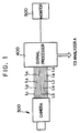
- the spectrum analysis system is constructed having a camera 300, a signal processor 400 and a monitor 500.
- the CCD (charge-coupled device) photosensor section of the camera 300 is shown on an enlarged scale in Fig. 2.
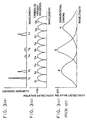
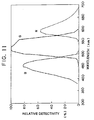
- the camera 300 has one photosensitive unit constituted by nine photosensors S1 ⁇ S9. As illustrated in Fig. 3(b), the detection wavelength ranges of the respective photosensors S1 ⁇ S9 do not overlap one another almost completely. On the other hand, in a case where the detection wavelength ranges of the nine photosensors S1 ⁇ S9 are collectively viewed, they cover substantially the whole visible radiation region. For comparison's sake, the outlines of the relative detectivity (or detection sensitivity) curves of a conventional camera are illustrated in Fig. 3(c). As seen by comparing the graphs of Figs.
- the detection wavelength ranges of the photosensors S1 ⁇ S3 lie near the detection wavelength range of a photosensor for blue light (B) in the conventional camera.
- the detection wavelength ranges of the photosensors S4 ⁇ S6 lie near the detection wavelength range of a photosensor for green light (G) in the conventional camera.
- the detection wavelength ranges of the photosensors S7 ⁇ S9 lie near the detection wavelength range of a photosensor for red light (R) in the conventional camera.
- the adjustments of such detection wavelength ranges can be made by altering the light transmission characteristics of a filter/filters which is/are disposed in the photosensor section.
- the light transmission characteristics can be altered by, for example, forming the plurality of stacked filters of the different characteristics or setting unequal film thicknesses or different compositions for the individual domains of the single filter.
- the camera 300 is furnished with output signal lines L1 ⁇ L9 which are provided in correspondence with the respective photosensors S1 ⁇ S9.
- the detection signals of the respective photosensors S1 ⁇ S9 can be delivered to the signal processor 400 independently of one another and every photosensitive unit. Needless to say, however, even when the output signal lines themselves are not independently led to the signal processor 400 in the number of nine, the signal components of the respective photosensors may be output in a separable state. Since the arrangements of circuits etc. for realizing such independent outputs are not, per se, especially restricted, they shall be omitted from description here.
- the signal processor 400 has such functions as synthesizing the output signals from the respective photosensors S1 ⁇ S9 and arithmetically processing them as required. Also, this processor 400 has the function of supplying the monitor 500 or any other analyzer A with the output signals of the camera 300 directly or after the synthesis or arithmetic processing thereof. By the way, “separation means” and “synthesis means” mentioned in the appended claims are implemented by the signal processor 400.
- the monitor 500 is an ordinary color monitor (or monochromatic monitor).
- a light component of wavelength ⁇ 1 is detected only by the photosensor S1.
- a light component of wavelength ⁇ 2 is detected only by the photosensor S2.
- light components of wavelengths ⁇ 4, ⁇ 5 and ⁇ 7 are respectively detected only by the photosensors S4, S5 and S7.
- the signal processor 400 supplies the analyzer A with only the signals of the photosensors for detecting the light components to-be-analyzed.
- the signal processor 400 delivers the detection signals of the photosensors S1 and S7.
- the detection signal of the photosensor S1 and that of the photosensor S7 are sent in the state in which they can be subjected to separation etc.
- the analyzer A obtains information on the light components of the desired wavelengths by analyzing the signals sent from the signal processor 400.
- the analisis method is not restricted in any way. In this case, strictly speaking, the emergent position of the light component detected by the photosensor S1 is different from that of the light component detected by the photosensor S7. Since, however, all the photosensors S1 ⁇ S9 are existent in close proximity, the signals detected by the respective photosensors may usually be handled as corresponding to the light components which have emerged from an identical position.
- the signal processor 400 executes the synthesis etc. of the output signals for the monitor 500 in parallel with the delivery of the output signals to the analyzer A.
- the synthesis serves to obtain the ordinary color picture. More specifically, the signal processor 400 synthesizes all the signals of the photosensors S1 ⁇ S3 and delivers the synthesized signal corresponding to a B (blue) signal produced by the conventional camera. Also, it synthesizes the signals of the photosensors S4 ⁇ S6 and delivers the synthesized signal corresponding to a G (green) signal produced by the conventional camera. Likewise, it synthesizes the signals of the photosensors S7 ⁇ S9 and delivers the synthesized signal corresponding to an R (red) signal produced by the conventional camera.
- a picture of more natural colors can be obtained by giving weights to the signals of the respective photosensors in the synthesis. Further, a more natural color picture can be obtained in such a way that, in synthesizing the signals which correspond to the G signal by way of example, not only the signals of the photosensors S4 ⁇ S6, but also those of the photosensors S2, S3, S7 and S8 for the peripheral wavelength regions of the detectivity ranges of the photosensors S4 ⁇ S6 are taken into consideration.
- the maximum sensitivities of all the photosensors S1 ⁇ S9 should preferably be equal. However, even when the maximum sensitivities are unequal, they can be corrected by signal processing.
- the overlaps of the detection wavelength ranges of the photosensors S1 ⁇ S9 should preferably be as small as possible in order to facilitate the synthesis processing and to analyze the spectrum more accurately.
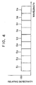
- the camera 300 has a detectivity curve as shown in Fig. 4, in which the detectivities or detection sensitivities of all the photosensors are flat and in which the valleys of the sensitivities between the respectively adjacent photosensors (parts where the sensitivities are low) are null.
- the reason therefor is that, in a case where the wavelength of the light component to be analyzed lies at the valley of the detectivity, the detectivity for the light component as required for the analysis becomes insufficient, so the spectrum analysis system is, in effect, inapplicable.
- one photosensitive unit is constituted by a larger number of photosensors. It is also considered, in principle, to handle the whole frame (namely, the whole imaging face of the camera 300) as one photosensitive unit under the condition that the detection wavelength ranges of any photosensors do not overlap. Since, in general, a CCD (charge-coupled device) includes several hundred thousand photosensors, the detection wavelength range of each of the photosensors becomes very narrow. Accordingly, it is also possible to perform spectrum analysis at a wavelength resolution which is equivalent to that of a spectroscope employing a prism and a diffraction grating.
- the camera thus constructed can be regarded as a camera in which a prism is included.
- a mechanical driver is not needed for the spectral separation of light as is in the case of the prism, and the whole wavelength range can be measured at the same time. Therefore, the construction is especially effective from the aspects of a quick measurement, a high shock resistance and a miniaturized equipment.
- the transmission characteristics of such minute regions can be respectively made different, as stated before by forming photosensor section with the stacked or multilayer filters, or by altering the film thickness or constituent material composition of the single filter for the individual domains thereof.
- the R, G and B signals are created by synthesizing the signals of the photosensors S1 ⁇ S9.
- photosensors dedicated to the color picture may well be disposed without such synthesis.
- those S11, S12 and S13 are respectively endowed with the same detectivity curves as in the conventional camera.
- the detection wavelength ranges of the other photosensors S14 ⁇ S19 are prevented from overlapping one another to the utmost, from the same viewpoint as in Fig. 3(b).
- the output signals of the photosensors S11, S12 and S13 can be respectively handled as the R, G and B signals to obtain a more natural color picture.
- the signals of the photosensors S14 ⁇ S19 are used for the analysis of light. According to this example, the obtainment of the more natural color picture and the accurate measurement of the light are made compatible.
- the detection wavelength ranges of the photosensors S11 ⁇ S13 of one group overlap those of the other photosensors S14 ⁇ S19 of the other group. Needless to say, however, no problem is posed because the signals of both the groups are separately utilized in accordance with the respective purposes (the generation of the color picture, and the spectrum analysis).
- the structure can be applied to monocolor camera or monocoler image.
- the spectrum analysis system of this embodiment can offer both the spectral detection of high precision and the obtainment of the ordinary color picture equivalent to vision with the naked eye (or a picture in a desired color tone).
- the narrower detection wavelength range is better.
- the extents or widths of the detection wavelength ranges of the respective photosensors need not be equal.
- the detection wavelength range of a corresponding photosensor S103 as illustrated in Fig. 7(a) may well be set wide in accordance with the extent of the wavelength range to-be-detected.
- the camera employed in the spectrum analysis system is applicable to all spectrum analyses.
- a camera 10 in an embodiment to be described below (a combustion system in Figs. 9 et seq.) is one form of application of the camera in the foregoing embodiment.
- the camera 10 has one photosensitive unit constituted by three sorts of photosensors like the conventional camera, the respective photosensors thereof have detection wavelength ranges which hardly overlap unlike those of the conventional camera.
- wavelengths at which the photosensors exhibit the maximum detectivities (450 [nm] for B and 510 [nm] for G) are respectively brought into substantial agreement with the central wavelengths of light components to-be-measured (the light emission of a CH radical at 431 [nm) and that of a C2 radical at 517 [nm]) (refer to Fig. 8(a)).
- a combustor 11 is furnished with a burner 50 which produces flames 100.
- the light emission picture of the flames 100 formed by the burner 50 is taken by the camera 10.
- This camera 10 is a so-called “electronic camera coping with R, G and B" which can deliver a red picture signal (R signal), a green picture signal (G signal) and a blue picture signal (B signal) both individually and independently as well as synthetically.
- the R, G and B camera signals i. e., the red picture signal (R signal), green picture signal (G signal) and blue picture signal (B signal) delivered from the camera 10 are synthesized, and the color picture of the flames 100 is delivered for monitoring to a conventional color monitor 40. Accordingly, the image of flames similar to the flames 100 observed by The naked eye is projected on the screen or the color monitor 40. At the same time, the color picture is stored in a picture memory 42 shown in Fig. 10, as an original picture which is not processed yet. It is accordingly possible to play back the picture at some other time.
- R signal red picture signal
- G signal green picture signal
- B signal blue picture signal
- the R, G and B camera signals produced by the camera 10 are sent to a picture accepting unit 20 and an arithmetic unit 21 in parallel with the delivery thereof to the color monitor 40, etc.
- the arithmetic unit 21 executes, e. g., air ratio calculation processing for evaluating a combustion state, by the use of the G and B signals.
- the air ratio calculation processing will be explained in detail later with reference to Fig. 13.
- the signals processed by the arithmetic unit 21 are led to a picture processor 22.
- the picture processor 22 executes pseudo color display processing, binarization processing for turning intensities into binary values with respect to any desired intensity, the calculations of areas and positions concerning a binarized picture, edge processing for connecting boundaries by lines, the calculations of the areas of regions enclosed with edges, the calculations of the lengths of the edges, the calculations of the average value and variance of the received light intensities of all pixels included in a measurement region, and so forth.
- Results obtained as the aforementioned feature quantities in relation to the input physical quantity picture are delivered to a comparison unit 24 and a unit 41 for monitoring a picture processing result.
- the monitor unit 41 for the picture processing result displays a result obtained through the pseudo color display processing of the physical quantity picture serving chiefly to evaluate the combustion state, though it may well display the processed result image explained before. Accordingly, the monitor unit 41 and the color monitor 40 project images concerning the identical flames 100, but the display picture of the former 41 becomes different from that of the latter 40 (refer to Fig. 10).
- a result processed by the picture accepting unit 20, arithmetic unit 21 and picture processor 22 is stored in a processed result memory 27 shown in Fig. 9 and can be utilized at some other time.
- the comparison unit 24 the feature quantity data of actual combustion flames actually received as an input are compared with the feature quantity data of ideal combustion flames stored in the memory 23 beforehand.
- control signals for bringing both the combustion flames into agreement within any desired limits are respectively delivered to a fuel rate controller 30 and an air rate controller 31.
- the fuel rate controller 30 alters the opening degree of a fuel rate control valve 33 for feeding fuel into the combustor 11
- the air rate controller 31 alters the opening degrees of air rate control valves 35, 36 for feeding air into the combustor 11.
- the air rate controller 31 increases the rate of the air to-be-fed.
- the optimum combustion state can be maintained at all times.
- This embodiment has the construction for detecting the combustion state (that is, the camera 10, the arithmetic unit 21, etc.), as the most important feature thereof. Accordingly, the ensuing description shall be centered on the featuring point.
- the camera 10 in this embodiment is the so-called "electronic camera coping with R, G and B" which can deliver the red picture signal (R signal), the green picture signal (G signal) and the blue picture signal (B signal) both individually and independently as well as synthetically.
- the relative detectivity of the camera 10 has the maximum sensitivities at 450 [nm] for blue (B), at 510 [nm] for green (G) and at 600 [nm] for red (R). Accordingly, as understood by superposing the relative detectivity on the light emission spectrum of flames depicted in Fig.
- a picture obtained as the blue picture signal (B signal) when the flames are photographed by the camera 10 corresponds mainly to the light of the CH radical
- a picture obtained as the green picture signal (G signal) corresponds mainly to the light of the C2 radical.
- Each of the detection sensitivities is not very narrow, but somewhat wide. Accordingly, the photosensor for detecting blue by way of example has characteristics adapted to detect, not only the light component of the wavelength 450 [nm], but also light components near this wavelength to some extent. However, those components of the light of the flames which are other than the wavelengths shown in Fig. 11 are feeble and do not pose any problem in the analysis.
- the camera 10 in this embodiment can detect light over the whole visible radiation region.
- the "air ratio" is defined as Q r /Q t .
- Q r denotes the quantity of air which has been really or actually fed in order to burn a certain quantity of fuel fed.
- Q t denotes the theoretical quantity of air which is required for the perfect combustion of the certain quantity of fuel fed.
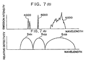
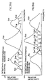
- Fig. 12 Shown in Fig. 12 are those examples of the light emission spectrum of the flames (100 in Fig. 9) which were measured under different air ratio conditions.
- the air ratio condition #1 corresponds to a case where the air is excessive, and the air ratio condition #2 a case where the air is insufficient.
- the intense emission light components of OH, CH and C2 radicals being intermediate reaction products OH radical: 310 [nm], CH radical: 431 [nm] and C2 radical: 517 [nm]
- the intensities of the emission light components change in accordance with the air ratio conditions. Accordingly, when the relationship of the air ratio with the emission intensity of each radical is investigated beforehand, the air ratio can be known from the emission intensity of the radical (refere to Fig. 8 (b)).
- the measurement of the emission intensity of only one radical is sometimes incapable of distinguishing a low measured intensity value from the lowering of the emission intensity attributed to the dirt of a window or peep hole for observing the flames.
- the influence of the dirty window can be canceled by evaluating the ratio between the emission intensities of the respective radicals. Results obtained by investigating the relationships between the ratios of the emission intensities of the respective radicals and the air ratio are illustrated in Fig. 13.
- the air ratio of the flames can be made known by finding the emission intensity ratio.
- the OH radical emits ultraviolet radiation, which usually attenuates in commercially-available optical components which are made from glass materials other than quartz glass.
- the light emissions of the CH radical and the C2 radical lying within the visible radiation region are utilized as light components which are easy to handle, in other words, that the air ratio is evaluated by measuring the intensities of the light components of 431 (nm] and 517 [nm].
- the ratio between the emission intensities of the CH and C2 radicals can be found by measuring the detection intensity ratio between the blue picture signal (B signal) and the green picture signal (G signal) which are delivered from the camera (10 in Figs. 9 and 10).
- B signal blue picture signal
- G signal green picture signal
- the intensity ratio is calculated for every photosensitive unit (that is, between a blue pixel and a green pixel which belong to the identical photosensitive unit (i, j) on the frame of the image or the imaging face of the camera) and over the whole frame (or in a desired region)
- an air ratio distribution picture can be obtained (refer to Figs. 14(a), 14(b) and 14(c)).
- the single camera can be used for monitoring the flames on the basis of the ordinary color picture and for obtaining the picture indicative of the distribution of the air ratio values.
- the air ratio distribution picture can be obtained in a short time period, and it has a high accuracy.
- the system can be operated with ease. It is accordingly possible to provide the combustion system which can control the fuel and air rates more precisely, which is favorable for the protection of the environment and which has a high combustion efficiency.
- the single camera since the single camera is included, a camera focusing operation is easy.
- the camera 10 in this embodiment is directly and extensively usable for measuring the combustion states of flames.
- the camera 10 is applicable to various kinds of liquid fuel and gaseous fuel such as natural gas and heavy oil.
- the reason therefor is that all of these kinds of fuel contain elements C, H etc. and involve the light emissions of the CH radical etc. in its flame part.
- solid fuel such as coal emits radiant heat besides the radical emission light during its combustion. Therefore, another countermeasures are needed for the camera to be applicable.
- the camera 10 can be used for the evaluation of all the other combustion states by altering the sensitivity curves of the photosensors thereof.
- the combustion system of this embodiment features that the combustion properties of a plurality of burners are evaluated and controlled on the basis of a single camera.
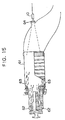
- a combustor 61 in the combustion system is illustrated in Fig. 15.
- the constituents of this embodiment not shown in the figure for example, the color monitor 40, the arithmetic unit 21 and the monitor 41
- the constituents of this embodiment not shown in the figure are fundamentally the same as in the preceding embodiment illustrated in Figs. 9 and 10.
- the combustor 61 is a gas turbine combustor, which includes a group of inner burners 62 and a group of outer burners 63.
- a gas turbine combustor which includes a group of inner burners 62 and a group of outer burners 63.
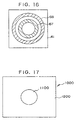
- an air ratio distribution picture is displayed on the screen of the monitor unit 41, and the whole air ratio distributions of flames zones formed by the group of inner burners 62 and the group of outer burners 63 can be simultaneously measured. Accordingly, this embodiment has the effect that the combustion states of the plurality of burners can be evaluated and managed at the same time. It is desirable that the flames zone 67 formed by the group of burners 62 and the flames zone 68 formed by the group of burners 63 have uniform air ratios as illustrated in Fig. 16, respectively.
- the air ratio distribution of at least either of the flames zones 67 and 68 becomes nonuniform for some reason.
- judgement is passed using the data of a region where the flames zone 67 is projected on the monitor screen (refer to Fig. 16).
- judgement is passed in view of only a region where the flames zone 68 is projected on the monitor screen (refer to Fig. 16).
- the adjustments of a fuel rate and an air rate, etc. can be done in order to eliminate the nonuniformity in the air ratio distribution.
- a portion to be remodeled is revealed.
- the uniform combustion of the flames leads to an enhanced combustion efficiency, and can decrease the p.p.m. (parts per million) of nitrogen oxides in an exhaust gas. Therefore, the measurement of the air ratio distributions is very effective.
- the photosensors may well be endowed with different sensitivity or detectivity characteristics in accordance with the positions of the CCD section on the imaging face of the camera.
- the photosensors may well be endowed with different sensitivity or detectivity characteristics in accordance with the positions of the CCD section on the imaging face of the camera.
- the sensitivity characteristics of the photosensors S24 ⁇ S29 and those S'24 ⁇ S'29 which are used for the spectrum analysis are made different between the central region 1100 of the imaging face 1000 for mainly projecting the inner burners 62 and in the peripheral region 1200 thereof for mainly projecting the outer burners 63.
- the sensitivity characteristics of the photosensorS S24 ⁇ S29 of the central region 1100 are suited to observe the light of the inner burners 62.
- the sensitivity characteristics of the photosensors S'24 ⁇ S'29 of the peripheral region 1200 are suited to observe the light of the outer burners 63.
- the photosensorS S21 ⁇ S23 for obtaining the color pictured however, are kept having the same characteristics as those of the conventional camera in both the central region 1100 and the peripheral region 1200.
- a more precise spectrum analysis is realized in spite of the use of a CCD (charge-coupled device) which includes the small number of photosensors.
- the CCD having the small number of photosensors is usually inexpensive, the cost of the apparatus can be curtailed further.
- the "plasma chemical process” is a process in which a radical entailing light emission is used for a reaction so as to synthesize a substance, and in which the distributed state of the light emitting radical affects the behaviors of the product greatly. It is accordingly necessary to control the internal pressure of a process chamber, the feed rates of starting materials, etc. while the distributed state of the radical is being normally monitored. In the present situation, however, the intensity distribution of the radical light emission is seldom monitored, and the finished product is merely inspected in most cases. Therefore, rejected behaviors are presently exhibited at a high rate.
- the "conventional camera” termed here signifies the camera whose detection wavelength ranges of R, G and B overlap one another and cover the whole visible radiation region as illustrated in Fig. 3(c).
- the spectrometric camera of the present invention and the spectrum analysis system employing it are applicable without being attended with such problems. Accordingly, the intensity distributions of the radical light emissions can be normally monitored, and the quality of the product can be enhanced.
- each of the embodiments of the combustion systems has been described as including the separate monitors for the color picture and for the spectrum analysis, a single television monitor may well be used. Even in this case, both the functions can be switched merely by altering the contents of signal processing within the apparatus (or the choices of signals to be delivered to the monitor), and hence, faults are hardly liable to occur. In addition, the system is easy of handling.
- the present invention is also applicable to any other camera which detects light on the basis of another principle or another method, as long as the camera can be endowed with different detection wavelength ranges at the respective parts (respective pixels) of the imaging face thereof.
- the present invention is especially effective as stated below.
- both the creation of a color picture close to the sight of man and a spectrum analysis based on the extraction of only the light of each specified wavelength can be performed using a single camera. This is advantageous in point of cost. Moreover, since filters etc. mounted outside a camera are not used for separating the light components of the respective wavelengths, the spectrum analysis system undergoes infrequent faults and can be handled similarly to a system employing the conventional camera(s).
- the spectrum analysis system of the present invention When the spectrum analysis system of the present invention is applied to, for example, a combustion evaluation apparatus, both the creation of the color picture and the observation of flames based on air ratios can be performed. Besides, the combustion properties of the flames can be evaluated in spatial relations in a short time through only the simple optical adjustments of focusing. Accordingly, the flames can be correctly diagnosed, and the accuracy of a combustion control is enhanced. Further, a combustion system which is favorable for the protection of environment and which has a high combustion efficiency can be provided by applying the apparatus or method.
Landscapes
- Engineering & Computer Science (AREA)
- Physics & Mathematics (AREA)
- Spectroscopy & Molecular Physics (AREA)
- Chemical & Material Sciences (AREA)
- Combustion & Propulsion (AREA)
- Mechanical Engineering (AREA)
- General Engineering & Computer Science (AREA)
- General Physics & Mathematics (AREA)
- Control Of Combustion (AREA)
- Spectrometry And Color Measurement (AREA)
- Investigating Or Analysing Materials By Optical Means (AREA)
Abstract
Description
- The present invention relates to a camera which can deliver both an ordinary color picture and spectrum analyzing data, a spectrum analysis system, and a combustion evaluation apparatus which employs them.
- In a case where a camera employing a CCD (charge-coupled device) or the like is applied to spectrum analysis, only light of a desired wavelength is measured by externally mounting a filter on the camera. Besides, in the case of analyzing a spectrum over a plurality of wavelengths, or in case of requiring an ordinary color picture, a plurality of filters and cameras are used.
- Mentioned as an example in which the camera is actually used for the spectrum analysis in this manner is a video system for analyzing the spectrum of flames in a gas turbine combustor as disclosed in Japanese Patent Application Laid-open No. 207912/1991.
- The prior art, however, is problematic as stated below. In the case of changing-over the plurality of filters in use, a mechanism for driving the filters is necessitated which incurs the problem of a complicated structure.
- It is also considered to install separate cameras for the respective filters. In this case, however, the operations of determining positions and angles for photographing, focusing the cameras, etc. must be performed in correspondence with the number of cameras for use. This poses the problem that a rapid measurement is impossible. Especially in the spectrum analysis, all the cameras need to be focused on an identical location, resulting in very difficult handling.
- Another problem is that the system becomes costly.
- The present invention has for its object to provide a camera which can, by itself, deliver an ordinary color picture and simultaneously deliver information for spectrum analysis, and a spectrum analysis system which employs the camera.
- Another object of the present invention is to provide a combustion evaluation apparatus which employs the camera and the spectrum analysis system specified above.
- In the first aspect of performance of the present invention for accomplishing such objects, there is provided a camera comprising a plurality of photosensors which are disposed on an imaging face thereof, and which separatly deliver photodetection signals of each of the photosensors; at least two of the plurality of photosensors in a predetermined combination being set as one photosensitive unit on a condition that the photosensors included in the one photosensitive unit have detection wavelength ranges which do not overlap each other.
- Preferably, the photosensors constituting the one photosensitive unit are arranged in adjacency to each other on the imaging face.
- It is also preferable that a comprehensive detection wavelength range of all the photosensors constituting the one photosensitive unit covers the whole visible radiation range.
- In a camera for observing light of certain specified wavelength, a photosensor which has a maximum detectivity at and near the specified wavelength should preferably be included in each of the photosensitive units.
- It is preferable that at least one member selected from the group consisting of emission wavelengths of a CH radical, a C₂ radical and an OH radical is contained as the specified wavelength.
- In the second aspect of performance of the present invention, there is provided a spectrum analysis system comprising the camera defined in the first aspect of performance; and separation means for separating only the signals of the desired photosensors from an output signal of the camera.
- In the third aspect of performance of the present invention, there is provided a spectrum analysis system comprising the camera defined in the first aspect of performance; and synthesis means for synthesizing R (red), G (green) and B (blue) signals using an output signal from the camera.
- In the fourth aspect of performance of the present invention, there is provided a camera comprising a plurality of photosensors which are disposed on an imaging face thereof, and which separatly deliver photodetection signals of each of the photosensors; the photosensors including at least one member selected from the group consisting of a first photosensor whose detection wavelength range contains an emission wavelength of a CH radical, but does not contain emission wavelengths of either a C₂ radical or an OH radical; a second photosensor whose detection wavelength range contains the emission wavelength of the C₂ radical, but does not contain the emission wavelengths of either the CH radical or the OH radical; and a third photosensor whose detection wavelength range contains the emission wavelength of the OH radical, but does not contain the emission wavelengths of either the CH radical or the C₂ radical.
- In the fifth aspect of performance of the present invention, there is provided a camera comprising a plurality of photosensors which are disposed on an imaging face thereof, and which separately deliver photodetection signals of each of the photosensors; at least two adjacent ones of the plurality of photosensors being set as one photosensitive unit; the one photosensitive unit including at least two members selected from the group consisting of a first photosensor whose detection wavelength range contains an emission wavelength of a CH radical, but does not contain emission wavelengths of either a C₂ radical or an OH radical; a second photosensor whose detection wavelength range contains the emission wavelength of the C₂ radical, but does not contain the emission wavelengths of either the CH radical or the OH radical; and a third photosensor whose detection wavelength range contains the emission wavelength of the OH radical, but does not contain the emission wavelengths of either the CH radical or the C₂ radical.
- In the sixth aspect of performance of the present invention, there is provided a spectrum analysis system comprising the camera defined in the fourth aspect of performance; and separation means for separating only the signals of the desired photosensors from an output signal of the camera.
- In the seventh aspect of performance of the present invention, there is provided a spectrum analysis system comprising the camera defined in the fourth aspect of performance; and synthesis means for synthesizing R (red), G (green) and B (blue) signals using an output signal from the camera.
- In the eighth aspect of performance of the present invention, there is provided a camera comprising a plurality of photosensors, which separately deliver photodetection signals of each of the photosensors; at least two adjacent ones of the plurality of photosensors being set as one photosensitive unit; the one photosensitive unit including photosensors for a color picture which exhibit sensitivity curves agreeing with those of ordinary color television, and photosensors for spectrum analysis whose detection wavelength ranges do not overlap one another.
- In the ninth aspect of performance of the present invention, there is provided a spectrum analysis system comprising the camera defined in the eighth aspect of performance; and separation means for separating only the signals of the desired photosensors among the output signals derived from the photosensors for the spectrum analysis.
- In the tenth aspect of performance of the present invention, there is provided a combustion evaluation apparatus for evaluating a combustion state of flames, comprising a camera which photographs the flames; display means for displaying a picture of the frames by using an output signal from the camera; and arithmetic means for obtaining a physical quantity for evaluating a combustion property of the flames, using the output signal from the camera.
- In the eleventh aspect of performance of the present invention, there is provided a combustion system comprising a burner which burns a mixture consisting of fuel and air; feed means for feeding the fuel and the air to the burner; adjustment means for adjusting a feed rate of at least one of the fuel and the air which are to be fed to the burner; a camera which photographs flames; display means for displaying a picture of the frames by using an output signal from the camera; arithmetic means for obtaining a physical quantity for evaluating a combustion property of the flames, by using the output signal from the camera; and control means for controlling the adjustment means in accordance with the physical quantity obtained by the arithmetic means.
- The first thru third aspects of performance correspond to
Claims 1 thru 7, and will be explained below from operational viewpoints. - The output signals of the respective photosensors are separated by the separation means, whereby the intensities of light components in the certain detection wavelength ranges can be detected. On the other hand, the output signals of the respective photosensors are synthesized by the synthesis means, whereby the ordinary color picture can be obtained.
- In the case of an application to the evaluation of the combustion state of flames, the emission intensity of the radical of an intermediate reaction product attendant upon combustion can be detected by setting at least one of 310 [nm], 431 [nm] and 517 (nm] as the specified wavelength.
- The fourth thru seventh aspects of performance corresponding to
Claims 8 thru 11 will be explained. - The first thru third photosensors each detect only the emissions of the specified radicals, and they do not detect the emission of any other radical. Accordingly, when the photosensors of at least one of the three sorts are included, the combustion state of flames can be determined. Further, when the photosensors of at least two of the three sorts are included, the photodetection signals of the camera can be used for such processing as taking the ratio between both the signals.
- The eighth and ninth aspects of performance corresponding to
Claims - The ordinary color picture can be obtained by using the output signals from the photosensors for the color picture. On the other hand, information items in the desired detection wavelength ranges can be obtained in such a way that the output signals of the photosensors for the spectrum analysis are separated by the separation means.
- The tenth and eleventh aspects of performance corresponding to Claims 14 thru 16 will be explained.
- It is permitted to monitor the combustion state on the basis of the picture of the flames displayed on the display means and to evaluate the combustion state by using the physical quantity calculated by the arithmetic means. Further, the control means controls the adjustment means by using the physical quantity. Thus, the feed rate/rates of the fuel and/or the air based on the feed means can be precisely adjusted.
-
- Fig. 1 is a block diagram showing the general construction of a spectrum analysis system according to the present invention;
- Fig. 2 is a schematic diagram showing photosensors which constitute one photosensitive unit in the CCD (charge-coupled device) section of a camera according to the present invention;
- Figs. 3(a) thru 3(c) are graphs for explaining the relative detectivities of the camera of the present invention and a conventional camera;
- Fig. 4 is a graph showing the ideal relative detectivity of the camera in the case where the camera of the present invention is made versatile;
- Fig. 5 is a graph showing an example of the relative detectivity of the camera in the case where photosensors for a color picture and photosensors for spectrum analysis are disposed completely separately;
- Fig. 6 is a graph showing another example of the relative detectivity of the camera in the case where photosensors for a color picture and photosensors for a spectrum analysis are disposed completely separately;
- Figs. 7(a) and 7(b) are graphical illustrations showing an example of the relative detectivity of the camera in the case where the detection wavelength ranges of photosensors are changed;
- Fig. 8(a) is a graphical illustration showing a situation in the case where the spectrometric camera of the present invention is applied to a combustion system;
- Fig. 8(b) is agraphical illustration showing a relationship between emission intensity ratio and air ratio.
- Fig. 9 is a schematic block diagram showing the general construction of the combustion system in an embodiment of the present invention;
- Fig. 10 is an explanatory diagram showing a light receiving system;
- Fig. 11 is a graph showing the relative detectivity of the camera in the embodiment;
- Fig. 12 is a graph showing the emission spectrum of flames;
- Fig. 13 is a graph showing the relationships of emission intensity ratios and air ratios among radicals;
- Figs. 14(a), 14(b) and 14(c) are diagrams for explaining a method of obtaining an air ratio distribution picture;
- Fig. 15 is a side view, partly in section, showing the combustion system in another embodiment of the present invention;
- Fig. 16 is a diagram showing a monitor screen on which a picture taken for the example of Fig. 15 is displayed;
- Fig. 17 is a diagram for explaining an example in which the detectivity characteristics of photosensors are changed for the respective regions of an imaging face in accordance with an object to-be-measured; and
- Figs. 18(a) and 18(b) are graphical illustrations exemplifying relative detectivity characteristics in the case of Fig. 17.
- A spectrum analysis system embodying the present invention will be described.
- The spectrum analysis system in this embodiment features that a single camera can be used for observing the light component(s) of desired wavelength(s) and simultaneously for obtaining an ordinary color picture.
- As illustrated in Fig. 1, the spectrum analysis system is constructed having a
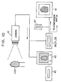
camera 300, asignal processor 400 and amonitor 500. - The CCD (charge-coupled device) photosensor section of the
camera 300 is shown on an enlarged scale in Fig. 2. Thecamera 300 has one photosensitive unit constituted by nine photosensors S₁ ∼ S₉. As illustrated in Fig. 3(b), the detection wavelength ranges of the respective photosensors S₁ ∼ S₉ do not overlap one another almost completely. On the other hand, in a case where the detection wavelength ranges of the nine photosensors S₁ ∼ S₉ are collectively viewed, they cover substantially the whole visible radiation region. For comparison's sake, the outlines of the relative detectivity (or detection sensitivity) curves of a conventional camera are illustrated in Fig. 3(c). As seen by comparing the graphs of Figs. 3(b) and 3(c), the detection wavelength ranges of the photosensors S₁ ∼ S₃ lie near the detection wavelength range of a photosensor for blue light (B) in the conventional camera. In addition, the detection wavelength ranges of the photosensors S₄ ∼ S₆ lie near the detection wavelength range of a photosensor for green light (G) in the conventional camera. Besides, the detection wavelength ranges of the photosensors S₇ ∼ S₉ lie near the detection wavelength range of a photosensor for red light (R) in the conventional camera. The adjustments of such detection wavelength ranges can be made by altering the light transmission characteristics of a filter/filters which is/are disposed in the photosensor section. The light transmission characteristics can be altered by, for example, forming the plurality of stacked filters of the different characteristics or setting unequal film thicknesses or different compositions for the individual domains of the single filter. - Referring back to Fig. 1, the
camera 300 is furnished with output signal lines L₁ ∼ L₉ which are provided in correspondence with the respective photosensors S₁ ∼ S₉. Thus, the detection signals of the respective photosensors S₁ ∼ S₉ can be delivered to thesignal processor 400 independently of one another and every photosensitive unit. Needless to say, however, even when the output signal lines themselves are not independently led to thesignal processor 400 in the number of nine, the signal components of the respective photosensors may be output in a separable state. Since the arrangements of circuits etc. for realizing such independent outputs are not, per se, especially restricted, they shall be omitted from description here. - The
signal processor 400 has such functions as synthesizing the output signals from the respective photosensors S₁ ∼ S₉ and arithmetically processing them as required. Also, thisprocessor 400 has the function of supplying themonitor 500 or any other analyzer A with the output signals of thecamera 300 directly or after the synthesis or arithmetic processing thereof. By the way, "separation means" and "synthesis means" mentioned in the appended claims are implemented by thesignal processor 400. - The
monitor 500 is an ordinary color monitor (or monochromatic monitor). - Next, let's consider a case where light having a spectral distribution shown in Fig. 3(a) is observed by the use of the spectrum analysis system.
- A light component of wavelength λ₁ is detected only by the photosensor S₁. Besides, a light component of wavelength λ₂ is detected only by the photosensor S₂. Likewise, light components of wavelengths λ₄, λ₅ and λ₇ are respectively detected only by the photosensors S₄, S₅ and S₇. The
signal processor 400 supplies the analyzer A with only the signals of the photosensors for detecting the light components to-be-analyzed. By way of example, in the case of analyzing the light components of the wavelengths λ₁ and λ₇, thesignal processor 400 delivers the detection signals of the photosensors S₁ and S₇. Of course, also in this case, the detection signal of the photosensor S₁ and that of the photosensor S₇ are sent in the state in which they can be subjected to separation etc. - The analyzer A obtains information on the light components of the desired wavelengths by analyzing the signals sent from the
signal processor 400. Incidentally, the analisis method is not restricted in any way. In this case, strictly speaking, the emergent position of the light component detected by the photosensor S₁ is different from that of the light component detected by the photosensor S₇. Since, however, all the photosensors S₁ ∼ S₉ are existent in close proximity, the signals detected by the respective photosensors may usually be handled as corresponding to the light components which have emerged from an identical position. - On the other hand, the
signal processor 400 executes the synthesis etc. of the output signals for themonitor 500 in parallel with the delivery of the output signals to the analyzer A. The synthesis serves to obtain the ordinary color picture. More specifically, thesignal processor 400 synthesizes all the signals of the photosensors S₁ ∼ S₃ and delivers the synthesized signal corresponding to a B (blue) signal produced by the conventional camera. Also, it synthesizes the signals of the photosensors S₄ ∼ S₆ and delivers the synthesized signal corresponding to a G (green) signal produced by the conventional camera. Likewise, it synthesizes the signals of the photosensors S₇ ∼ S₉ and delivers the synthesized signal corresponding to an R (red) signal produced by the conventional camera. It is needless to say that, on this occasion, a picture of more natural colors can be obtained by giving weights to the signals of the respective photosensors in the synthesis. Further, a more natural color picture can be obtained in such a way that, in synthesizing the signals which correspond to the G signal by way of example, not only the signals of the photosensors S₄ ∼ S₆, but also those of the photosensors S₂, S₃, S₇ and S₈ for the peripheral wavelength regions of the detectivity ranges of the photosensors S₄ ∼ S₆ are taken into consideration. - The maximum sensitivities of all the photosensors S₁ ∼ S₉ should preferably be equal. However, even when the maximum sensitivities are unequal, they can be corrected by signal processing. The overlaps of the detection wavelength ranges of the photosensors S₁ ∼ S₉ should preferably be as small as possible in order to facilitate the synthesis processing and to analyze the spectrum more accurately.
- It is preferable for rendering the spectrum analysis system more versatile that the
camera 300 has a detectivity curve as shown in Fig. 4, in which the detectivities or detection sensitivities of all the photosensors are flat and in which the valleys of the sensitivities between the respectively adjacent photosensors (parts where the sensitivities are low) are null. The reason therefor is that, in a case where the wavelength of the light component to be analyzed lies at the valley of the detectivity, the detectivity for the light component as required for the analysis becomes insufficient, so the spectrum analysis system is, in effect, inapplicable. On the other hand, for constructing a system which is dedicated to a specified use, it is preferable that the curves of the detectivities of the individual photosensors form crests and that the wavelength of the maximum detectivity is held in agreement with the wavelength of the desired light component (refer to Figs. 3(a) and 3(b)). Needless to say, this is intended to detect the desired light component sensitively and to simultaneously minimize the detections of light components irrelevant to the analysis. - In general, narrowing the detection wavelength ranges of the individual photosensors realizes a measurement of higher versatility and higher precision. In this case, one photosensitive unit is constituted by a larger number of photosensors. It is also considered, in principle, to handle the whole frame (namely, the whole imaging face of the camera 300) as one photosensitive unit under the condition that the detection wavelength ranges of any photosensors do not overlap. Since, in general, a CCD (charge-coupled device) includes several hundred thousand photosensors, the detection wavelength range of each of the photosensors becomes very narrow. Accordingly, it is also possible to perform spectrum analysis at a wavelength resolution which is equivalent to that of a spectroscope employing a prism and a diffraction grating. The camera thus constructed can be regarded as a camera in which a prism is included. In this case, a mechanical driver is not needed for the spectral separation of light as is in the case of the prism, and the whole wavelength range can be measured at the same time. Therefore, the construction is especially effective from the aspects of a quick measurement, a high shock resistance and a miniaturized equipment. The transmission characteristics of such minute regions can be respectively made different, as stated before by forming photosensor section with the stacked or multilayer filters, or by altering the film thickness or constituent material composition of the single filter for the individual domains thereof.
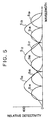
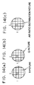
- According to the above embodiment, in obtaining the ordinary color picture, the R, G and B signals are created by synthesizing the signals of the photosensors S₁ ∼ S₉. However, photosensors dedicated to the color picture may well be disposed without such synthesis. By way of example, as illustrated in Fig. 5, among photosensors S₁₁ ∼ S₁₉ which constitute one photosensitive unit, those S₁₁, S₁₂ and S₁₃ are respectively endowed with the same detectivity curves as in the conventional camera. The detection wavelength ranges of the other photosensors S₁₄ ∼ S₁₉ are prevented from overlapping one another to the utmost, from the same viewpoint as in Fig. 3(b). Thus, the output signals of the photosensors S₁₁, S₁₂ and S₁₃ can be respectively handled as the R, G and B signals to obtain a more natural color picture. On the other hand, the signals of the photosensors S₁₄ ∼ S₁₉ are used for the analysis of light. According to this example, the obtainment of the more natural color picture and the accurate measurement of the light are made compatible. Herein, the detection wavelength ranges of the photosensors S₁₁ ∼ S₁₃ of one group overlap those of the other photosensors S₁₄ ∼ S₁₉ of the other group. Needless to say, however, no problem is posed because the signals of both the groups are separately utilized in accordance with the respective purposes (the generation of the color picture, and the spectrum analysis). The structure can be applied to monocolor camera or monocoler image.
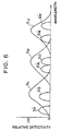
- Although, in the example of Fig. 5, no valleys of sensitivity are formed over the whole detection wavelength range of the photosensors S₁₄ ∼ S₁₉ for the spectrum analysis, this measure is not always required in such a case where the wavelengths of light to be observed are specified beforehand. Since the photosensors for the spectrum analysis do not have their output signals utilized for the generation of the color picture, they may well be endowed with sensitivities only to necessary wavelength ranges just as photosensors S'₁₄ ∼ S'₁₉ illustrated in Fig. 6.
- As thus far described, the spectrum analysis system of this embodiment can offer both the spectral detection of high precision and the obtainment of the ordinary color picture equivalent to vision with the naked eye (or a picture in a desired color tone).
- It has been stated in the above that, in general, the measurement becomes more precise as the detection wavelength ranges of the photosensors are made narrower. However, in a case where a light component to be detected has a wide wavelength range, it does not hold true that the narrower detection wavelength range is better. Besides, the extents or widths of the detection wavelength ranges of the respective photosensors need not be equal. By way of example, in the case of a
light component 6000 which has a comparatively extensive range of wavelengths as illustrated in Fig. 7(b), the detection wavelength range of a corresponding photosensor S₁₀₃ as illustrated in Fig. 7(a) may well be set wide in accordance with the extent of the wavelength range to-be-detected. In contrast, regarding alight component 5000 whose wavelength range is hardly extensive, the detection wavelength range of a corresponding photosensor S₁₀₂ may well be narrowed. In this case, however, a color picture of natural colors cannot be obtained by synthesizing the signals of photosensors S₁₀₁ ∼ S₁₀₃. It is therefore favorable to adopt the technique illustrated in Fig. 5 or Fig. 6. - The camera employed in the spectrum analysis system is applicable to all spectrum analyses. By way of example, a
camera 10 in an embodiment to be described below (a combustion system in Figs. 9 et seq.) is one form of application of the camera in the foregoing embodiment. Although thecamera 10 has one photosensitive unit constituted by three sorts of photosensors like the conventional camera, the respective photosensors thereof have detection wavelength ranges which hardly overlap unlike those of the conventional camera. In addition, wavelengths at which the photosensors exhibit the maximum detectivities (450 [nm] for B and 510 [nm] for G) are respectively brought into substantial agreement with the central wavelengths of light components to-be-measured (the light emission of a CH radical at 431 [nm) and that of a C₂ radical at 517 [nm]) (refer to Fig. 8(a)). - There will now be described the embodiment in which the spectrum analyzing camera of the present invention is applied to the combustion system.
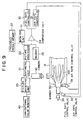
- The combustion system will be outlined with reference to Fig. 9.
- In the combustion system of this embodiment, a combustor 11 is furnished with a
burner 50 which producesflames 100. The light emission picture of theflames 100 formed by theburner 50 is taken by thecamera 10. Thiscamera 10 is a so-called "electronic camera coping with R, G and B" which can deliver a red picture signal (R signal), a green picture signal (G signal) and a blue picture signal (B signal) both individually and independently as well as synthetically. - The R, G and B camera signals, i. e., the red picture signal (R signal), green picture signal (G signal) and blue picture signal (B signal) delivered from the
camera 10 are synthesized, and the color picture of theflames 100 is delivered for monitoring to aconventional color monitor 40. Accordingly, the image of flames similar to theflames 100 observed by The naked eye is projected on the screen or thecolor monitor 40. At the same time, the color picture is stored in apicture memory 42 shown in Fig. 10, as an original picture which is not processed yet. It is accordingly possible to play back the picture at some other time. - Besides, the R, G and B camera signals produced by the
camera 10 are sent to apicture accepting unit 20 and anarithmetic unit 21 in parallel with the delivery thereof to thecolor monitor 40, etc. Thearithmetic unit 21 executes, e. g., air ratio calculation processing for evaluating a combustion state, by the use of the G and B signals. The air ratio calculation processing will be explained in detail later with reference to Fig. 13. - The signals processed by the
arithmetic unit 21 are led to apicture processor 22. As to a physical quantity picture for evaluating, for example, the combustion state, thepicture processor 22 executes pseudo color display processing, binarization processing for turning intensities into binary values with respect to any desired intensity, the calculations of areas and positions concerning a binarized picture, edge processing for connecting boundaries by lines, the calculations of the areas of regions enclosed with edges, the calculations of the lengths of the edges, the calculations of the average value and variance of the received light intensities of all pixels included in a measurement region, and so forth. Results obtained as the aforementioned feature quantities in relation to the input physical quantity picture are delivered to acomparison unit 24 and aunit 41 for monitoring a picture processing result. - The
monitor unit 41 for the picture processing result displays a result obtained through the pseudo color display processing of the physical quantity picture serving chiefly to evaluate the combustion state, though it may well display the processed result image explained before. Accordingly, themonitor unit 41 and the color monitor 40 project images concerning theidentical flames 100, but the display picture of the former 41 becomes different from that of the latter 40 (refer to Fig. 10). Incidentally, a result processed by thepicture accepting unit 20,arithmetic unit 21 andpicture processor 22 is stored in a processedresult memory 27 shown in Fig. 9 and can be utilized at some other time. - In the
comparison unit 24, the feature quantity data of actual combustion flames actually received as an input are compared with the feature quantity data of ideal combustion flames stored in thememory 23 beforehand. In a case where the difference between the actual combustion flames and the ideal combustion flames is great, control signals for bringing both the combustion flames into agreement within any desired limits are respectively delivered to afuel rate controller 30 and anair rate controller 31. In accordance with the corresponding control signals, thefuel rate controller 30 alters the opening degree of a fuelrate control valve 33 for feeding fuel into the combustor 11, and theair rate controller 31 alters the opening degrees of airrate control valves air rate controller 31 increases the rate of the air to-be-fed. Thus, the optimum combustion state can be maintained at all times. - This embodiment has the construction for detecting the combustion state (that is, the
camera 10, thearithmetic unit 21, etc.), as the most important feature thereof. Accordingly, the ensuing description shall be centered on the featuring point. - The
camera 10 in this embodiment is the so-called "electronic camera coping with R, G and B" which can deliver the red picture signal (R signal), the green picture signal (G signal) and the blue picture signal (B signal) both individually and independently as well as synthetically. As illustrated in Fig. 11, the relative detectivity of thecamera 10 has the maximum sensitivities at 450 [nm] for blue (B), at 510 [nm] for green (G) and at 600 [nm] for red (R). Accordingly, as understood by superposing the relative detectivity on the light emission spectrum of flames depicted in Fig. 12, a picture obtained as the blue picture signal (B signal) when the flames are photographed by thecamera 10 corresponds mainly to the light of the CH radical, and a picture obtained as the green picture signal (G signal) corresponds mainly to the light of the C₂ radical. Each of the detection sensitivities is not very narrow, but somewhat wide. Accordingly, the photosensor for detecting blue by way of example has characteristics adapted to detect, not only the light component of the wavelength 450 [nm], but also light components near this wavelength to some extent. However, those components of the light of the flames which are other than the wavelengths shown in Fig. 11 are feeble and do not pose any problem in the analysis. - Further, when viewed as the whole photosensor section, the
camera 10 in this embodiment can detect light over the whole visible radiation region. - Next, there will be explained the principles of that calculation of the air ratio of flames which is executed by the
arithmetic unit 21. - The "air ratio" is defined as Qr/Qt. Here, the symbol Qr denotes the quantity of air which has been really or actually fed in order to burn a certain quantity of fuel fed. On the other hand, the symbol Qt denotes the theoretical quantity of air which is required for the perfect combustion of the certain quantity of fuel fed.
- Shown in Fig. 12 are those examples of the light emission spectrum of the flames (100 in Fig. 9) which were measured under different air ratio conditions. In the graph of Fig. 12, the air
ratio condition # 1 corresponds to a case where the air is excessive, and the air ratio condition #2 a case where the air is insufficient. It is understood from the graph that the intense emission light components of OH, CH and C₂ radicals being intermediate reaction products (OH radical: 310 [nm], CH radical: 431 [nm] and C₂ radical: 517 [nm]) are observed, and that the intensities of the emission light components change in accordance with the air ratio conditions. Accordingly, when the relationship of the air ratio with the emission intensity of each radical is investigated beforehand, the air ratio can be known from the emission intensity of the radical (refere to Fig. 8 (b)). - In this case, the measurement of the emission intensity of only one radical is sometimes incapable of distinguishing a low measured intensity value from the lowering of the emission intensity attributed to the dirt of a window or peep hole for observing the flames. The influence of the dirty window can be canceled by evaluating the ratio between the emission intensities of the respective radicals. Results obtained by investigating the relationships between the ratios of the emission intensities of the respective radicals and the air ratio are illustrated in Fig. 13. As is obvious from the graph of the figure, the air ratio of the flames can be made known by finding the emission intensity ratio. Incidentally, the OH radical emits ultraviolet radiation, which usually attenuates in commercially-available optical components which are made from glass materials other than quartz glass.
- It is therefore practical that the light emissions of the CH radical and the C₂ radical lying within the visible radiation region are utilized as light components which are easy to handle, in other words, that the air ratio is evaluated by measuring the intensities of the light components of 431 (nm] and 517 [nm].
- In the actual determination of the air ratio, the ratio between the emission intensities of the CH and C₂ radicals can be found by measuring the detection intensity ratio between the blue picture signal (B signal) and the green picture signal (G signal) which are delivered from the camera (10 in Figs. 9 and 10). When the intensity ratio is calculated for every photosensitive unit (that is, between a blue pixel and a green pixel which belong to the identical photosensitive unit (i, j) on the frame of the image or the imaging face of the camera) and over the whole frame (or in a desired region), an air ratio distribution picture can be obtained (refer to Figs. 14(a), 14(b) and 14(c)).
- As stated above, according to the combustion system of this embodiment, the single camera can be used for monitoring the flames on the basis of the ordinary color picture and for obtaining the picture indicative of the distribution of the air ratio values. Moreover, the air ratio distribution picture can be obtained in a short time period, and it has a high accuracy. Besides, the system can be operated with ease. It is accordingly possible to provide the combustion system which can control the fuel and air rates more precisely, which is favorable for the protection of the environment and which has a high combustion efficiency. In addition, since the single camera is included, a camera focusing operation is easy.
- The
camera 10 in this embodiment is directly and extensively usable for measuring the combustion states of flames. In this case, as regards the fuel from which the flames are produced, thecamera 10 is applicable to various kinds of liquid fuel and gaseous fuel such as natural gas and heavy oil. The reason therefor is that all of these kinds of fuel contain elements C, H etc. and involve the light emissions of the CH radical etc. in its flame part. However, even when the element C is contained, solid fuel such as coal emits radiant heat besides the radical emission light during its combustion. Therefore, another countermeasures are needed for the camera to be applicable. It is needless to say that thecamera 10 can be used for the evaluation of all the other combustion states by altering the sensitivity curves of the photosensors thereof. - Another embodiment will be described.
- The combustion system of this embodiment features that the combustion properties of a plurality of burners are evaluated and controlled on the basis of a single camera.
- A
combustor 61 in the combustion system is illustrated in Fig. 15. By the way, the constituents of this embodiment not shown in the figure (for example, thecolor monitor 40, thearithmetic unit 21 and the monitor 41) are fundamentally the same as in the preceding embodiment illustrated in Figs. 9 and 10. - The
combustor 61 is a gas turbine combustor, which includes a group ofinner burners 62 and a group ofouter burners 63. Among results observed through an observation window orpeep hole 64, an air ratio distribution picture is displayed on the screen of themonitor unit 41, and the whole air ratio distributions of flames zones formed by the group ofinner burners 62 and the group ofouter burners 63 can be simultaneously measured. Accordingly, this embodiment has the effect that the combustion states of the plurality of burners can be evaluated and managed at the same time. It is desirable that theflames zone 67 formed by the group ofburners 62 and theflames zone 68 formed by the group ofburners 63 have uniform air ratios as illustrated in Fig. 16, respectively. In some cases, however, the air ratio distribution of at least either of theflames zones inner burners 62, judgement is passed using the data of a region where theflames zone 67 is projected on the monitor screen (refer to Fig. 16). Likewise, it is needless to say that, in evaluating the combustion states of the group ofouter burners 63, judgement is passed in view of only a region where theflames zone 68 is projected on the monitor screen (refer to Fig. 16). Accordingly, the adjustments of a fuel rate and an air rate, etc. can be done in order to eliminate the nonuniformity in the air ratio distribution. On the other hand, in a case where the cause of the nonuniformity concerns the structure of the combustor itself, a portion to be remodeled is revealed. The uniform combustion of the flames leads to an enhanced combustion efficiency, and can decrease the p.p.m. (parts per million) of nitrogen oxides in an exhaust gas. Therefore, the measurement of the air ratio distributions is very effective. - By the way, in such a case where a plurality of objects to be measured are existent and where the wavelengths of the emission light components thereof are different (for example, in a case where fuel of the hydrocarbon series is used for the
burners 62 and where fuel containing no hydrocarbon is used for the burners 63), the photosensors may well be endowed with different sensitivity or detectivity characteristics in accordance with the positions of the CCD section on the imaging face of the camera. In this embodiment, as illustrated in Figs. 17, 18(a) and 18(b) by way of example, the sensitivity characteristics of the photosensors S₂₄ ∼ S₂₉ and those S'₂₄ ∼ S'₂₉ which are used for the spectrum analysis are made different between thecentral region 1100 of theimaging face 1000 for mainly projecting theinner burners 62 and in theperipheral region 1200 thereof for mainly projecting theouter burners 63. Needless to say, the sensitivity characteristics of the photosensorS S₂₄ ∼ S₂₉ of thecentral region 1100 are suited to observe the light of theinner burners 62. On the other hand, the sensitivity characteristics of the photosensors S'₂₄ ∼ S'₂₉ of theperipheral region 1200 are suited to observe the light of theouter burners 63. The photosensorS S₂₁ ∼ S₂₃ for obtaining the color pictured however, are kept having the same characteristics as those of the conventional camera in both thecentral region 1100 and theperipheral region 1200. Thus, a more precise spectrum analysis is realized in spite of the use of a CCD (charge-coupled device) which includes the small number of photosensors. Besides, since the CCD having the small number of photosensors is usually inexpensive, the cost of the apparatus can be curtailed further. - Meanwhile, it is considered to apply the spectrometric camera of the present invention to, for example, a process management in a plasma chemical process. The "plasma chemical process" is a process in which a radical entailing light emission is used for a reaction so as to synthesize a substance, and in which the distributed state of the light emitting radical affects the behaviors of the product greatly. It is accordingly necessary to control the internal pressure of a process chamber, the feed rates of starting materials, etc. while the distributed state of the radical is being normally monitored. In the present situation, however, the intensity distribution of the radical light emission is seldom monitored, and the finished product is merely inspected in most cases. Therefore, rejected behaviors are presently exhibited at a high rate. The reason why the monitoring of the intensity distribution of the radical light emission is hardly done in the present situation, is that an apparatus for the monitoring becomes complicated when the conventional camera is used. More specifically, with the conventional camera, a filter adapted to pass only the light of a specified wavelength region must be arranged in front of a lens. Further, in a case where two or more sorts of radicals are to be monitored or where the ordinary color picture is also to be obtained, it is indispensable to mount a mechanical driver for the changes-over of filters or to employ a plurality of cameras. With the construction in which the drive mechanism or the like is mounted, faults are highly liable to take place, and the handling of the apparatus becomes troublesome. On the other hand, with the construction in which the plurality of cameras are employed, these cameras must catch an identical light emission part at all times, but this is very difficult. Incidentally, the "conventional camera" termed here signifies the camera whose detection wavelength ranges of R, G and B overlap one another and cover the whole visible radiation region as illustrated in Fig. 3(c). The spectrometric camera of the present invention and the spectrum analysis system employing it are applicable without being attended with such problems. Accordingly, the intensity distributions of the radical light emissions can be normally monitored, and the quality of the product can be enhanced.
- Although each of the embodiments of the combustion systems has been described as including the separate monitors for the color picture and for the spectrum analysis, a single television monitor may well be used. Even in this case, both the functions can be switched merely by altering the contents of signal processing within the apparatus (or the choices of signals to be delivered to the monitor), and hence, faults are hardly liable to occur. In addition, the system is easy of handling.
- Although each of the embodiments has been described on the premise of the camera employing the CCD, it is not restricted to the CCD camera. Needless to say, the present invention is also applicable to any other camera which detects light on the basis of another principle or another method, as long as the camera can be endowed with different detection wavelength ranges at the respective parts (respective pixels) of the imaging face thereof.
- The present invention is especially effective as stated below.
- In a spectrum analysis system according to the present invention, both the creation of a color picture close to the sight of man and a spectrum analysis based on the extraction of only the light of each specified wavelength can be performed using a single camera. This is advantageous in point of cost. Moreover, since filters etc. mounted outside a camera are not used for separating the light components of the respective wavelengths, the spectrum analysis system undergoes infrequent faults and can be handled similarly to a system employing the conventional camera(s).
- When the spectrum analysis system of the present invention is applied to, for example, a combustion evaluation apparatus, both the creation of the color picture and the observation of flames based on air ratios can be performed. Besides, the combustion properties of the flames can be evaluated in spatial relations in a short time through only the simple optical adjustments of focusing. Accordingly, the flames can be correctly diagnosed, and the accuracy of a combustion control is enhanced. Further, a combustion system which is favorable for the protection of environment and which has a high combustion efficiency can be provided by applying the apparatus or method.
Claims (17)
- A camera comprising a plurality of photosensors (S₁-Sa) which are disposed on an imaging face thereof, and which separately deliver photodetection signals of each of said photosensors (S₁-Sa);
at least two of said plurality of photosensors (S₁-Sa) in a predetermined combination being set as one photosensitive unit on a condition that the photosensors (S₁-Sa) included in said one photosensitive unit have detection wavelength ranges which do not overlap each other. - A camera as defined in claim 1, wherein said photosensors (S₁-Sa) constituting said one photosensitive unit are arranged in adjacency to each other on said imaging face.
- A camera as defined in claim 1, wherein a comprehensive detection wavelength range of all said photosensors (S₁-Sa) constituting said one photosensitive unit covers the whole visible radiation range.
- A camera for observing ligth of certain specified wavelength as defined in claim 1, wherein a photosensor (S₁-Sa) which has a maximum detectivity at and near the specified wavelength is included in each of the photosensitive units.
- A camera as defined in claim 4, wherein at least one member selected from the group consisting of emission wavelengths of a CH radical, a C₂ radical and an OH radical is contained as said specified wavelength.
- A spectrum analysis system, comprising:
the camera (300) defined in claim 1; and
separation means for separating only the signals of the desired photosensors from an output signal of said camera (300). - A spectrum analysis system, comprising:
the camera (300) defined in claim 1; and
synthesis means (400) for synthesizing R (red), G (green) and B (blue) signals by using an output signal from said camera. - A camera comprising a plurality of photosensors (S₁-Sa) which are disposed on an imaging face thereof, and which separately deliver photodetection signals of each of the photosensors (S₁-Sa);
said photosensors (S₁-Sa) including at least one member selected from the group consisting of:
a first photosensor whose detection wavelength range contains an emission wavelength of a CH radical, but does not contain emission wavelengths of either a C₂ radical or an OH radical;
a second photosensor whose detection wavelength range contains the emission wavelength of the C₂ radical, but does not contain the emission wavelengths of either the CH radical and the OH radical; and
a third photosensor whose detection wavelength range contains the emission wavelength of the OH radical, but does not contain the emission wavelengths of either the CH radical and the C₂ radical. - A camera comprising a plurality of photosensors (S₁-Sa) which are disposed on an imaging face thereof, and which separately deliver photodetection signals of each of said photosensors (S₁-Sa);
at least two adjacent ones of said plurality of photosensors (S₁-Sa) being set as one photosensitive unit;
said one photosensitive unit including at least two members selected from the group consisting of:
a first photosensor whose detection wavelength range contains an emission wavelength of a CH radical, but does not contain emission wavelengths of either a C₂ radical and an OH radical;
a second photosensor whose detection wavelength range contains the emission wavelength of the C₂ radical, but does not contain the emission wavelengths of either the CH radical and the OH radical; and
a third photosensor whose detection wavelength range contains the emission wavelength of the OH radical, but does not contain the emission wavelengths of either the CH radical and the C₂ radical. - A spectrum analysis system, comprising:
the camera (300) defined in claim 8; and
separation means (400) for separating only the signals of the desired photosensors from an output signal of said camera (300). - A spectrum analysis system, comprising:
the camera (300) defined in claim 8; and
synthesis means (400) for synthesizing R (red), G (green) and B (blue) signals by using an output signal from said camera. - A camera comprising a plurality of photosensors, photodetection signals of which are separately delivered;
a plurality of adjacent ones of said plurality of photosensors (S₁-Sa) being set as one photosensitive unit;
said one photosensitive unit including:
photosensors for a picture which exhibit sensitivity curves agreeing with those of cameras for ordinary television; and
photosensors for a spectrum analysis whose detection wavelength ranges do not overlap one another. - A spectrum analysis system, comprising:
the camera (300) defined in claim 12; and
separation means (400) for separating only the signals of the desired photosensors (S₁-Sa) among the output signals derived from said photosensors for said spectrum analysis. - A combustion evaluation apparatus for evaluating a combustion state of flames, comprising:
a camera (300) which photographs the flames;
display means (500) for displaying a picture of the flames by using an output signal from said camera (300); and
arithmetic means (21) for obtaining a physical quantity for evaluating a combustion property of said flames, by the use of the output signal of said camera (300). - A combustion evaluation apparatus as defined in claim 14, wherein said camera (300) is the camera defined in any one of claims 5, 8 or 9.
- A combustion system, comprising:
a burner (50) which burns a mixture consisting of fuel and air;
feed means for feeding the fuel and the air to said burner (50);
adjustment means (33, 35, 36) for adjusting a feed rate of at least one of said fuel and said air which are to be fed to said burner;
a camera (10) which photographs flames;
display means (40, 41) for displaying a picture of the flames by using an output signal from said camera (10);
arithmetic means (21) for obtaining a physical quantity for evaluating a combustion property of the flames, by using the output signal from said camera (10); and
control means (30, 31) for controlling said adjustment means (33, 35, 36) in accordance with the physical quantity obtained by said arithmetic means (21). - A combustion system as defined in claim 16, wherein said camera (10) is the camera defined in any one of claims 5, 8 or 9.
Applications Claiming Priority (2)
| Application Number | Priority Date | Filing Date | Title |
|---|---|---|---|
| JP57418/93 | 1993-03-17 | ||
| JP5057418A JPH06273322A (en) | 1993-03-17 | 1993-03-17 | Camera, spectroscopic system, and combustion evaluation device using these |
Publications (2)
| Publication Number | Publication Date |
|---|---|
| EP0616200A1 true EP0616200A1 (en) | 1994-09-21 |
| EP0616200B1 EP0616200B1 (en) | 1998-09-16 |
Family
ID=13055106
Family Applications (1)
| Application Number | Title | Priority Date | Filing Date |
|---|---|---|---|
| EP94104223A Expired - Lifetime EP0616200B1 (en) | 1993-03-17 | 1994-03-17 | Apparatus for evaluating the state of combustion of flames |
Country Status (4)
| Country | Link |
|---|---|
| US (1) | US5547369A (en) |
| EP (1) | EP0616200B1 (en) |
| JP (1) | JPH06273322A (en) |
| DE (1) | DE69413277T2 (en) |
Cited By (14)
| Publication number | Priority date | Publication date | Assignee | Title |
|---|---|---|---|---|
| EP0802372A1 (en) * | 1996-04-17 | 1997-10-22 | BFI Automation Dipl.-Ing. Kurt-Henry Mindermann GmbH | Method and device for controlling the combustion process of a boiler |
| WO2000023788A1 (en) * | 1998-10-16 | 2000-04-27 | Siemens Aktiengesellschaft | Method for monitoring an optical system with a front lens directly mounted in a combustion chamber and device for implementing said method |
| EP1010943A3 (en) * | 1998-12-16 | 2001-05-16 | Forney Corporation | Flame monitoring methods and apparatus |
| EP1211883A1 (en) * | 2000-11-22 | 2002-06-05 | Canon Kabushiki Kaisha | Colour image processing method |
| US6518895B1 (en) | 2001-11-16 | 2003-02-11 | Ramot University Authority For Applied Research And Industrial Development Ltd. | Approximate prefix coding for data compression |
| US6551094B2 (en) * | 1998-09-11 | 2003-04-22 | Siemens Aktiengesellschaft | Method and device for determining a soot charge in a combustion chamber |
| EP1108956A3 (en) * | 1999-12-13 | 2003-11-19 | IMIT S.p.A. | Device for combustion control |
| EP1538323A3 (en) * | 2003-12-05 | 2006-05-24 | C.R.F. Società Consortile per Azioni | System for controlling noxious emissions of an internal-combustion engine by means of an IR spectrophotometer |
| WO2006091617A1 (en) * | 2005-02-24 | 2006-08-31 | Alstom Technology Ltd | Intelligent flame scanner |
| WO2008110341A1 (en) * | 2007-03-13 | 2008-09-18 | Thomas Merklein | Method for the camera-assisted detection of the radiation intensity of a gaseous chemical reaction product and uses of said method and corresponding device |
| WO2009080094A1 (en) * | 2007-12-19 | 2009-07-02 | Abb Research Ltd | Flame scanning device and method for its operation |
| CN102261670A (en) * | 2010-05-24 | 2011-11-30 | 上海闽佳自动化设备有限公司 | Intelligent flame monitor for boiler |
| US8274560B2 (en) | 2006-09-19 | 2012-09-25 | Abb Research Ltd | Flame detector for monitoring a flame during a combustion process |
| DE102017211311A1 (en) * | 2017-07-04 | 2019-01-10 | Heraeus Deutschland GmbH & Co. KG | Process control with color sensor |
Families Citing this family (22)
| Publication number | Priority date | Publication date | Assignee | Title |
|---|---|---|---|---|
| US5677532A (en) * | 1996-04-22 | 1997-10-14 | Duncan Technologies, Inc. | Spectral imaging method and apparatus |
| JP3292231B2 (en) * | 1996-12-12 | 2002-06-17 | 富士通株式会社 | Computer readable medium recording fire monitoring device and fire monitoring program |
| US6389330B1 (en) | 1997-12-18 | 2002-05-14 | Reuter-Stokes, Inc. | Combustion diagnostics method and system |
| JP3952113B2 (en) * | 1999-05-21 | 2007-08-01 | 富士フイルム株式会社 | Imaging apparatus and white balance adjustment method and apparatus |
| DE19931111A1 (en) * | 1999-07-06 | 2001-01-11 | Electrowatt Tech Innovat Corp | Flame monitoring device e.g. for refuse burning plant comprises array of semiconductor photodetectors connected to evaluation circuitry |
| US6261086B1 (en) | 2000-05-05 | 2001-07-17 | Forney Corporation | Flame detector based on real-time high-order statistics |
| BR0209543A (en) * | 2001-05-11 | 2005-04-26 | Detector Electronics | Flame detection and fire detection method and apparatus |
| JP3950715B2 (en) * | 2002-03-05 | 2007-08-01 | 富士フイルム株式会社 | Solid-state imaging device and imaging apparatus using the same |
| IL166595A0 (en) * | 2005-01-31 | 2006-01-15 | Uri Neta | Image acquisition system |
| US20070155325A1 (en) * | 2005-10-11 | 2007-07-05 | Bambic Britt B | Modular communications apparatus and method |
| KR100784391B1 (en) * | 2006-09-06 | 2007-12-11 | 삼성전자주식회사 | Color filter array and CMOS image sensor |
| DE102006060869A1 (en) * | 2006-12-22 | 2008-06-26 | Khd Humboldt Wedag Gmbh | Method for controlling the operation of a rotary kiln burner |
| US8070482B2 (en) * | 2007-06-14 | 2011-12-06 | Universidad de Concepción | Combustion control system of detection and analysis of gas or fuel oil flames using optical devices |
| JP5371295B2 (en) * | 2007-08-31 | 2013-12-18 | キヤノン株式会社 | Electromagnetic wave analysis device |
| JP2009100271A (en) * | 2007-10-17 | 2009-05-07 | Olympus Corp | Image pickup device and display device |
| DE102009009260B4 (en) * | 2009-02-17 | 2014-05-28 | Audi Ag | Method and device for investigating mixture formation and / or combustion in a cylinder of an internal combustion engine |
| CN103237941A (en) * | 2010-12-29 | 2013-08-07 | 利乐拉瓦尔集团及财务有限公司 | Flame treatment of a substrate |
| US8387399B1 (en) | 2011-09-12 | 2013-03-05 | General Electric Company | System and method for controlling a combustor assembly |
| US9432642B2 (en) * | 2011-12-12 | 2016-08-30 | Omnivision Technologies, Inc. | Imaging system and method having extended depth of field |
| US9784449B2 (en) * | 2014-05-30 | 2017-10-10 | Jed Margolin | Flame sensing system |
| JP7218186B2 (en) * | 2019-01-16 | 2023-02-06 | 東京瓦斯株式会社 | How to provide diagnostic information for combustion equipment |
| WO2024095514A1 (en) * | 2022-10-31 | 2024-05-10 | 株式会社島津製作所 | Flame atomic absorption photometer |
Citations (5)
| Publication number | Priority date | Publication date | Assignee | Title |
|---|---|---|---|---|
| DD148255A1 (en) * | 1979-10-17 | 1981-05-13 | Bernd Restetzki | DEVICE FOR ELECTRONIC FLAME IMAGE MONITORING AND CONTROL |
| US4596930A (en) * | 1983-04-21 | 1986-06-24 | Licentia Patent-Verwaltungs-Gmbh | Arrangement for multispectal imaging of objects, preferably targets |
| US4756684A (en) * | 1986-04-09 | 1988-07-12 | Hitachi, Ltd. | Combustion monitor method for multi-burner boiler |
| US4913647A (en) * | 1986-03-19 | 1990-04-03 | Honeywell Inc. | Air fuel ratio control |
| US5133605A (en) * | 1989-12-11 | 1992-07-28 | Fujitsu Limited | Monitoring system employing infrared image |
Family Cites Families (11)
| Publication number | Priority date | Publication date | Assignee | Title |
|---|---|---|---|---|
| GB2089239A (en) * | 1980-12-17 | 1982-06-23 | Smidth & Co As F L | Vertical roller mill |
| JPS62123218A (en) * | 1985-11-25 | 1987-06-04 | Ishikawajima Harima Heavy Ind Co Ltd | Furnace monitoring device |
| JPS6428413A (en) * | 1987-07-21 | 1989-01-31 | Mitsubishi Heavy Ind Ltd | Combustion monitoring method |
| JPH02242013A (en) * | 1989-03-14 | 1990-09-26 | Ishikawajima Harima Heavy Ind Co Ltd | Burner combustion control method |
| JPH0378639A (en) * | 1989-08-22 | 1991-04-03 | Hitachi Ltd | Evaluating and controlling devices of combustion |
| JPH03207912A (en) * | 1990-01-08 | 1991-09-11 | Hitachi Ltd | Flame spectroscopic image display for gas turbine combustion device |
| JPH07117237B2 (en) * | 1990-03-02 | 1995-12-18 | 株式会社日立製作所 | Combustion control method, combustion equipment and flame monitoring system |
| JP2744677B2 (en) * | 1990-05-29 | 1998-04-28 | 東京電力株式会社 | Combustion diagnostic device |
| JPH04186014A (en) * | 1990-11-21 | 1992-07-02 | Hitachi Ltd | Flame spectroscopy diagnostic equipment |
| JP3012341B2 (en) * | 1990-12-25 | 2000-02-21 | オリンパス光学工業株式会社 | Endoscope device |
| JP2955052B2 (en) * | 1991-04-16 | 1999-10-04 | 東京電力株式会社 | Combustion diagnostic device |
-
1993
- 1993-03-17 JP JP5057418A patent/JPH06273322A/en active Pending
-
1994
- 1994-03-17 US US08/214,103 patent/US5547369A/en not_active Expired - Fee Related
- 1994-03-17 DE DE69413277T patent/DE69413277T2/en not_active Expired - Fee Related
- 1994-03-17 EP EP94104223A patent/EP0616200B1/en not_active Expired - Lifetime
Patent Citations (5)
| Publication number | Priority date | Publication date | Assignee | Title |
|---|---|---|---|---|
| DD148255A1 (en) * | 1979-10-17 | 1981-05-13 | Bernd Restetzki | DEVICE FOR ELECTRONIC FLAME IMAGE MONITORING AND CONTROL |
| US4596930A (en) * | 1983-04-21 | 1986-06-24 | Licentia Patent-Verwaltungs-Gmbh | Arrangement for multispectal imaging of objects, preferably targets |
| US4913647A (en) * | 1986-03-19 | 1990-04-03 | Honeywell Inc. | Air fuel ratio control |
| US4756684A (en) * | 1986-04-09 | 1988-07-12 | Hitachi, Ltd. | Combustion monitor method for multi-burner boiler |
| US5133605A (en) * | 1989-12-11 | 1992-07-28 | Fujitsu Limited | Monitoring system employing infrared image |
Non-Patent Citations (1)
| Title |
|---|
| PATENT ABSTRACTS OF JAPAN * |
Cited By (25)
| Publication number | Priority date | Publication date | Assignee | Title |
|---|---|---|---|---|
| EP0802372A1 (en) * | 1996-04-17 | 1997-10-22 | BFI Automation Dipl.-Ing. Kurt-Henry Mindermann GmbH | Method and device for controlling the combustion process of a boiler |
| US6551094B2 (en) * | 1998-09-11 | 2003-04-22 | Siemens Aktiengesellschaft | Method and device for determining a soot charge in a combustion chamber |
| WO2000023788A1 (en) * | 1998-10-16 | 2000-04-27 | Siemens Aktiengesellschaft | Method for monitoring an optical system with a front lens directly mounted in a combustion chamber and device for implementing said method |
| US6317205B1 (en) | 1998-10-16 | 2001-11-13 | Siemens Aktiengesellschaft | Method for monitoring an optical system having a front lens disposed immediately at a combustion chamber, and a device for carrying out the method |
| EP1010943A3 (en) * | 1998-12-16 | 2001-05-16 | Forney Corporation | Flame monitoring methods and apparatus |
| EP1108956A3 (en) * | 1999-12-13 | 2003-11-19 | IMIT S.p.A. | Device for combustion control |
| US7315385B2 (en) | 2000-11-22 | 2008-01-01 | Canon Kabushiki Kaisha | Image processing apparatus and method thereof |
| EP1211883A1 (en) * | 2000-11-22 | 2002-06-05 | Canon Kabushiki Kaisha | Colour image processing method |
| US6518895B1 (en) | 2001-11-16 | 2003-02-11 | Ramot University Authority For Applied Research And Industrial Development Ltd. | Approximate prefix coding for data compression |
| EP1538323A3 (en) * | 2003-12-05 | 2006-05-24 | C.R.F. Società Consortile per Azioni | System for controlling noxious emissions of an internal-combustion engine by means of an IR spectrophotometer |
| US7143575B2 (en) | 2003-12-05 | 2006-12-05 | C.R.F. Societa Consortile Per Azioni | System for controlling noxious emissions in exhaust gases of an internal-combustion engine of a motor vehicle by means of an IR spectrophotometer on board the motor vehicle |
| CN101128699B (en) * | 2005-02-24 | 2010-12-15 | 阿尔斯托姆科技有限公司 | Intelligent flame scanner and method for determining flame characteristics |
| WO2006091617A1 (en) * | 2005-02-24 | 2006-08-31 | Alstom Technology Ltd | Intelligent flame scanner |
| US7289032B2 (en) | 2005-02-24 | 2007-10-30 | Alstom Technology Ltd | Intelligent flame scanner |
| US8274560B2 (en) | 2006-09-19 | 2012-09-25 | Abb Research Ltd | Flame detector for monitoring a flame during a combustion process |
| CN101641581B (en) * | 2007-03-13 | 2012-11-07 | T·梅克兰 | Method for camera-supported detection of radiation intensity of gaseous chemical reaction products as well as application of the method and corresponding device |
| AU2008226060B2 (en) * | 2007-03-13 | 2011-04-21 | Thomas Merklein | Method for the camera-assisted detection of the radiation intensity of a gaseous chemical reaction product and uses of said method and corresponding device |
| US8203714B2 (en) | 2007-03-13 | 2012-06-19 | Thomas Merklein | Method for the camera-assisted detection of the radiation intensity of a gaseous chemical reaction product and uses of said method and corresponding device |
| WO2008110341A1 (en) * | 2007-03-13 | 2008-09-18 | Thomas Merklein | Method for the camera-assisted detection of the radiation intensity of a gaseous chemical reaction product and uses of said method and corresponding device |
| RU2466364C2 (en) * | 2007-03-13 | 2012-11-10 | Томас МЕРКЛЯЙН | Method of detecting radiation intensity of gaseous mixture of reaction products using photographic camera, use of said method and apparatus for realising said method |
| US8153952B2 (en) | 2007-12-19 | 2012-04-10 | Abb Research Ltd. | Flame scanning device and method for its operation |
| WO2009080094A1 (en) * | 2007-12-19 | 2009-07-02 | Abb Research Ltd | Flame scanning device and method for its operation |
| CN101946126B (en) * | 2007-12-19 | 2013-08-21 | Abb研究有限公司 | Flame scanning device and method of its operation |
| CN102261670A (en) * | 2010-05-24 | 2011-11-30 | 上海闽佳自动化设备有限公司 | Intelligent flame monitor for boiler |
| DE102017211311A1 (en) * | 2017-07-04 | 2019-01-10 | Heraeus Deutschland GmbH & Co. KG | Process control with color sensor |
Also Published As
| Publication number | Publication date |
|---|---|
| DE69413277D1 (en) | 1998-10-22 |
| US5547369A (en) | 1996-08-20 |
| EP0616200B1 (en) | 1998-09-16 |
| DE69413277T2 (en) | 1999-03-04 |
| JPH06273322A (en) | 1994-09-30 |
Similar Documents
| Publication | Publication Date | Title |
|---|---|---|
| EP0616200A1 (en) | Camera, spectrum analysis system, and combustion evaluation apparatus employing them | |
| JP6676398B2 (en) | Colorimetric system for display inspection | |
| EP2720014B1 (en) | A method for determining calibration parameters for a spectrometer | |
| US4812904A (en) | Optical color analysis process | |
| US7399968B2 (en) | Spectroscopic instruments and methods employing array detector and variable filtering | |
| US3867039A (en) | Color monitor for continuous process control | |
| KR20220137629A (en) | Imaging unit and measuring device | |
| AU764447B2 (en) | Fiber color grading system | |
| Stokman et al. | Color measurement by imaging spectrometry | |
| US20240344975A1 (en) | Colorimetry method and system | |
| Jenkins et al. | Digital imaging colorimeter for fast measurement of chromaticity coordinate and luminance uniformity of displays | |
| US7372571B2 (en) | Color sensing apparatus | |
| US5278402A (en) | Real-scene dispersion sensor detecting two wavelengths and determining time delay | |
| US6036317A (en) | Method of spectral or colorimetric characterization of a self-illuminating imaging system | |
| US20120105847A1 (en) | Spectrometric measurement system and method for compensating for veiling glare | |
| JPH06109545A (en) | Color tone inspecting method | |
| JP2004526969A (en) | Method and apparatus for surface evaluation | |
| CN109416282B (en) | Colorimeter | |
| CN115183873A (en) | Chrominance detection system, chrominance detection method and chrominance detection equipment | |
| CN117501100A (en) | Method and apparatus for inspecting painted surfaces with effect pigments | |
| JPH08114503A (en) | Colorimetry device | |
| KR102571243B1 (en) | Colorimetry device and method | |
| GB2578180A (en) | Camera system | |
| JPH08247448A (en) | Combustion control device | |
| US20250155319A1 (en) | System and method for calibration of optical measurement devices |
Legal Events
| Date | Code | Title | Description |
|---|---|---|---|
| PUAI | Public reference made under article 153(3) epc to a published international application that has entered the european phase |
Free format text: ORIGINAL CODE: 0009012 |
|
| AK | Designated contracting states |
Kind code of ref document: A1 Designated state(s): CH DE LI |
|
| 17P | Request for examination filed |
Effective date: 19940729 |
|
| 17Q | First examination report despatched |
Effective date: 19960618 |
|
| GRAG | Despatch of communication of intention to grant |
Free format text: ORIGINAL CODE: EPIDOS AGRA |
|
| GRAG | Despatch of communication of intention to grant |
Free format text: ORIGINAL CODE: EPIDOS AGRA |
|
| GRAH | Despatch of communication of intention to grant a patent |
Free format text: ORIGINAL CODE: EPIDOS IGRA |
|
| GRAH | Despatch of communication of intention to grant a patent |
Free format text: ORIGINAL CODE: EPIDOS IGRA |
|
| GRAA | (expected) grant |
Free format text: ORIGINAL CODE: 0009210 |
|
| AK | Designated contracting states |
Kind code of ref document: B1 Designated state(s): CH DE LI |
|
| REG | Reference to a national code |
Ref country code: CH Ref legal event code: NV Representative=s name: TROESCH SCHEIDEGGER WERNER AG Ref country code: CH Ref legal event code: EP |
|
| REF | Corresponds to: |
Ref document number: 69413277 Country of ref document: DE Date of ref document: 19981022 |
|
| PG25 | Lapsed in a contracting state [announced via postgrant information from national office to epo] |
Ref country code: LI Free format text: LAPSE BECAUSE OF NON-PAYMENT OF DUE FEES Effective date: 19990331 Ref country code: CH Free format text: LAPSE BECAUSE OF NON-PAYMENT OF DUE FEES Effective date: 19990331 |
|
| PLBE | No opposition filed within time limit |
Free format text: ORIGINAL CODE: 0009261 |
|
| STAA | Information on the status of an ep patent application or granted ep patent |
Free format text: STATUS: NO OPPOSITION FILED WITHIN TIME LIMIT |
|
| 26N | No opposition filed | ||
| REG | Reference to a national code |
Ref country code: CH Ref legal event code: PL |
|
| PG25 | Lapsed in a contracting state [announced via postgrant information from national office to epo] |
Ref country code: DE Free format text: LAPSE BECAUSE OF NON-PAYMENT OF DUE FEES Effective date: 20000101 |