EP0616162B1 - Thin-walled pipe with one-piece flange ring attached thereto - Google Patents
Thin-walled pipe with one-piece flange ring attached thereto Download PDFInfo
- Publication number
- EP0616162B1 EP0616162B1 EP94102685A EP94102685A EP0616162B1 EP 0616162 B1 EP0616162 B1 EP 0616162B1 EP 94102685 A EP94102685 A EP 94102685A EP 94102685 A EP94102685 A EP 94102685A EP 0616162 B1 EP0616162 B1 EP 0616162B1
- Authority
- EP
- European Patent Office
- Prior art keywords
- sheet
- metal pipe
- flanged ring
- ring
- annular
- Prior art date
- Legal status (The legal status is an assumption and is not a legal conclusion. Google has not performed a legal analysis and makes no representation as to the accuracy of the status listed.)
- Expired - Lifetime
Links
- 239000002184 metal Substances 0.000 claims abstract description 54
- 238000007789 sealing Methods 0.000 claims abstract description 7
- 239000007787 solid Substances 0.000 claims abstract description 6
- 239000002356 single layer Substances 0.000 claims abstract 2
- 239000011324 bead Substances 0.000 claims description 7
- 210000001503 joint Anatomy 0.000 claims description 5
- 230000006835 compression Effects 0.000 claims 1
- 238000007906 compression Methods 0.000 claims 1
- 230000007423 decrease Effects 0.000 claims 1
- 238000004519 manufacturing process Methods 0.000 description 5
- 238000003466 welding Methods 0.000 description 4
- ATJFFYVFTNAWJD-UHFFFAOYSA-N Tin Chemical compound [Sn] ATJFFYVFTNAWJD-UHFFFAOYSA-N 0.000 description 2
- 230000015572 biosynthetic process Effects 0.000 description 2
- 230000009191 jumping Effects 0.000 description 2
- 239000000463 material Substances 0.000 description 2
- 238000003825 pressing Methods 0.000 description 2
- 238000003892 spreading Methods 0.000 description 2
- 241000196324 Embryophyta Species 0.000 description 1
- 240000005428 Pistacia lentiscus Species 0.000 description 1
- 229910000831 Steel Inorganic materials 0.000 description 1
- 230000001419 dependent effect Effects 0.000 description 1
- 238000005516 engineering process Methods 0.000 description 1
- 238000007373 indentation Methods 0.000 description 1
- 239000007788 liquid Substances 0.000 description 1
- 230000003014 reinforcing effect Effects 0.000 description 1
- 239000010959 steel Substances 0.000 description 1
- 238000009423 ventilation Methods 0.000 description 1
Images


Classifications
-
- F—MECHANICAL ENGINEERING; LIGHTING; HEATING; WEAPONS; BLASTING
- F16—ENGINEERING ELEMENTS AND UNITS; GENERAL MEASURES FOR PRODUCING AND MAINTAINING EFFECTIVE FUNCTIONING OF MACHINES OR INSTALLATIONS; THERMAL INSULATION IN GENERAL
- F16L—PIPES; JOINTS OR FITTINGS FOR PIPES; SUPPORTS FOR PIPES, CABLES OR PROTECTIVE TUBING; MEANS FOR THERMAL INSULATION IN GENERAL
- F16L23/00—Flanged joints
- F16L23/04—Flanged joints the flanges being connected by members tensioned in the radial plane
-
- F—MECHANICAL ENGINEERING; LIGHTING; HEATING; WEAPONS; BLASTING
- F16—ENGINEERING ELEMENTS AND UNITS; GENERAL MEASURES FOR PRODUCING AND MAINTAINING EFFECTIVE FUNCTIONING OF MACHINES OR INSTALLATIONS; THERMAL INSULATION IN GENERAL
- F16L—PIPES; JOINTS OR FITTINGS FOR PIPES; SUPPORTS FOR PIPES, CABLES OR PROTECTIVE TUBING; MEANS FOR THERMAL INSULATION IN GENERAL
- F16L23/00—Flanged joints
- F16L23/12—Flanged joints specially adapted for particular pipes
-
- F—MECHANICAL ENGINEERING; LIGHTING; HEATING; WEAPONS; BLASTING
- F24—HEATING; RANGES; VENTILATING
- F24F—AIR-CONDITIONING; AIR-HUMIDIFICATION; VENTILATION; USE OF AIR CURRENTS FOR SCREENING
- F24F13/00—Details common to, or for air-conditioning, air-humidification, ventilation or use of air currents for screening
- F24F13/02—Ducting arrangements
- F24F13/0209—Ducting arrangements characterised by their connecting means, e.g. flanges
Definitions
- the invention relates to a thin-walled sheet metal tube this attached one-piece flange ring according to the preamble of claim 1.
- a sheet metal tube with a flange ring is, for example, from DE 3143893 C1 known.
- a clamping ring holding them tightly together.
- the Determination of the ring leg protruding inside the pipe end on the wall of the sheet metal tube takes place in the known Device through a pre-stressed inside the pipe driven, spreading linearly on the inner pipe wall Ring bridge.
- the ring leg is essentially formed in two layers, with only the spread Ring web forming, lying towards the inner tube wall Layer lies linearly on the inner pipe wall.
- the ring leg protruding into the pipe interior according to DE 4023 470 A1 is partly and partly three-layered and on spot on the inside wall of the pipe.
- US 1907397 corresponding to the preamble of claim 1 shows the attachment of a solid flange ring on a thin tin tube.
- the pipe end is on the corresponding ring flange pushed on until it reaches the on the outside mounting flange. Then it will Pipe end from the outside on the inside of the pipe Ring flange rolled, with wall material of the sheet metal tube in Grooves are pressed in on the outside of the ring flange are provided.
- For additional securing of the pipe end is then angled from the mounting web to the sheet metal tube standing web under strong force on the Fastened flange, causing its end at the pipe end comes to the plant. Only after this determination can a connecting ring on two abutting fastening flanges be attached. This type of attachment requires a high level of machine and energy expenditure.
- the invention is intended to improve a flange ring of this type be that it is easier and cheaper to manufacture, nevertheless high and evenly resilient as well as easier Way stable and close to the end of a sheet metal tube is.
- the flange ring according to the invention is very simple Attach it stably to the metal pipe by simply clicking on it Opened or hammered into the end of the sheet metal tube is so that it is press-fit firmly and close to that end is present. If necessary, if the press fit is not sufficient or can not be implemented properly, in addition another holding means to hold on of the flange ring can be used on the sheet metal tube.
- the cross-sectional profile of this embodiment of the flange ring not hollow and thin-walled, but solid in one layer and is thick-walled compared to the thickness of the sheet metal tube, it has a very high internal stability.
- the conical Clamping parts also form contact surfaces for one Known butt joints used clamping ring.
- the invention Flange ring does not have to be hollow first Shaped profile and then bent into a ring, but can be pressed out of one piece. Tools for Pressing the flange ring is very easy and cheap by turning. The material consumption can be by minimizing the blanks of the different Flange diameter nested in one another during manufacture will.
- the manufacturing cost of the flange ring according to the invention are therefore only 50 to 70% of the manufacturing costs a conventional flange ring. Because of the endless ring shape it can be loaded evenly radially.
- the flange ring according to the invention can be known flange rings at any time both inside the tube and on the outside be attached to the pipe, which is very dependent on the intended use important is. So for suction and chip transport inside smooth pipes and consequently on the outside Flange rings required. With normal ventilation technology, in particular in the case of folded spiral-seam tubes with the spiral fold facing outwards, the ring leg can, however, be fastened inside the pipe end.
- the ring leg slightly conical with a taper between 2 ° and 10 °. You can either the entire ring leg is evenly conical or it can only have this taper in an axial Have section, according to claim 3, preferably in the the section adjacent to the mounting flange.
- Driving in or driving up such a conical ring leg in or on the pipe end this is either easy expanded and the tube wraps itself tightly and airtight around the Ring leg, or the end of the pipe becomes easy when opened retracted and is under high pressure and airtight on Ring leg. This results in an even more essential more stable fixing of the flange ring at the pipe end.
- Pipe diameter can be shorter or longer be formed. Also by a larger taper angle larger pipe tolerances can be taken into account. In in any case, a firm airtight can be easily Reach the pipe wall against the ring leg.
- Claims 4 and 5 relate particularly to handling expedient configurations of the flange ring, as explained above.
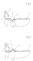
- a flange ring not belonging to the invention a one-piece and one-layer, relatively thick-walled and massive, closed, generally designated 10 Ring. He has one not shown Tube end adjacent, essentially cylindrical and at most slightly conical ring leg 12, a radial outwardly projecting mounting flange 14 and a conical to the ring leg 12 bent back part 16. Without having a hollow profile at any point or two or two. to be multi-layered still reinforcing webs or the like. is made of metal Flange ring extremely stable in itself. He's holding that forces in every direction were excellent.
- Fig. 2 it is compared to the thin-walled Sheet metal tube 18, on the end 20 of which it is placed, relatively thick-walled and solid.
- the end of the sheet metal tube 18 lies in the embodiment according to FIG. 2 on the outside of the essentially cylindrical ring leg 12 full and possibly with a press fit.
- the flange ring 10 or 10 'for many applications sufficiently close to the end 20 or 20 'of the sheet metal tube 18 or 18 'set. So much for the flange ring exposed in the axial direction, it is recommended this by riveting, screwing, spot welding or the like. secure on the sheet metal tube.
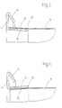
- FIG. 3 differs from the embodiment of FIGS. 1 and 2 essentially by that the inside of the pipe end 20 driven Ring leg 12 continuously with a slight taper is provided from about 2 ° to 10 °, the outer diameter of the free edge 28 of the ring leg 12 for better threading is only slightly smaller than the inside diameter of the sheet metal tube 18.
- the mounting flange 14 evenly increasing diameter of the ring leg 12 becomes the tube end 20 when hammering in the ring leg 12 expanded somewhat into the interior of the pipe and is thereby airtight and extraordinarily firm on the outside of the Ring leg 12 on without additional axial securing by riveting, spot welding or the like.
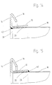
- Fig. 4 shows an embodiment in which the ring leg 12 away from the mounting flange 14 slightly conical outwards runs, and in an analogous manner, as it is easy in Fig. 3 runs conically inwards.
- the inside diameter of his free edge 28 is for easier attachment to the Pipe end 20 only slightly larger than the outside diameter of the tube 18.
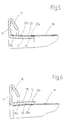
- FIG. 5 A somewhat easier to put on the pipe end 20 Variant is shown in Fig. 5.
- the ring leg has 12 an outer cylindrical portion 12a and one to the mounting flange 14 in, slightly conical Section 12b. This will only make the end section 20b of the tube end 20 slightly expanded, while the lighter cylindrical portion 12a to be threaded without widening the corresponding pipe section 20a is stuck in this.
- FIG. 5 One of the analog embodiments shown in FIG. 5 is in FIG 6, in which the ring leg 12, as in FIG. 4, is placed on the outside of the tube end 20, however also in an easier to attach cylindrical Section 12a and a slightly conical section 12b divided with only the tapered portion 12b being the end portion 20b of the tube end 20 deformed while the cylindrical Section 12a with a snug fit or press fit on the outside of the undeformed section 20a.
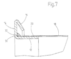
- the embodiment 7 corresponds essentially to that Embodiment according to FIG. 2.
- ring-shaped bead 34 in the circumference Ring leg 12 are provided, in which an annular Part 36 of the wall of the sheet metal tube 18 are pressed can.
- Analogous to FIG. 9 is one on the outside of the pipe end 20 slightly tapered thick ring leg 12 with egg no jumping outwards, ring-shaped around the circumference of the ring leg 20 extending bead 34 provided, in which a Wall part 36 of the sheet metal tube 18 for further fixing the Flange ring is pressed in.
- FIG. 10 corresponds essentially 8, but with the bead 34 and the in this pressed wall part 36 of the sheet metal tube 18 wider and are formed with a flat bottom and the ring leg 12 runs essentially cylindrical.
- the formation of the ring leg 12 according to the embodiment 11 is similar to the embodiment of FIG. 10.
- the sheet metal tube 18 is, however, in this embodiment no continuous bead 36, but only individual, easy to attach with pliers or the like Countersinks 36a are spaced apart. Thereby an expensive beading machine is saved.
- the embodiment according to FIG. 12 also has a cylindrical shape trained ring leg 12 extending in the circumferential direction Row of holes 38 in which corresponding parts 40 of the wall of the sheet metal tube 18 are pressed. The Pressing these hump-shaped depressions 40 can with a simple, specially designed pliers. It is clear that the hump-shaped depressions 40 at the inside seated ring leg 12 inwards and when not shown outside ring leg 12 directed outwards are.
- the ring-shaped depressions are even more practical 40 in the embodiment of FIG. 13, in which the Holes 38 are not round, as in the example in FIG. 12, but instead are elongated in the circumferential direction. You can like the holes 38 in the embodiment according to FIG. 12 in simpler Be punched out of the ring leg 12. The Sinks 40 do not have to be so in these elongated holes 38 be placed exactly what the manufacture of the anchors simplified.
- Fig. 14 shows an embodiment with an outside on the Pipe end 20 attached cylindrical or slightly conical Ring leg 12, the edge 30 of the pipe end 20 to the the mounting flange 14 adjacent end of the ring leg 12 is welded by means of a welding bead 42. Thereby this results in a further improved stability and sealing, if such is desired.
- This embodiment is also particularly suitable for thick sheet metal pipes.
- FIG. 15 An analog embodiment with an external, cylindrical or slightly conical ring leg 12 is shown in FIG. 15, in this case the free edge 28 of the ring leg 12 by means of a welding bead 42 on the outside of the sheet metal tube 18 is welded.
Landscapes
- Engineering & Computer Science (AREA)
- General Engineering & Computer Science (AREA)
- Mechanical Engineering (AREA)
- Chemical & Material Sciences (AREA)
- Combustion & Propulsion (AREA)
- Flanged Joints, Insulating Joints, And Other Joints (AREA)
- Chemically Coating (AREA)
- Medicines That Contain Protein Lipid Enzymes And Other Medicines (AREA)
- Protection Of Pipes Against Damage, Friction, And Corrosion (AREA)
Abstract
Description
Die Erfindung betrifft ein dünnwandiges Blechrohr mit auf
dieses aufgesetztem einstückigem Flanschring nach dem Oberbegriff
des Anspruchs 1.The invention relates to a thin-walled sheet metal tube
this attached one-piece flange ring according to the preamble
of
Ein Blechrohr mit Flanschring ist beispielsweise aus DE 3143893 C1 bekannt. Um zwei Blechrohrenden mit aufgesteckten Flanschringen dieser Art zur Herstellung einer Stoßverbindung miteinander zu verbinden, wird auf die kegelförmigen Spannteile ein sie eng zusammenhaltender Spannring aufgesetzt. Die Festlegung des ins Innere des Rohrendes ragenden Ringschenkels an der Wandung des Blechrohrs erfolgt bei der bekannten Vorrichtung durch einen unter Vorspannung ins Rohrinnere eingetriebenen, sich linienförmig an der Rohrinnenwand einspreizenden Ringsteg. Der Ringschenkel ist dabei im wesentlichen zweischichtig ausgebildet, wobei nur die den eingespreizten Ringsteg bildende, zur Rohrinnenwand hin liegende Schicht linienförmig an der Rohrinnenwand anliegt.A sheet metal tube with a flange ring is, for example, from DE 3143893 C1 known. Around two sheet metal tube ends with attached Flange rings of this type for producing a butt joint To connect with each other is on the conical clamping parts a clamping ring holding them tightly together. The Determination of the ring leg protruding inside the pipe end on the wall of the sheet metal tube takes place in the known Device through a pre-stressed inside the pipe driven, spreading linearly on the inner pipe wall Ring bridge. The ring leg is essentially formed in two layers, with only the spread Ring web forming, lying towards the inner tube wall Layer lies linearly on the inner pipe wall.
In ähnlicher Weise erfolgt die Festlegung des ebenfalls zweischichtig ausgebildeten Ringschenkels durch zwei parallele Einspreizkanten bei der Ausführungsform gemäß DE 3515737 C2.The definition of the is done in a similar way two-layered ring leg by two parallel Spreading edges in the embodiment according to DE 3515737 C2.
Auch der ins Rohrinnere ragende Ringschenkel nach DE 4023 470 A1 ist teils zwei-, teils dreischichtig ausgebildet und an der Rohrinnenwand angepunktet.The ring leg protruding into the pipe interior according to DE 4023 470 A1 is partly and partly three-layered and on spot on the inside wall of the pipe.
Bei einer anderen Ausführungsform gemäß EP 346143 B1 erfolgt die Befestigung des dünnwandigen und zweischichtigen Ringschenkels an der Rohrwandung durch Nieten. Das gleiche gilt für den Flanschring gemäß US 5015018.In another embodiment according to EP 346143 B1 the attachment of the thin-walled and two-layer ring leg on the pipe wall by rivets. The same goes for for the flange ring according to US 5015018.
Für mit hohen Drücken beanspruchte dickwandige Stahlrohre sind aus DE 484005 und DE 2559936 C2 Lösungen bekannt, bei denen im Vergleich zur Rohrstärke wesentlich dickere Flanschringe aufgewalzt bzw. angeschweißt werden, wobei zahlreiche Arbeitsgänge erforderlich sind, um einen festen Sitz der Flanschringe auf den Rohrenden zu erreichen.For thick-walled steel pipes subjected to high pressures solutions are known from DE 484005 and DE 2559936 C2, at which are much thicker than the pipe thickness of the flange rings are rolled or welded, with numerous Operations are required to ensure a tight fit To reach flange rings on the pipe ends.
Die dem Oberbegriff des Anspruchs 1 entsprechende US 1907397
zeigt die Befestigung eines massiven Flanschringes an einem
dünnen Blechrohr. Dabei wird zunächst das Rohrende auf den
entsprechenden Ringflansch aufgeschoben, bis es an dem nach
außen stehenden Befestigungsflansch anstößt. Dann wird das
Rohrende von außen her auf den ins Rohrinnere stehenden
Ringflansch aufgewalzt, wobei Wandmaterial des Blechrohrs in
Nuten eingedrückt wird, die auf der Außenseite des Ringflansches
vorgesehen sind. Zur zusätzlichen Sicherung des Rohrendes
wird dann ein vom Befestigungssteg schräg zum Blechrohr
hin stehender Steg unter starker Krafteinwirkung an den
Befestigungsflansch angedrückt, wodurch sein Ende am Rohrende
zur Anlage kommt. Erst nach dieser Festlegung kann ein Verbindungsring
an zwei aneinanderstoßenden Befestigungsflanschen
angebracht werden. Diese Befestigungsart erfordert
einen hohen Maschinen- und Energieaufwand.US 1907397 corresponding to the preamble of
Durch die Erfindung soll ein Flanschring dieser Art so verbessert werden, daß er einfacher und billiger herstellbar, trotzdem hoch und gleichmäßig belastbar sowie in einfacher Weise stabil und dicht am Ende eines Blechrohrs festlegbar ist. The invention is intended to improve a flange ring of this type be that it is easier and cheaper to manufacture, nevertheless high and evenly resilient as well as easier Way stable and close to the end of a sheet metal tube is.
Diese Aufgabe wird erfindungsgemäß durch die Merkmale des
Anspruchs 1 gelöst.This object is achieved by the features of
Der erfindungsgemäße Flanschring läßt sich auf einfachste Weise stabil an Blechrohr anbringen, indem er einfach auf das Ende des Blechrohrs aufgeschlagen oder in dieses eingeschlagen wird, so daß er mit Preßsitz fest und dicht an diesem Ende anliegt. Gegebenenfalls kann, falls der Preßsitz nicht ausreicht oder sich nicht einwandfrei verwirklichen läßt, zusätzlich ein anderes Haltemittel zum Festhalten des Flanschrings auf dem Blechrohr angewendet werden.The flange ring according to the invention is very simple Attach it stably to the metal pipe by simply clicking on it Opened or hammered into the end of the sheet metal tube is so that it is press-fit firmly and close to that end is present. If necessary, if the press fit is not sufficient or can not be implemented properly, in addition another holding means to hold on of the flange ring can be used on the sheet metal tube.
Vorteilhaft ist eine wenigstens teilweise wesentlich dickere Ausführung des Flanschrings gemäß Anspruch 2.One is at least partially advantageous much thicker version of the flange ring according to claim 2nd
Da das Querschnittsprofil dieser Ausführungsform des Flanschrings nicht hohl und dünnwandig, sondern einschichtig massiv und im Vergleich zur Stärke des Blechrohrs dickwandig ist, besitzt er eine sehr hohe innere Stabilität. Die kegelförmigen Spannteile bilden Auflageflächen für einen auch bei bekannten Stoßverbindungen verwendeten Spannring. Der erfindungsgemäße Flanschring muß nicht zuerst zu einem hohlen Profil geformt und sodann zu einem Ring gebogen werden, sondern läßt sich aus einem Stück pressen. Werkzeuge zum Pressen des Flanschrings lassen sich sehr einfach und billig durch Drehen herstellen. Der Materialverbrauch läßt sich dadurch minimal machen, daß die Zuschnitte der verschiedenen Flanschdurchmesser bei der Herstellung ineinandergeschachtelt werden. Die Herstellungskosten des erfindungsgemäßen Flanschrings liegen daher bei nur 50 bis 70% der Herstellungskosten eines herkömmlichen Flanschrings. Wegen der endlosen Ringform ist er gleichmäßig radial belastbar.Because the cross-sectional profile of this embodiment of the flange ring not hollow and thin-walled, but solid in one layer and is thick-walled compared to the thickness of the sheet metal tube, it has a very high internal stability. The conical Clamping parts also form contact surfaces for one Known butt joints used clamping ring. The invention Flange ring does not have to be hollow first Shaped profile and then bent into a ring, but can be pressed out of one piece. Tools for Pressing the flange ring is very easy and cheap by turning. The material consumption can be by minimizing the blanks of the different Flange diameter nested in one another during manufacture will. The manufacturing cost of the flange ring according to the invention are therefore only 50 to 70% of the manufacturing costs a conventional flange ring. Because of the endless ring shape it can be loaded evenly radially.
Durch Einschlagen des Ringschenkels ins Innere des Blechrohrendes bzw. Aufschlagen desselben auf die Außenseite des Blechrohrendes, jeweils mit sattem Sitz oder Preßsitz, ist im allgemeinen keine weitere Befestigung und Abdichtung des Ringflansches am Blechrohr erforderlich. Im Gegensatz zu den bekannten Flanschringen kann der erfindungsgemäße Flanschring jederzeit sowohl im Rohrinneren als auch an der Außenseite des Rohr befestigt werden, was je nach Verwendungszweck sehr wichtig ist. So werden für Absaugungen und Spänetransport innen glatte Rohre und infolgedessen außen aufgesetzte Flanschringe benötigt. Bei normaler Lufttechnik, insbesondere bei Wickelfalzrohren mit nach außen stehendem Wickelfalz, läßt sich der Ringschenkel jedoch innen im Rohrende befestigen. Zum leichteren Einfädeln bzw. Aufschieben des Ringschenkels in bzw. auf das Rohrende ist der freie Rand des Ringschenkels bezüglich des Rohrdurchmessers leicht eingezogen bzw. angeschrägt (innere Anbringung) bzw. leicht aufgeweitet (äußere Anbringung des Ringschenkels). Dabei liegt der Ringschenkel trotzdem im wesentlichen durchgängig an der Wandung des Blechrohrs an.By hammering the ring leg into the inside of the sheet metal tube end or hitting the same on the outside of the Tin tube end, each with a full seat or press fit, is in general no further attachment and sealing of the Ring flange on the sheet metal tube required. In contrast to the The flange ring according to the invention can be known flange rings at any time both inside the tube and on the outside be attached to the pipe, which is very dependent on the intended use important is. So for suction and chip transport inside smooth pipes and consequently on the outside Flange rings required. With normal ventilation technology, in particular in the case of folded spiral-seam tubes with the spiral fold facing outwards, the ring leg can, however, be fastened inside the pipe end. For easier threading or sliding on the ring leg in or on the pipe end is the free one Edge of the ring leg with respect to the tube diameter slightly retracted or beveled (inner attachment) or slightly expanded (outer attachment of the ring leg). Here the ring leg is still essentially continuous on the wall of the sheet metal pipe.
Bei der Ausführungsform
gemäß Anspruch 1 verläuft der Ringschenkel
leicht konisch mit einer Konizität zwischen 2° und 10° verläuft.
Dabei kann entweder
der ganze Ringschenkel gleichmäßig konisch ausgebildet
sein, oder er kann diese Konizität nur in einem axialen
Abschnitt aufweisen, gemäß Anspruch 3 vorzugsweise in dem an
den Befestigungsflansch angrenzenden Abschnitt. Durch das
Eintreiben oder Auftreiben eines solchen konischen Ringschenkels
in bzw. auf das Rohrende wird dieses entweder leicht
aufgeweitet und das Rohr legt sich eng und luftdicht um den
Ringschenkel, oder das Rohrende wird beim Aufschlagen leicht
eingezogen und liegt unter hohem Druck und luftdicht am
Ringschenkel an. Dadurch ergibt sich eine noch wesentlich
stabilere Festlegung des Flanschrings am Rohrende. Je nach
Genauigkeit und Toleranzen der zur Verwendung kommenden
Rohrdurchmesser kann der Ringschenkel kürzer oder länger
ausgebildet werden. Auch durch einen größeren Konizitätswinkel
kann größeren Rohrtoleranzen Rechnung getragen werden. In
jedem Falle läßt sich auf einfache Weise ein festes luftdichtes
Anliegen der Rohrwand am Ringschenkel erzielen. In the embodiment
according to
Bei der nur teilweise konischen Ausbildung des Ringschenkels läßt sich zunächst der zylindrische Abschnitt desselben verhältnismäßig leicht in das Rohrende einstecken oder auf dasselbe aufstecken, und sodann muß erst der Flanschring mit größerem Kraftaufwand aufgehämmert werden.When the ring leg is only partially conical the cylindrical section of the same can be started relatively easy to insert or open into the pipe end put it on, and then the flange ring has to be attached greater effort are hammered.
Die Ansprüche 4 und 5 betreffen für die Handhabung besonders zweckmäßige Ausgestaltungen des Flanschrings, wie oben erläutert.Claims 4 and 5 relate particularly to handling expedient configurations of the flange ring, as explained above.
In einzelnen Anwendungsfällen kann es erwünscht oder zweckmäßig sein, zusätzliche Abdichtung oder Festigkeit des Flanschrings am Rohrende zu erzielen. Derartige Maßnahmen betreffen die Unteransprüche 6 bis 10.In individual applications it may be desirable or appropriate be additional sealing or strength of the To achieve flange rings at the pipe end. Such measures relate to subclaims 6 to 10.
Anhand der Figuren wird die Erfindung näher erläutert. Es zeigen
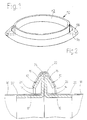
- Fig. 1
- eine Schrägansicht eines nicht zur Erfindung gehörigen Flanschrings ähnliches Bauart,
- Fig. 2
- einen axialen Teilschnitt durch eine zwei Flanschringe gemäß Fig. 1 aufweisende Stoßverbindung zwischen zwei Rohrenden,
- Fig. 3 - 10
- axiale Teilschnitte durch verschiedene Ausführungsformen eines auf ein Rohrende aufgesetzten erfindungsgemäßen Flanschrings,
- Fig. 11 - 13
- geschnittene Teilschrägansichten von weiteren Ausführungsformen eines auf ein Rohrende aufgesetzten erfindungsgemäßen Flanschrings, und
- Fig. 14 und 15
- den Fig. 3 - 10 entsprechende Teilschnitte durch weitere Ausführungsformen des erfindungsgemäßen Flanschrings.
- Fig. 1
- 2 shows an oblique view of a type of flange ring not belonging to the invention,
- Fig. 2
- 3 shows an axial partial section through a butt joint between two pipe ends according to FIG. 1,
- 3 - 10
- partial axial sections through different embodiments of a flange ring according to the invention placed on a pipe end,
- Figures 11-13
- sectional partial oblique views of further embodiments of a flange ring according to the invention placed on a pipe end, and
- 14 and 15
- 3 - 10 corresponding partial sections through further embodiments of the flange ring according to the invention.
Gleiche oder entsprechende Teile sind in den Figuren durchgehend mit den gleichen Bezugszeichen versehen.The same or corresponding parts are continuous in the figures provided with the same reference numerals.
Wie aus Fig. 1 ersichtlich, besteht eine Ausführungsform
eines nicht zur Erfindung gehörigen Flanschrings grundsätzlich aus
einem einstückigen und einschichtigen, verhältnismäßig dickwandigen
und massiven, allgemein mit 10 bezeichneten geschlossenen
Ring. Er weist einen am nicht dargestellten
Rohrende anliegenden, im wesentlichen zylindrischen und
allenfalls leicht konischen Ringschenkel 12, einen radial
nach außen ragenden Befestigungsflansch 14 und einen kegelförmig
zum Ringschenkel 12 zurückgebogenen Spannteil 16 auf.
Ohne an irgendeiner Stelle Hohlprofil aufzuweisen oder zweibzw.
mehrschichtig ausgebildet zu sein noch Verstärkungsstege
oder dergl. aufzuweisen, ist der aus Metall bestehende
Flanschring in sich außerordentlich stabil. Er hält den
auftretenden Kräften in jeder Richtung ausgezeichnet stand. As can be seen from Fig. 1, there is an embodiment
of a flange ring not belonging to the invention
a one-piece and one-layer, relatively thick-walled
and massive, closed, generally designated 10
Ring. He has one not shown
Tube end adjacent, essentially cylindrical and
at most slightly
Wie aus Fig. 2 ersichtlich, ist er im Vergleich zu dem dünnwandigen
Blechrohr 18, auf dessen Ende 20 er aufgesetzt ist,
verhältnismäßig dickwandig und massiv ausgebildet. Das Ende
des Blechrohrs 18 liegt bei der Ausführungsform gemäß Fig. 2
an der Außenseite des in wesentlichen zylindrischen Ringschenkels
12 satt und gegebenenfalls mit Preßsitz an. Dadurch
ist der Flanschring 10 bzw. 10' für viele Anwendungsfälle
ausreichend dicht am Ende 20 bzw. 20' des Blechrohrs 18 bzw.
18' festgelegt. Soweit der Flanschring einer stärkeren Belastung
in Axialrichtung ausgesetzt ist, empfiehlt es sich,
diesen durch Nieten, Verschrauben, Punktschweißen oder dgl.
am Blechrohr zu sichern. Die Teile des zweiten Flanschrings
10' sind in Fig. 2 analog mit 12', 14' und 16' bezeichnet.
Für Ausbildung und Anbringung dieses zweiten Flanschrings 10'
am zweiten Rohrende 20' gelten die oben für den Flanschring
10 gegebenen Erläuterungen ebenfalls. Zur Bildung einer
Stoßverbindung werden die beiden Befestigungsflansche 14 und
14' aneinandergelegt und mit einem Spannring 22 von im wesentlichen
V-förmigen Querschnitt mit eingelegtem Dichtungsband
24 verbunden. Der zunächst offene Spannring 22 wird
hierbei auf die beiden Spannteile 16, 16' der Flanschringe
10,10' aufgebracht und anschließend mit einer Spannschraube,
einem Spannschloß oder dgl. geschlossen. Die Spannteile 16,
16' enden jeweils in einem freien Rand 26 bzw. 26'. Dadurch
ist eine stabile und dichte Verbindung zwischen den beiden
Rohrabschnitten 18 und 18' hergestellt.As can be seen from Fig. 2, it is compared to the thin-walled
Die in Fig. 3 gezeigte erfindungsgemäße Ausführungsform unterscheidet sich von
der Ausführungsform gemäß Fig. 1 und 2 im wesentlichen dadurch,
daß der ins Innere des Rohrendes 20 eingetriebene
Ringschenkel 12 durchgehend mit einer geringfügigen Konizität
von etwa 2° bis 10° versehen ist, wobei der Außendurchmesser
des freien Randes 28 des Ringschenkels 12 zum besseren Einfädeln
nur unwesentlich kleiner ist als der Innendurchmesser
des Blechrohrs 18. Durch den bis zum Befestigungsflansch 14
hin gleichmäßig größer werdenden Durchmesser des Ringschenkels
12 wird das Rohrende 20 beim Einhämmern des Ringschenkels
12 ins Rohrinnere etwas aufgeweitet und liegt dadurch
luftdicht und außerordentlich fest auf der Außenseite des
Ringschenkels 12 auf, ohne daß eine zusätzliche Axialsicherung
durch Nieten, Punktschweißen oder dgl. erforderlich ist.The embodiment according to the invention shown in FIG. 3 differs from
the embodiment of FIGS. 1 and 2 essentially by
that the inside of the
Fig. 4 zeigt eine Ausführungsform, bei der der Ringschenkel
12 vom Befestigungsflansch 14 weg leicht konisch nach außen
verläuft, und zwar in analoger Weise, wie er in Fig. 3 leicht
konisch nach innen verläuft. Der Innendurchmesser seines
freien Randes 28 ist dabei zum leichteren Aufstecken auf das
Rohrende 20 nur geringfügig größer als der Außendurchmesser
des Rohrs 18. Durch das Aufschlagen des Ringschenkels 12
unter Kraftanwendung auf die Außenseite des Rohrendes 20 wird
dieses leicht zusammengedrückt, wodurch es außerordentlich
fest im Ringschenkel 12 sitzt.Fig. 4 shows an embodiment in which the
Eine etwas einfacher auf das Rohrende 20 aufzusteckende
Variante ist in Fig. 5 dargestellt. Hierbei weist der Ringschenkel
12 einen äußeren zylindrischen Abschnitt 12a und
einen zum Befestigungsflansch 14 in gelegenen, leicht konischen
Abschnitt 12b auf. Dadurch wird nur der Endabschnitt
20b des Rohrendes 20 leicht aufgeweitet, während der leichter
einzufädelnde zylindrische Abschnitt 12a ohne Aufweitung des
entsprechenden Rohrabschnitts 20a in diesem festsitzt.A somewhat easier to put on the
Eine der in Fig. 5 gezeigten analoge Ausführungsform ist in
Fig. 6 gezeigt, bei der der Ringschenkel 12, wie in Fig. 4,
auf die Außenseite des Rohrendes 20 aufgesetzt ist, jedoch
ebenfalls in einen leichter aufzusteckenden zylindrischen
Abschnitt 12a und einen leicht konischen Abschnitt 12b unterteilt
ist, wobei nur der konische Abschnitt 12b den Endabschnitt
20b des Rohrendes 20 verformt, während der zylindrische
Abschnitt 12a mit Paßsitz oder Preßsitz auf der Außenseite
des unverformten Abschnits 20a aufliegt. Die Ausführungsform
gemäß der Fig. 7 entspricht im wesentlichen der
Ausführungsform gemäß Fig. 2. Zusätzlich ist hier am Rand 30
des Blechrohrendes 20 im Winkel zwischen dem im wesentlichen
zylindrischen oder leicht konischen Ringschenkel 12 und dem
Befestigungsflansch 14 eine Dichtungsrauße 32, z.B. aus
Mastik, angebracht, die in Fällen, in denen eine noch bessere
Gas- bzw. Flüssigkeitsabdichtung erwünscht ist, zweckmäßig
sein kann.One of the analog embodiments shown in FIG. 5 is in FIG
6, in which the
Falls in extremen Fällen die Befestigung des Ringschenkels 12
am Rohrende 20 mit Preßsitz nicht ausreichen sollte, kann zur
Sicherheit bei einem am Rohrinneren anliegenden leicht konischen
dicken Ringschenkel 12 gemäß Fig. 8 eine nach innen
springende, ringförmig um den Umfang verlaufende Sicke 34 im
Ringschenkel 12 vorgesehen werden, in welche ein ringförmiger
Teil 36 der Wandung des Blechrohrs 18 eingedrückt werden
kann.If, in extreme cases, the fastening of the
Analog ist gemäß Fig. 9 ein an der Außenseite des Rohrendes
20 leicht konisch aniegender dicker Ringschenkel 12 mit eienr
nach außen springenden, ringförmig um den Umfang des Ringschenkels
20 verlaufenden Sicke 34 versehen, in welche ein
Wandungsteil 36 des Blechrohrs 18 zur weiteren Festlegung des
Flanschrings eingedrückt wird. Analogous to FIG. 9 is one on the outside of the
Die Ausführungsform der Fig. 10 entspricht im wesentlichen
derjenigen von Fig. 8, wobei jedoch die Sicke 34 und der in
diese gedrückte Wandungsteil 36 des Blechrohrs 18 breiter und
mit einem flachen Boden ausgebildet sind und der Ringschenkel
12 im wesentlichen zylindrisch verläuft.The embodiment of FIG. 10 corresponds essentially
8, but with the
Die Ausbildung des Ringschenkels 12 der Ausführungsform gemäß
Fig. 11 ist ähnlich wie bei der Ausführungsform gemäß Fig.
10. Zur Vereinfachung des Eindrückens eines Teils der Wandung
des Blechrohrs 18 wird jedoch bei dieser Ausführungsform
keine durchgehende Sicke 36, sondern es werden nur einzelne,
in einfacher Weise mit einer Zange oder dergl. anzubringende
Einsenkungen 36a in Abständen voneinander angebracht. Dadurch
wird eine kostspielige Sickenmaschine eingespart. Bei der
Ausführungsform gemäß Fig. 12 weist der ebenfalls zylindrisch
ausgebildete Ringschenkel 12 eine in Umfangsrichtung verlaufende
Reihe von Löchern 38 auf, in welche entsprechende Teile
40 der Wandung des Blechrohrs 18 eingedrückt werden. Das
Eindrücken dieser buckelförmigen Einsenkungen 40 kann mit
einer einfachen, speziell gestalteten Zange erfolgen. Es ist
klar, daß die buckelförmigen Einsenkungen 40 beim innen
sitzenden Ringschenkel 12 nach innen und beim nicht dargestellten
außen sitzenden Ringschenkel 12 nach außen gerichtet
sind.The formation of the
Noch praktischer ist das Eindrücken der ringförmigen Einsenkungen
40 bei der Ausführungsform gemäß Fig. 13, bei der die
Löcher 38 nicht rund wie beim Beispiel der Fig. 12, sondern
in Umfangsrichtung länglich ausgebildet sind. Sie können wie
die Löcher 38 bei der Ausführungsform gemäß Fig. 12 in einfacher
Weise aus dem Ringschenkel 12 ausgestanzt werden. Die
Einsenkungen 40 müssen bei diesen Langlöchern 38 nicht so
genau placiert werden, was die Herstellung der Verankerungen
vereinfacht.The ring-shaped depressions are even more practical
40 in the embodiment of FIG. 13, in which the
Fig. 14 zeigt eine Ausführungsform mit einem außen auf das
Rohrende 20 aufgesetzten zylindrischen oder leicht konischen
Ringschenkel 12, wobei der Rand 30 des Rohrendes 20 an das an
den Befestigungsflansch 14 angrenzende Ende des Ringschenkels
12 mittels einer Schweißraupe 42 angeschweißt ist. Dadurch
ergibt sich eine nochmals verbesserte Stabilität und Abdichtung,
wenn eine solche erwünscht ist. Diese Ausführungsform
eignet sich auch für dickere Blechrohre besonders gut.Fig. 14 shows an embodiment with an outside on the
Eine analoge Ausführungsform mit außen aufgesetztem, zylindrischem
oder leicht konischem Ringschenkel 12 zeigt Fig. 15,
wobei in diesem Fall der freie Rand 28 des Ringschenkels 12
mittels einer Schweißraupe 42 an der Außenseite des Blechrohrs
18 angeschweißt ist.An analog embodiment with an external, cylindrical
or slightly
Claims (10)
- Thin-walled sheet-metal pipe (18) having an integral flanged ring (10) mounted thereon for making a butt joint between two pipe sections (18, 18') having an approximately radially outwardly projecting attachment flange (14) which carries, at its readially outer end, a freely ending clamping part (16) bent round conically towards the sheet-metal pipe (18), and having an annular limb (12) projecting from the radially internal end of the attachment flange (14), the flanged ring (10) having a single-layer solid profile and the external diameter of the annular limb (12) being matched to the internal diameter of the sheet-metal pipe (18, 20) or the internal diameter of the annular limb (12) being matched to the external diameter of the sheet-metal pipe (18, 20), the annular limb (12) extending at least partly in a slightly conical fashion and the external diameter of the free rim (28) of the annular limb being slightly smaller than the internal diameter of the sheet-metal pipe (18) or the internal diameter of the free rim (28) being slightly larger than the external diameter of the sheet-metal pipe (18), respectively, characterized in that the conicity of the annular limb (12) is between 2° and 10° and, when forced on, brings about a widening or compression, respectively, of the end (20) of the sheet-metal pipe (18) and in that the end (20) of the sheet-metal pipe (18) is held only by close-fitting and airtight all-round contact with the outside or inside, respectively, of the annular limb (12) by press-fitting to the latter.
- Sheet-metal pipe having a flanged ring according to Claim 1, characterized in that the solid profile of the flanged ring (10) is thick-walled compared with the sheet-metal thickness of the sheet-metal pipe (18).
- Sheet-metal pipe having a flanged ring according to Claim 1 or 2, characterized in that the annular ring (12) extends slightly conically at least in a section (12b) adjacent to the attachment flange (14).
- Sheet-metal pipe having a flanged ring according to one of the preceding claims, characterized in that the diameter of the annular limb (12) decreases from the attachment flange (14) towards its free rim (28) and the external diameter of the free rim (28) is slightly less than the internal diameter of the sheet-metal pipe (18).
- Sheet-metal pipe having a flanged ring according to one of Claims 1 to 3, characterized in that the diameter of the annular limb (12) increases from the attachment flange (14) towards its free end and the internal diameter of the free rim (28) is slightly larger than the external diameter of the sheet-metal pipe (18).
- Sheet-metal pipe having a flanged ring according to one of the preceding claims, characterized in that it is sealed by means of a sealing bead (32) with respect to the end (20) of the sheet-metal pipe (18).
- Sheet-metal pipe having a flanged ring according to one of the preceding claims, characterized in that the annular limb (12) has a series, extending in the circumferential direction, of holes (38) into which the wall (40) of the sheet-metal pipe (18, 20) can be pressed.
- Sheet-metal pipe having a flanged ring according to Claim 7, characterized in that the holes (38) have an elongated shape in the circumferential direction.
- Sheet-metal pipe having a flanged ring according to one of the preceding claims, characterized in that the sheet-metal pipe (18, 20) is welded to the annular limb (12).
- Sheet-metal pipe having a flanged ring according to one of the preceding claims, characterized in that interlocking annular corrugations (34, 36) are pressed into the annular limb (12) and wall of the sheet-metal pipe (18, 20).
Applications Claiming Priority (2)
| Application Number | Priority Date | Filing Date | Title |
|---|---|---|---|
| DE4308013 | 1993-03-13 | ||
| DE4308013A DE4308013A1 (en) | 1993-03-13 | 1993-03-13 | Flange ring that can be placed on a thin-walled sheet metal tube |
Publications (2)
| Publication Number | Publication Date |
|---|---|
| EP0616162A1 EP0616162A1 (en) | 1994-09-21 |
| EP0616162B1 true EP0616162B1 (en) | 1998-05-20 |
Family
ID=6482711
Family Applications (1)
| Application Number | Title | Priority Date | Filing Date |
|---|---|---|---|
| EP94102685A Expired - Lifetime EP0616162B1 (en) | 1993-03-13 | 1994-02-23 | Thin-walled pipe with one-piece flange ring attached thereto |
Country Status (8)
| Country | Link |
|---|---|
| EP (1) | EP0616162B1 (en) |
| JP (1) | JPH0755075A (en) |
| AT (1) | ATE166440T1 (en) |
| CA (1) | CA2117216A1 (en) |
| DE (2) | DE4308013A1 (en) |
| DK (1) | DK0616162T3 (en) |
| ES (1) | ES2117162T3 (en) |
| TW (1) | TW255002B (en) |
Families Citing this family (19)
| Publication number | Priority date | Publication date | Assignee | Title |
|---|---|---|---|---|
| DE19547982A1 (en) * | 1995-12-21 | 1997-06-26 | Meinig Metu System | Butt joint of air duct sections |
| DE19728655A1 (en) * | 1997-07-04 | 1999-02-04 | Meinig Metu System | Air-duct pipe end butt joint for two pipe ends |
| US6540266B2 (en) * | 2000-06-19 | 2003-04-01 | Macdonald-Miller Inc. | Spin forming a tubular workpiece to form a radial flange on a tubular flange and a thick rim on the radial flange |
| US6758502B2 (en) | 2001-01-17 | 2004-07-06 | Lindab Ab | Coupling ring for ventilation ducts, and method of connecting ventilation ducts |
| DE20105012U1 (en) | 2001-03-22 | 2001-09-13 | Kutzner + Weber GmbH & Co. KG, 82216 Maisach | Sealing arrangement for sealing a connection point of two interconnected pipes |
| DE10215112C1 (en) | 2002-04-05 | 2003-09-25 | Meinig Metu System | Abutting pipe connection uses clamping device for securing annular edges of coupling flanges at ends of abutting pipe sections together |
| US7004512B2 (en) * | 2002-06-19 | 2006-02-28 | Voss Industries, Inc. | Indented apex V-retainer coupling with cushion |
| KR100517067B1 (en) * | 2002-06-25 | 2005-09-27 | 주식회사 한미파슨스건축사사무소 | joint assembles of flue, multi layer flue and the installation method using the same |
| DE60315315T2 (en) * | 2002-08-28 | 2008-04-17 | Dinex A/S | BELT, PIPE CONNECTION AND EXHAUST SYSTEM |
| JP4568586B2 (en) * | 2004-11-18 | 2010-10-27 | パナソニック環境エンジニアリング株式会社 | Method for forming air conditioning duct |
| US8021469B2 (en) | 2005-07-14 | 2011-09-20 | Access Business Group International Llc | Control methods for an air treatment system |
| JP2009299750A (en) * | 2008-06-12 | 2009-12-24 | Suiken:Kk | Polyethylene pipe joint structure |
| US10539337B2 (en) | 2009-11-24 | 2020-01-21 | Jeffrey Allen Hermanson | Sealed and/or reinforced flanged ring connector for single- and double-wall HVAC ducting |
| CA2781617C (en) | 2009-11-24 | 2018-06-19 | Jeffrey Allen Hermanson | Standing seam connectors for ducting |
| FR2963404B1 (en) * | 2010-07-27 | 2014-02-07 | Caillau Ets | CLAMPING SYSTEM FOR CONNECTING AND PRE-ASSEMBLING A FIRST AND A SECOND TUBE |
| DE202016104450U1 (en) * | 2016-08-12 | 2017-11-14 | Promat Gmbh | Piping |
| JP7048046B2 (en) * | 2018-01-12 | 2022-04-05 | 株式会社新富士空調 | Deformable duct |
| IT202100005453A1 (en) * | 2021-03-09 | 2022-09-09 | Geeico Eng S R L | SYSTEM FOR THE SUCTION OF TRIM AND SCRAP FROM MECHANICAL WORKINGS |
| CN118274194A (en) * | 2024-05-11 | 2024-07-02 | 江苏中康金属材料有限公司 | Stainless steel water pipe easy to expand |
Family Cites Families (10)
| Publication number | Priority date | Publication date | Assignee | Title |
|---|---|---|---|---|
| DE484005C (en) * | 1924-08-24 | 1929-10-09 | Borsig G M B H Maschinenfabrik | Flanged pipe with rolled flange |
| US1907397A (en) * | 1930-08-18 | 1933-05-02 | Kosik Adalbert | Pipe joint |
| US2005267A (en) * | 1932-09-29 | 1935-06-18 | Rehder Christian | Pipe flange connection |
| US3437358A (en) * | 1966-09-01 | 1969-04-08 | Anchor Coupling Co Inc | Tube end connection |
| DE2559936C2 (en) * | 1975-11-04 | 1983-03-17 | Wilhelm 4150 Krefeld Schulz | Slip-on welding flange |
| DE3143893C1 (en) * | 1981-11-05 | 1983-04-21 | Karl Meinig KG, 7201 Rietheim-Weilheim | Flange ring for pipes |
| DE3314064A1 (en) * | 1983-04-19 | 1984-10-25 | Karl Meinig KG, 7201 Rietheim-Weilheim | Butt connection between two sheet-metal tubular sections |
| DE3314129A1 (en) * | 1983-04-19 | 1984-10-25 | Karl Meinig KG, 7201 Rietheim-Weilheim | Clamping ring for butt connections between two thin-walled round sheet-metal tubular sections, and a clamping apparatus for the same |
| US5016925A (en) * | 1987-04-27 | 1991-05-21 | Davis Paul K | Pipe coupling and method of forming |
| US5015018A (en) * | 1988-06-10 | 1991-05-14 | Ductmate Industries, Inc. | Duct connector |
-
1993
- 1993-03-13 DE DE4308013A patent/DE4308013A1/en not_active Withdrawn
- 1993-03-24 TW TW082102206A patent/TW255002B/zh active
-
1994
- 1994-02-23 DK DK94102685T patent/DK0616162T3/en active
- 1994-02-23 DE DE59405971T patent/DE59405971D1/en not_active Expired - Fee Related
- 1994-02-23 ES ES94102685T patent/ES2117162T3/en not_active Expired - Lifetime
- 1994-02-23 AT AT94102685T patent/ATE166440T1/en not_active IP Right Cessation
- 1994-02-23 EP EP94102685A patent/EP0616162B1/en not_active Expired - Lifetime
- 1994-03-08 CA CA002117216A patent/CA2117216A1/en not_active Abandoned
- 1994-03-10 JP JP6039547A patent/JPH0755075A/en active Pending
Also Published As
| Publication number | Publication date |
|---|---|
| TW255002B (en) | 1995-08-21 |
| DK0616162T3 (en) | 1999-03-08 |
| CA2117216A1 (en) | 1994-09-14 |
| JPH0755075A (en) | 1995-03-03 |
| ES2117162T3 (en) | 1998-08-01 |
| ATE166440T1 (en) | 1998-06-15 |
| EP0616162A1 (en) | 1994-09-21 |
| DE4308013A1 (en) | 1994-09-15 |
| DE59405971D1 (en) | 1998-06-25 |
Similar Documents
| Publication | Publication Date | Title |
|---|---|---|
| EP0616162B1 (en) | Thin-walled pipe with one-piece flange ring attached thereto | |
| DE4041679C2 (en) | Tube Fitting | |
| DE3143893C1 (en) | Flange ring for pipes | |
| CH649613A5 (en) | TUBE CLAMP. | |
| DE2535264A1 (en) | THREADING OR MOTHER | |
| DE3105170A1 (en) | VIBRATION DAMPER OR SHOCK ABSORBER WITH AT LEAST ONE FITTING ARRANGED ON THE CONTAINER TUBE | |
| DE2521930C2 (en) | Pipe connector | |
| EP0925467B1 (en) | Flexible hose sleeve | |
| DE10023149A1 (en) | High pressure fuel injection pipe for diesel engine, has pair of independent units of outer pipe joined together in both ends through seal ring | |
| DE10107246C5 (en) | Pipe arrangement and pipe element | |
| DE29606683U1 (en) | Connection between a component and a tubular line element | |
| DE19633435C1 (en) | Worm thread clamp | |
| DE2454755A1 (en) | FLANGE CONNECTION AND METHOD OF MANUFACTURING IT | |
| DE2221674A1 (en) | Hose coupling | |
| DE10152975C1 (en) | Press fitting for the connection of at least one pipe | |
| WO1982003440A1 (en) | Sealed coupling of plastic material pipes resisting to thrust forces | |
| DE69313956T2 (en) | Radial tension hose for connection to a pipe end; Hose connection with this hose | |
| DE20120098U1 (en) | Component connection for chassis components | |
| EP0595041A2 (en) | Connection, in particular to a hole accessible only from one side | |
| DE3501583A1 (en) | Device for the axial connection of two sleeveless pipes | |
| DE8002221U1 (en) | ROLLER FASTENING SLEEVE | |
| DE3537504C1 (en) | Butt joint between two thin-walled, round sheet-metal tube portions | |
| DE3924037C1 (en) | ||
| DE3004837C2 (en) | Heat exchanger | |
| CH636933A5 (en) | Device for attaching an element to a pipe |
Legal Events
| Date | Code | Title | Description |
|---|---|---|---|
| PUAI | Public reference made under article 153(3) epc to a published international application that has entered the european phase |
Free format text: ORIGINAL CODE: 0009012 |
|
| AK | Designated contracting states |
Kind code of ref document: A1 Designated state(s): AT CH DE DK ES FR GB IT LI |
|
| 17P | Request for examination filed |
Effective date: 19941001 |
|
| 17Q | First examination report despatched |
Effective date: 19960416 |
|
| GRAG | Despatch of communication of intention to grant |
Free format text: ORIGINAL CODE: EPIDOS AGRA |
|
| GRAG | Despatch of communication of intention to grant |
Free format text: ORIGINAL CODE: EPIDOS AGRA |
|
| GRAH | Despatch of communication of intention to grant a patent |
Free format text: ORIGINAL CODE: EPIDOS IGRA |
|
| GRAH | Despatch of communication of intention to grant a patent |
Free format text: ORIGINAL CODE: EPIDOS IGRA |
|
| GRAA | (expected) grant |
Free format text: ORIGINAL CODE: 0009210 |
|
| AK | Designated contracting states |
Kind code of ref document: B1 Designated state(s): AT CH DE DK ES FR GB IT LI |
|
| REF | Corresponds to: |
Ref document number: 166440 Country of ref document: AT Date of ref document: 19980615 Kind code of ref document: T |
|
| REG | Reference to a national code |
Ref country code: CH Ref legal event code: NV Representative=s name: DIPL.-ING. ETH H. R. WERFFELI PATENTANWALT Ref country code: CH Ref legal event code: EP |
|
| GBT | Gb: translation of ep patent filed (gb section 77(6)(a)/1977) |
Effective date: 19980520 |
|
| ET | Fr: translation filed | ||
| REF | Corresponds to: |
Ref document number: 59405971 Country of ref document: DE Date of ref document: 19980625 |
|
| ITF | It: translation for a ep patent filed | ||
| REG | Reference to a national code |
Ref country code: ES Ref legal event code: FG2A Ref document number: 2117162 Country of ref document: ES Kind code of ref document: T3 |
|
| REG | Reference to a national code |
Ref country code: DK Ref legal event code: T3 |
|
| PLBE | No opposition filed within time limit |
Free format text: ORIGINAL CODE: 0009261 |
|
| STAA | Information on the status of an ep patent application or granted ep patent |
Free format text: STATUS: NO OPPOSITION FILED WITHIN TIME LIMIT |
|
| 26N | No opposition filed | ||
| REG | Reference to a national code |
Ref country code: GB Ref legal event code: IF02 |
|
| PGFP | Annual fee paid to national office [announced via postgrant information from national office to epo] |
Ref country code: GB Payment date: 20050105 Year of fee payment: 12 |
|
| PGFP | Annual fee paid to national office [announced via postgrant information from national office to epo] |
Ref country code: FR Payment date: 20050216 Year of fee payment: 12 |
|
| PGFP | Annual fee paid to national office [announced via postgrant information from national office to epo] |
Ref country code: AT Payment date: 20050218 Year of fee payment: 12 |
|
| PGFP | Annual fee paid to national office [announced via postgrant information from national office to epo] |
Ref country code: CH Payment date: 20050221 Year of fee payment: 12 Ref country code: DK Payment date: 20050221 Year of fee payment: 12 |
|
| PG25 | Lapsed in a contracting state [announced via postgrant information from national office to epo] |
Ref country code: GB Free format text: LAPSE BECAUSE OF NON-PAYMENT OF DUE FEES Effective date: 20060223 Ref country code: AT Free format text: LAPSE BECAUSE OF NON-PAYMENT OF DUE FEES Effective date: 20060223 |
|
| PG25 | Lapsed in a contracting state [announced via postgrant information from national office to epo] |
Ref country code: LI Free format text: LAPSE BECAUSE OF NON-PAYMENT OF DUE FEES Effective date: 20060228 Ref country code: DK Free format text: LAPSE BECAUSE OF NON-PAYMENT OF DUE FEES Effective date: 20060228 Ref country code: CH Free format text: LAPSE BECAUSE OF NON-PAYMENT OF DUE FEES Effective date: 20060228 |
|
| PGFP | Annual fee paid to national office [announced via postgrant information from national office to epo] |
Ref country code: IT Payment date: 20060228 Year of fee payment: 13 |
|
| REG | Reference to a national code |
Ref country code: DK Ref legal event code: EBP |
|
| REG | Reference to a national code |
Ref country code: CH Ref legal event code: PL |
|
| GBPC | Gb: european patent ceased through non-payment of renewal fee |
Effective date: 20060223 |
|
| REG | Reference to a national code |
Ref country code: FR Ref legal event code: ST Effective date: 20061031 |
|
| PG25 | Lapsed in a contracting state [announced via postgrant information from national office to epo] |
Ref country code: FR Free format text: LAPSE BECAUSE OF NON-PAYMENT OF DUE FEES Effective date: 20060228 |
|
| PGFP | Annual fee paid to national office [announced via postgrant information from national office to epo] |
Ref country code: DE Payment date: 20080328 Year of fee payment: 15 |
|
| PG25 | Lapsed in a contracting state [announced via postgrant information from national office to epo] |
Ref country code: IT Free format text: LAPSE BECAUSE OF NON-PAYMENT OF DUE FEES Effective date: 20070223 |
|
| PG25 | Lapsed in a contracting state [announced via postgrant information from national office to epo] |
Ref country code: DE Free format text: LAPSE BECAUSE OF NON-PAYMENT OF DUE FEES Effective date: 20090901 |
|
| PGFP | Annual fee paid to national office [announced via postgrant information from national office to epo] |
Ref country code: ES Payment date: 20120326 Year of fee payment: 19 |
|
| REG | Reference to a national code |
Ref country code: ES Ref legal event code: FD2A Effective date: 20140409 |
|
| PG25 | Lapsed in a contracting state [announced via postgrant information from national office to epo] |
Ref country code: ES Free format text: LAPSE BECAUSE OF NON-PAYMENT OF DUE FEES Effective date: 20130224 |