EP0614781B1 - Vehicle seat and its application to a rear seat - Google Patents
Vehicle seat and its application to a rear seat Download PDFInfo
- Publication number
- EP0614781B1 EP0614781B1 EP19940400474 EP94400474A EP0614781B1 EP 0614781 B1 EP0614781 B1 EP 0614781B1 EP 19940400474 EP19940400474 EP 19940400474 EP 94400474 A EP94400474 A EP 94400474A EP 0614781 B1 EP0614781 B1 EP 0614781B1
- Authority
- EP
- European Patent Office
- Prior art keywords
- seat
- slide
- floor
- seat according
- integral
- Prior art date
- Legal status (The legal status is an assumption and is not a legal conclusion. Google has not performed a legal analysis and makes no representation as to the accuracy of the status listed.)
- Expired - Lifetime
Links
Images


Classifications
-
- B—PERFORMING OPERATIONS; TRANSPORTING
- B60—VEHICLES IN GENERAL
- B60N—SEATS SPECIALLY ADAPTED FOR VEHICLES; VEHICLE PASSENGER ACCOMMODATION NOT OTHERWISE PROVIDED FOR
- B60N2/00—Seats specially adapted for vehicles; Arrangement or mounting of seats in vehicles
- B60N2/02—Seats specially adapted for vehicles; Arrangement or mounting of seats in vehicles the seat or part thereof being movable, e.g. adjustable
- B60N2/04—Seats specially adapted for vehicles; Arrangement or mounting of seats in vehicles the seat or part thereof being movable, e.g. adjustable the whole seat being movable
- B60N2/06—Seats specially adapted for vehicles; Arrangement or mounting of seats in vehicles the seat or part thereof being movable, e.g. adjustable the whole seat being movable slidable
- B60N2/08—Seats specially adapted for vehicles; Arrangement or mounting of seats in vehicles the seat or part thereof being movable, e.g. adjustable the whole seat being movable slidable characterised by the locking device
- B60N2/0831—Movement of the latch
- B60N2/0837—Movement of the latch pivoting
- B60N2/0856—Movement of the latch pivoting about a vertical axis
-
- B—PERFORMING OPERATIONS; TRANSPORTING
- B60—VEHICLES IN GENERAL
- B60N—SEATS SPECIALLY ADAPTED FOR VEHICLES; VEHICLE PASSENGER ACCOMMODATION NOT OTHERWISE PROVIDED FOR
- B60N2/00—Seats specially adapted for vehicles; Arrangement or mounting of seats in vehicles
- B60N2/02—Seats specially adapted for vehicles; Arrangement or mounting of seats in vehicles the seat or part thereof being movable, e.g. adjustable
- B60N2/04—Seats specially adapted for vehicles; Arrangement or mounting of seats in vehicles the seat or part thereof being movable, e.g. adjustable the whole seat being movable
- B60N2/06—Seats specially adapted for vehicles; Arrangement or mounting of seats in vehicles the seat or part thereof being movable, e.g. adjustable the whole seat being movable slidable
- B60N2/07—Slide construction
- B60N2/0702—Slide construction characterised by its cross-section
- B60N2/0705—Slide construction characterised by its cross-section omega-shaped
-
- B—PERFORMING OPERATIONS; TRANSPORTING
- B60—VEHICLES IN GENERAL
- B60N—SEATS SPECIALLY ADAPTED FOR VEHICLES; VEHICLE PASSENGER ACCOMMODATION NOT OTHERWISE PROVIDED FOR
- B60N2/00—Seats specially adapted for vehicles; Arrangement or mounting of seats in vehicles
- B60N2/02—Seats specially adapted for vehicles; Arrangement or mounting of seats in vehicles the seat or part thereof being movable, e.g. adjustable
- B60N2/04—Seats specially adapted for vehicles; Arrangement or mounting of seats in vehicles the seat or part thereof being movable, e.g. adjustable the whole seat being movable
- B60N2/06—Seats specially adapted for vehicles; Arrangement or mounting of seats in vehicles the seat or part thereof being movable, e.g. adjustable the whole seat being movable slidable
- B60N2/07—Slide construction
- B60N2/0702—Slide construction characterised by its cross-section
- B60N2/0715—C or U-shaped
-
- B—PERFORMING OPERATIONS; TRANSPORTING
- B60—VEHICLES IN GENERAL
- B60N—SEATS SPECIALLY ADAPTED FOR VEHICLES; VEHICLE PASSENGER ACCOMMODATION NOT OTHERWISE PROVIDED FOR
- B60N2/00—Seats specially adapted for vehicles; Arrangement or mounting of seats in vehicles
- B60N2/02—Seats specially adapted for vehicles; Arrangement or mounting of seats in vehicles the seat or part thereof being movable, e.g. adjustable
- B60N2/04—Seats specially adapted for vehicles; Arrangement or mounting of seats in vehicles the seat or part thereof being movable, e.g. adjustable the whole seat being movable
- B60N2/06—Seats specially adapted for vehicles; Arrangement or mounting of seats in vehicles the seat or part thereof being movable, e.g. adjustable the whole seat being movable slidable
- B60N2/07—Slide construction
- B60N2/0722—Constructive details
- B60N2/073—Reinforcement members preventing slide dislocation
-
- B—PERFORMING OPERATIONS; TRANSPORTING
- B60—VEHICLES IN GENERAL
- B60N—SEATS SPECIALLY ADAPTED FOR VEHICLES; VEHICLE PASSENGER ACCOMMODATION NOT OTHERWISE PROVIDED FOR
- B60N2/00—Seats specially adapted for vehicles; Arrangement or mounting of seats in vehicles
- B60N2/02—Seats specially adapted for vehicles; Arrangement or mounting of seats in vehicles the seat or part thereof being movable, e.g. adjustable
- B60N2/04—Seats specially adapted for vehicles; Arrangement or mounting of seats in vehicles the seat or part thereof being movable, e.g. adjustable the whole seat being movable
- B60N2/06—Seats specially adapted for vehicles; Arrangement or mounting of seats in vehicles the seat or part thereof being movable, e.g. adjustable the whole seat being movable slidable
- B60N2/08—Seats specially adapted for vehicles; Arrangement or mounting of seats in vehicles the seat or part thereof being movable, e.g. adjustable the whole seat being movable slidable characterised by the locking device
- B60N2/0812—Location of the latch
- B60N2/0825—Location of the latch outside the rail
-
- B—PERFORMING OPERATIONS; TRANSPORTING
- B60—VEHICLES IN GENERAL
- B60N—SEATS SPECIALLY ADAPTED FOR VEHICLES; VEHICLE PASSENGER ACCOMMODATION NOT OTHERWISE PROVIDED FOR
- B60N2/00—Seats specially adapted for vehicles; Arrangement or mounting of seats in vehicles
- B60N2/24—Seats specially adapted for vehicles; Arrangement or mounting of seats in vehicles for particular purposes or particular vehicles
- B60N2/30—Non-dismountable or dismountable seats storable in a non-use position, e.g. foldable spare seats
- B60N2/3002—Non-dismountable or dismountable seats storable in a non-use position, e.g. foldable spare seats back-rest movements
- B60N2/3004—Non-dismountable or dismountable seats storable in a non-use position, e.g. foldable spare seats back-rest movements by rotation only
- B60N2/3009—Non-dismountable or dismountable seats storable in a non-use position, e.g. foldable spare seats back-rest movements by rotation only about transversal axis
- B60N2/3011—Non-dismountable or dismountable seats storable in a non-use position, e.g. foldable spare seats back-rest movements by rotation only about transversal axis the back-rest being hinged on the cushion, e.g. "portefeuille movement"
-
- B—PERFORMING OPERATIONS; TRANSPORTING
- B60—VEHICLES IN GENERAL
- B60N—SEATS SPECIALLY ADAPTED FOR VEHICLES; VEHICLE PASSENGER ACCOMMODATION NOT OTHERWISE PROVIDED FOR
- B60N2/00—Seats specially adapted for vehicles; Arrangement or mounting of seats in vehicles
- B60N2/24—Seats specially adapted for vehicles; Arrangement or mounting of seats in vehicles for particular purposes or particular vehicles
- B60N2/32—Seats specially adapted for vehicles; Arrangement or mounting of seats in vehicles for particular purposes or particular vehicles convertible for other use
- B60N2/36—Seats specially adapted for vehicles; Arrangement or mounting of seats in vehicles for particular purposes or particular vehicles convertible for other use into a loading platform
- B60N2/366—Seats specially adapted for vehicles; Arrangement or mounting of seats in vehicles for particular purposes or particular vehicles convertible for other use into a loading platform characterised by the locking device
-
- B—PERFORMING OPERATIONS; TRANSPORTING
- B60—VEHICLES IN GENERAL
- B60N—SEATS SPECIALLY ADAPTED FOR VEHICLES; VEHICLE PASSENGER ACCOMMODATION NOT OTHERWISE PROVIDED FOR
- B60N2205/00—General mechanical or structural details
- B60N2205/30—Seat or seat parts characterised by comprising plural parts or pieces
- B60N2205/35—Seat, bench or back-rests being split laterally in two or more parts
Definitions
- the present invention relates to seats for land motor vehicles and, more particularly, adjustable and tiltable seats intended to be mounted on the vehicle floor.
- the seats for land motor vehicles consist in particular of a seat to which is associated a backrest.
- the construction of such a seat is such that, most often, the backrest is tiltable relative to the seat or even foldable against the latter, in a direction orthogonal to the longitudinal axis of the vehicle.
- the seat as a whole is most often adjustable in translation in a direction parallel to the longitudinal axis of the vehicle and further, if necessary, this seat in its example, usually after folding the backrest against its seat, is also tiltable in a direction which is orthogonal to the longitudinal axis of the vehicle.
- Such a configuration is sometimes adopted for the front seats, in particular for so-called coupe vehicles in order to facilitate access to the seats in the rear seats, or also for the rear seats in order to free up additional volume enabling bulky objects to be loaded.
- This is the case for example of so-called three-door or five-door vehicles which make it possible to transform a so-called "touring or sedan" vehicle into a "station wagon".
- WO 83/03081 describes a seat of the adjustable and tiltable type, intended to be mounted on the floor of a land motor vehicle.
- EP-A-0 558 380 which is included in the state of the art within the meaning of Article 54 (3) EPC, describes a seat of the aforementioned type comprising an articulated composite lock which makes it possible to satisfy most of the contradictory constraints imposed specified above.
- the solution described by this document also allows automatic adaptation to the interval of deviations due to manufacturing tolerances, in particular of the floor of a vehicle.
- a difficulty still remains when, after having been completely tilted to save space, a rear seat is redeployed in the "road” position capable of being occupied by an occupant and rests in principle against the floor of the vehicle.
- a user grasps the seat to tilt it into the use or "road” position from the rear of the vehicle not only does it describe an arc of a circle at the seat against which the backrest is folded, but it also tends to modify the longitudinal position in translation of the entire seat relative to the floor.
- the object of the invention is to remedy this type of disadvantage detrimental to safety using an improved seat, adjustable and tiltable, intended to be mounted on the floor of a land motor vehicle.
- the subject of the invention is a seat of the adjustable and tiltable type, intended to be mounted on the floor of a land motor vehicle, comprising a seat adjustable in translation in a direction parallel to the longitudinal axis of the vehicle with a stroke limited by two end positions and tiltable in rotation in a direction orthogonal to this longitudinal axis, a backrest carried by the seat and foldable on the latter by rotation in a direction orthogonal to this longitudinal axis, at least one mounting with on the one hand, a slide allowing this translation and made of a movable element secured to the seat and of a semi-fixed element cooperating with the movable element and intended to be connected to the floor and with, on the other hand, an articulation allowing this tilting and connecting this semi-fixed element to the floor, a bolt to keep immobilized relatively to each other the elements of the slide under the action of an elastic stress, a lock to normally prohibit this tilting, which is made of a keeper secured to the floor and an articulated bolt cooperating with this keeper
- Such a seat is also remarkable in that it includes, if necessary and preferably, a safety made of two cooperating parts with conjugate profiles, one movable secured to the seat and the other fixed secured to the floor. and arranged to authorize only when the seat is at this end of its translational travel, ie the tilting of the seat in one direction after separation of the bolt from the strike or the fixing of the bolt to the strike after tilting of the seat in the opposite direction.
- the invention also relates to the application of such an improved seat to a single or multi-seat rear seat.
- an improved adjustable and tiltable seat according to the invention is described in its specific application to a rear seat whose seat is made of a two-seater bench seat and whose backrest is made of two independent backrests possibly adjustable in tilt and / or separately foldable from each other on the seat.
- an improved adjustable and tiltable seat 10 comprises a seat 11 and a backrest 12 intended to be mounted on a floor 20 of a vehicle, a mounting 30, a latch 40, a lock 50, a control 60, preferably a safety 70 and a safety device 80.
- the seat 11 made of a frame most often mechanically welded of any conventional type as illustrated for example, is intended to carry a cushion, not shown.
- This seat is adjustable in translation in a direction parallel to the longitudinal X axis of the vehicle with a stroke limited by two extreme positions.
- This seat is also tiltable in rotation in a direction Y orthogonal to this longitudinal axis X as illustrated.
- the backrest 12 with adjustable inclination if necessary, is carried by the seat and is foldable on the latter by rotation in a direction orthogonal to the longitudinal axis X.
- This backrest is made of a frame usually welded as illustrated of any conventional type, which is intended to carry a cushion not shown.
- the folding direction is defined by an articulation of any conventional conventional type, of axis 100.
- This seat is intended to be mounted on the floor 20 or the like of a motor vehicle which has a bearing surface 21.
- the assembly 30 is used which comprises, on the one hand, at least a slide 31 allowing the translation parallel to the axis X.
- This slide 31 comprises a movable element 311 secured to the seat 11, and a semi-fixed element 312 cooperating with the movable element 311 and intended to be connected to the floor 20 Slideways of this type are well known in the art and will not be discussed further.
- the assembly 30 also includes a hinge 32 such as a hinge or the like with an axis 320 allowing tilting in a direction orthogonal to the axis X. This hinge connects the semi-fixed element 312 to the floor 20.
- This hinge of any type suitable classic, is clearly shown in the drawing figures. Usually at least two slides and two hinges are used, one to the right and one to the left of the seat.
- the lock 40 normally keeps immobilized relatively to each other the elements 311 and 312 of the slide 31 under the action of an appropriate elastic stress.
- This lock is for example made of teeth and notches engaging with each other, as is known.
- action is taken against the elastic stress exerted for example by a leaf spring or the like in order to neutralize the lock, for example by releasing the teeth from the notches and thus be able to slide the seat into the desired position, for example to gain storage space at the rear of the backrest to the detriment of the space available for the legs of the passengers who occupy the rear seats or vice versa. This is classic.
- the lock 50 which is used for anchoring at least one seat belt buckle and for anchoring it to the floor also normally prohibits the tilting of the seat and especially of the seat by rotation according to the hinge, preferably after folding the backrest (s) against the seat.
- This lock comprises a keeper 51 secured to the floor and made, for example, of at least one transverse bar, and a composite bolt 52 articulated with a movement box provided with a movable hook.
- the bolt 52 is intended to cooperate with the keeper 51 and to be fixed there automatically under the action of an elastic stress while being able to separate it at will to allow the tilting of the seat.
- a rod 53 or the like allows the anchoring of at least one seat belt buckle by means of the peduncle or the like thereof, as is conventional.
- This lock is for example of the type described in the document cited above which can usefully be referred to for further information.
- the command 60 makes it possible to act on the latch 40 and / or the lock 50 against their particular elastic stresses in order to allow, at will, to effect the adjustment in translation and / or allow the tilting.
- This command is for example in the manner of a bar 61 capable of tilting relative to the floor along an axis 600 which is orthogonal to the axis X and is located between its ends 62.
- Each of these ends 62 which are located on the side and other of the seat, as illustrated, are provided with a handle 621 or the like.
- a counter-handle 63 is sometimes located near the handle 621 located at the rear of the seat, as illustrated.
- the normal spacing of the counter-handle 63 and the handle 621 is such that they can be grasped simultaneously with one hand to bring them closer to one another, as will be understood later. All this is clearly shown in particular in Figure 3.
- the optional security 70 comprises two parts 71, 72 cooperating with combined profiles.
- One 71 of these parts is integral with the seat 11 and is therefore movable with the latter.
- Another 72 of these parts is integral with the floor 20 and is therefore fixed.
- the movable part 71 has for example a J-shaped profile and the fixed part 72 has an inverted J- shaped profile.
- the arrangement of this safety is such that the two parts 71, 72 have the arcs of their respective J normally always engaged one in the other in the manner of two hooks head to tail, except at one of the ends of the translational travel of the seat and, more particularly, when the seat and all that it carries are pushed as far forward as possible, identified with respect to the traditional orientation of a vehicle.
- the movable part 71 of the security 70 is secured to the movable member 311 of the slide 31 and the fixed portion 72 is secured to the floor 20, directly or indirectly.
- the safety device 80 temporarily replaces the lock 40 for which it temporarily replaces.
- This device is arranged so that either, in a first active position, immobilize and condemn the slide 31 when the seat occupies this end of its translational travel while allowing its tilting, or, in a second inactive position, leave the slide free 31 when the seat does not occupy this end of its translational travel, its tilting then being if necessary prohibited by security 70.
- the device security 80 includes a body 81 carried directly or not by the seat 11, and a trigger guard 82 directly or indirectly secured to the floor 20.
- the body 81 defines a housing 810 for a clamp 811.
- This clamp 811 preferably has two branches 8110 lyre-shaped elastic bands.
- the housing 810 is also provided with a cleat 812 movable between an active position where it immobilizes and condemns the slide 31 and an inactive position where it leaves the slide 31 free.
- the cleat 812 is in the manner of a tilting lever on a pin 813 or the like and is subjected to the torque of a spring 814 which normally tends to place it in its active position.
- the cleat 812 comprises a feeler 8121 and a stop 8122.
- the bridge 82 is intended to cooperate with the clamp 811 and with the cleat 812 and, more particularly, its feeler 8121.
- the stop 8122 is intended to cooperate with a stop 83 or the like secured directly or indirectly to the seat 11.
- the stop 83 is mounted directly on the seat or preferably indirectly by means of the slide 31, in particular on the movable element 311 of the latter.
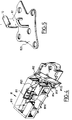
- the bridge 82 for example in the form of a half-ring, is mounted on a plate 820 which comprises the fixed part 72 of the security 70, as illustrated for example in FIG. 5.
- the body 81 is preferably provided with a lug 801 bent fixing which is intended to cooperate with the semi-fixed element 312 of the slide, as well as holes intended to receive fixing means such as screws or rivets.
- an improved seat according to the invention are, for example, made of mechanically welded metal parts as is conventional.
- the body and the stopper of the safety device are, for example, made of suitable synthetic materials such as a molded resin as is conventional.
- the handle located at the front end of the control bar is usually grasped and lifted.
- the lock which normally immobilizes the two elements of the slide (s) and also on the lock which is used for anchoring to the buckle of the seat belt to secure it to the floor.
- Latch and lock are thus neutralized against their particular elastic stresses and we can then slide the seat on its slides, forward or backward, to place it in the desired position.
- the blocking of the seat in the new desired position and the securing of the seat belt buckle are then done, conversely, either automatically or only when the handle is released.
- the choice of the front end of the translational travel of the seat is preferably retained for reasons of saving space and swept volume when the seat is tilted, taking into account the useful interior dimensions of the vehicle cabin.
- one of the slides can be relocked while remaining at the front end of its travel, while another is re-locked in a position which is no longer that of this front end of the travel. .
- a similar situation can occur if the two slides are relocked in a position which is neither of them this front end of the travel of translation. At the end of tilting, the seat is no longer found against the floor in its normal support conditions. Indeed, only the two cooperating parts with conjugate profiles of the safety located on the side of a slide which is at the front end of its travel of translation, can escape one from the other whereas these same parts of another or slides which are locked for a position which is not this front end of the translation travel, abut one against the other.
- the seat or the seat takes “left” as well in its plan as in the plane propeller under its own weight and this left is accentuated during the occupation of the seat.
- the seat or the seat does not normally rest on the floor but remains at a distance from it, the cooperating parts with conjugate profiles of the safety bearing on one another by the arches of their respective J .
- the consequence of this warping and / or false support is that the bolt of the lock may not be reset in the keeper, fixed to the latter.
- the buckle of the seat belt anchored to the strike is therefore not really moored to the floor. We therefore understand that if under these conditions a passenger in the rear seat buckle up, he believes he is really protected in the event of a shock when this is only a deceptive appearance.
- the invention remedies this type of dysfunction.
- the seat in this situation rests on the floor directly by its slides or indirectly through the bodies of the safety device which serve to 'spacers, and the lyre-shaped clamp located in the housing closes elastically on the trigger guard secured to the floor, which it traps. This ensures a certain centering, positioning and small immobilization of the slides relative to the floor.
- the lock box used to anchor a seat belt buckle is secured to the bolt secured to the floor.
- the seat can only be folded down when it has been pushed back completely to the front end of its translation travel.
- the invention prohibits accidental adjustment during the tilting phase, whether it is to retract the seat or to return it to the "road” position, that is to say as soon as the clamps associated with the slides have left their centering bridges. This is achieved by the tilting cleat biased by its return spring.
- the cleat feeler rests against the trigger guard and causes the cleat to tip into a retracted or inactive position. In this position, the stop of the cleat is not facing the retainer integral with the seat and, more particularly, with the movable element of the slide. We can then slide at will by translation the seat to communicate the desired position as previously indicated.
- the retainer which cooperates with the retractable stop of the cleat is constituted by the tip 83 or a part which is close thereto, of the movable element 71 of the safety 70 It is clear that any other member integral or integrated with the movable element of the slide or with the frame of the seat can be used.
- the invention applies to two sliding members relative to one another and the assembly of the two of which is pivotally mounted relative to a bearing surface.
- the invention realizes in an extremely simple manner the blocking of these two members with respect to each other in a single given position and this immediately as soon as the assembly begins to tilt after leaving its bearing surface.
- the invention operates in the manner of the logical "OR" function. Indeed, either we can slide the two bodies relative to each other but we cannot tilt them as a whole except for a single relative longitudinal position, for example the position "all the front ", or else we can tilt the two parts as a whole but we cannot slide them one with respect to the other except for a single angular position: the support position.
- the first prohibition is obtained by the interlocking of the two parts with combined profiles of the safety and the second prohibition by the engagement of the stop and the stop of the device.
Description
La présente invention concerne les sièges pour véhicules automobiles terrestres et, plus particulièrement, les sièges réglables et basculables destinés à être montés sur le plancher du véhicule.The present invention relates to seats for land motor vehicles and, more particularly, adjustable and tiltable seats intended to be mounted on the vehicle floor.
Comme on le sait, les sièges pour véhicules automobiles terrestres se composent notamment d'une assise à laquelle est associé un dossier. La construction d'un tel siège est telle que, le plus souvent, le dossier est inclinable relativement à l'assise voire rabattable contre cette dernière, selon une direction orthogonale à l'axe longitudinal du véhicule. De plus, le siège dans son ensemble est le plus souvent réglable en translation selon une direction parallèle à l'axe longitudinal du véhicule et en outre, s'il y a lieu, ce siège dans son exemple, habituellement après rabattement du dossier contre son assise, est aussi basculable selon une direction qui est orthogonale à l'axe longitudinal du véhicule. Une telle configuration est adoptée parfois pour les sièges avant en particulier pour les véhicules dits coupés afin de faciliter l'accès aux places des sièges arrière ou bien aussi pour les sièges arrière afin de dégager un complément de volume permettant de charger des objets encombrants. C'est le cas par exemple des véhicules dits trois portes ou cinq portes qui permettent de transformer un véhicule dit de "tourisme ou conduite intérieure" en "break".As is known, the seats for land motor vehicles consist in particular of a seat to which is associated a backrest. The construction of such a seat is such that, most often, the backrest is tiltable relative to the seat or even foldable against the latter, in a direction orthogonal to the longitudinal axis of the vehicle. In addition, the seat as a whole is most often adjustable in translation in a direction parallel to the longitudinal axis of the vehicle and further, if necessary, this seat in its example, usually after folding the backrest against its seat, is also tiltable in a direction which is orthogonal to the longitudinal axis of the vehicle. Such a configuration is sometimes adopted for the front seats, in particular for so-called coupe vehicles in order to facilitate access to the seats in the rear seats, or also for the rear seats in order to free up additional volume enabling bulky objects to be loaded. This is the case for example of so-called three-door or five-door vehicles which make it possible to transform a so-called "touring or sedan" vehicle into a "station wagon".
Dans le cas des sièges arrière, qu'ils se présentent sous la forme de sièges individuels ou d'une banquette multiplace, la situation se complique du fait de la présence des ceintures de sécurité dont l'un des constituants de la boucle se trouve amarré au plancher pratiquement dans l'axe longitudinal médian du véhicule. En effet, dans ce cas il faut que l'amarrage au plancher de la boucle de la ceinture de sécurité puisse, à la fois, s'adapter aux diverses positions longitudinales en translation du siège et aussi permettre le basculement du siège complet après rabattement du dossier contre l'assise.In the case of rear seats, whether in the form of individual seats or a multi-seat bench, the situation is complicated by the presence of seat belts, one of the components of the buckle of which is moored to the floor practically in the median longitudinal axis of the vehicle. Indeed, in this case it is necessary that the mooring to the floor of the buckle of the seat belt can, at the same time, adapt to the various longitudinal positions in translation of the seat and also allow the tilting of the complete seat after folding the backrest against the seat.
WO 83/03081 décrit un siège du type réglable et basculable, destiné à être monté sur le plancher d'un véhicule automobile terrestre.WO 83/03081 describes a seat of the adjustable and tiltable type, intended to be mounted on the floor of a land motor vehicle.
EP-A-0 558 380, qui est compris dans l'état de la technique au sens de l'article 54(3) CBE, décrit un siège du type précité comprenant une serrure composite articulée qui permet de satisfaire à l'essentiel des contraintes contradictoires imposées précisées ci-dessus. La solution décrite par ce document permet, en outre, une adaptation automatique à l'intervalle des écarts dûs aux tolérances de fabrication notamment du plancher d'un véhicule.EP-A-0 558 380, which is included in the state of the art within the meaning of Article 54 (3) EPC, describes a seat of the aforementioned type comprising an articulated composite lock which makes it possible to satisfy most of the contradictory constraints imposed specified above. The solution described by this document also allows automatic adaptation to the interval of deviations due to manufacturing tolerances, in particular of the floor of a vehicle.
Toutefois, une difficulté subsiste encore lorsqu'après avoir été basculé en totalité pour gagner de la place, un siège arrière est redéployé en position "route" apte à être occupé par un occupant et repose en principe contre le plancher du véhicule. En effet, lorsqu'un utilisateur saisit le siège pour le faire basculer en position d'utilisation ou "route" depuis l'arrière du véhicule non seulement il fait décrire un arc de cercle à l'assise contre laquelle est replié le dossier mais il tend aussi à modifier la position longitudinale en translation de l'ensemble du siège relativement au plancher. Dans une telle situation, du fait notamment que la rigidité de l'assise, et en particulier de son armature mécano-soudée, n'est pas absolument parfaite, celle-ci tend à prendre du gauche aussi bien dans son plan en se transformant approximativement en parallélogramme que dans l'espace en se transformant "en hélice d'avion", l'un des côtés de l'armature portant par exemple contre un appui du plancher qui n'est pas le symétrique de l'appui du côté opposé. Dans un tel cas, le siège repose de guingois sur le plancher, et si un occupant y prend place et boucle sa ceinture de sécurité il peut se faire que la serrure à laquelle l'un des constituants de la boucle est ancré ne soit pas réellement et efficacement amarrée au plancher, le siège "boîtant" sur ce dernier. On imagine facilement que si dans une telle situation une brusque décélération survient, que ce soit par suite d'un freinage brutal ou d'un choc violent, le passager qui se croyait protégé n'est plus retenu par sa ceinture de sécurité et est projeté vers l'avant du véhicule.However, a difficulty still remains when, after having been completely tilted to save space, a rear seat is redeployed in the "road" position capable of being occupied by an occupant and rests in principle against the floor of the vehicle. In fact, when a user grasps the seat to tilt it into the use or "road" position from the rear of the vehicle, not only does it describe an arc of a circle at the seat against which the backrest is folded, but it also tends to modify the longitudinal position in translation of the entire seat relative to the floor. In such a situation, in particular because the rigidity of the seat, and in particular of its mechanically welded frame, is not absolutely perfect, it tends to take the left as well in its plane by transforming approximately in parallelogram than in space by transforming "into an airplane propeller", one of the sides of the frame bearing for example against a support of the floor which is not the symmetrical of the support on the opposite side. In such a case, the seat is lopsided on the floor, and if an occupant takes a seat in it and fastens their seatbelt, it may happen that the lock to which one of the constituents of the buckle is anchored is not actually and effectively moored to the floor, the seat "limping" on the latter. We can easily imagine that if in such a situation a sudden deceleration occurs, whether as a result of brutal braking or a violent shock, the passenger who thought he was protected is no longer retained by his seat belt and is thrown towards the front of the vehicle.
Une situation similaire peut aussi se produire sans que l'assise se gauchisse réellement si l'armature, bien qu'en appui symétrique, ne repose pas réellement sur les parties qui lui sont assignées du plancher mais en demeure insidieusement à distance sans que cela soit réellement perceptible.A similar situation can also occur without the seat actually warping if the reinforcement, although in symmetrical support, does not really rest on the parts assigned to it of the floor but remains insidiously at a distance without it being really noticeable.
Le but de l'invention est de remédier à ce type d'inconvénient nuisible à la sécurité à l'aide d'un siège perfectionné, réglable et basculable, destiné à être monté sur le plancher d'un véhicule automobile terrestre.The object of the invention is to remedy this type of disadvantage detrimental to safety using an improved seat, adjustable and tiltable, intended to be mounted on the floor of a land motor vehicle.
A cet effet, l'invention a pour objet un siège du type réglable et basculable, destiné à être monté sur le plancher d'un véhicule automobile terrestre, comprenant une assise réglable en translation selon une direction parallèle à l'axe longitudinal du véhicule avec une course limitée par deux positions d'extrémités et basculable en rotation selon une direction orthogonale à cet axe longitudinal, un dossier porté par l'assise et rabattable sur cette dernière par rotation selon une direction orthogonale à cet axe longitudinal, au moins un montage avec, d'une part, une glissière permettant cette translation et faite d'un élément mobile solidaire de l'assise et d'un élément semi-fixe coopérant avec l'élément mobile et destiné à être relié au plancher et avec, d'autre part, une articulation permettant ce basculement et reliant cet élément semi-fixe au plancher, un verrou pour maintenir normalement immobilisés relativement l'un à l'autre les éléments de la glissière sous l'action d'une sollicitation élastique, une serrure pour normalement interdire ce basculement, qui est faite d'une gâche solidaire du plancher et d'un pêne articulé coopérant avec cette gâche pour s'y fixer automatiquement sous l'action d'une sollicitation élastique et qui sert à l'ancrage d'au moins une boucle de ceinture de sécurité pour son amarrage au plancher, une commande pour agir sur ces verrou et serrure à l'encontre de leurs sollicitations élastiques particulières afin de permettre à volonté ces translation et/ou basculement, et un dispositif de sûreté suppléant temporairement le verrou auquel il se substitue momentanément, ce dispositif de sûreté comprenant, d'une part, porté par l'assise un corps délimitant un logement pour une pince et pour un taquet mobile entre une première position active où il immobilise et condamne la glissière lorsque le siège occupe l'une des extrémités de sa course de translation et une seconde position inactive où il laisse libre la glissière, lorsque le siège n'occupe pas cette extrémité de sa translation, et, d'autre part, porté par le plancher un pontet destiné à coopérer avec cette pince et ce taquet.To this end, the subject of the invention is a seat of the adjustable and tiltable type, intended to be mounted on the floor of a land motor vehicle, comprising a seat adjustable in translation in a direction parallel to the longitudinal axis of the vehicle with a stroke limited by two end positions and tiltable in rotation in a direction orthogonal to this longitudinal axis, a backrest carried by the seat and foldable on the latter by rotation in a direction orthogonal to this longitudinal axis, at least one mounting with on the one hand, a slide allowing this translation and made of a movable element secured to the seat and of a semi-fixed element cooperating with the movable element and intended to be connected to the floor and with, on the other hand, an articulation allowing this tilting and connecting this semi-fixed element to the floor, a bolt to keep immobilized relatively to each other the elements of the slide under the action of an elastic stress, a lock to normally prohibit this tilting, which is made of a keeper secured to the floor and an articulated bolt cooperating with this keeper to fix it automatically under the action of an elastic stress and which is used for anchoring at least one seat belt buckle for its mooring on the floor, a command to act on these latch and lock against their particular elastic stresses in order to allow these translation and / or tilting at will, and an alternate safety device temporarily the bolt which it temporarily replaces, this safety device comprising, on the one hand, carried by the seat a body delimiting a housing for a clamp and for a cleat movable between a first active position where it immobilizes and condemns the slide when the seat occupies one of the ends of its translation travel and a second inactive position where it leaves the slide free, when the seat does not occupy this end of its translation, and, on the other hand, carried by the floor a trigger guard intended to cooperate with this clamp and this cleat.
Un tel siège est aussi remarquable en ce qu'il comprend, s'il y a lieu et de préférence, une sécurité faite de deux parties coopérantes à profils conjugués l'une mobile solidaire de l'assise et l'autre fixe solidaire du plancher et agencées pour autoriser seulement lorsque le siège est à cette extrémité de sa course de translation soit le basculement du siège dans un sens après séparation du pêne d'avec la gâche soit la fixation du pêne à la gâche après basculement du siège dans le sens opposé.Such a seat is also remarkable in that it includes, if necessary and preferably, a safety made of two cooperating parts with conjugate profiles, one movable secured to the seat and the other fixed secured to the floor. and arranged to authorize only when the seat is at this end of its translational travel, ie the tilting of the seat in one direction after separation of the bolt from the strike or the fixing of the bolt to the strike after tilting of the seat in the opposite direction.
L'invention a aussi pour objet l'application d'un tel siège perfectionné à un siège arrière mono ou multiplace.The invention also relates to the application of such an improved seat to a single or multi-seat rear seat.
D'autres caractéristiques de l'invention ressortiront de la lecture de la description et des revendications qui suivent ainsi que de l'examen du dessin annexé, donné seulement à titre d'exemple, où :
- la Figure 1 est une vue perspective schématique d'un mode de réalisation d'un siège perfectionné selon l'invention;
- la Figure 2 est une vue partielle schématique, en élévation latérale, du siège de la Figure 1;
- la Figure 3 est une vue analogue à celle de la Figure 2, partiellement en coupe selon un plan longitudinal médian vertical;
- la Figure 4 est une vue de détail d'un constituant d'un dispositif de sûreté d'un siège selon l'invention;
- la Figure 5 est une vue de détail, partielle d'autres constituants de la sécurité et du dispositif de sûreté d'un siège selon l'invention; et
- la Figure 6 est une vue de détail, partielle montrant la sécurité et le dispositif de sûreté.
- Figure 1 is a schematic perspective view of an embodiment of an improved seat according to the invention;
- Figure 2 is a schematic partial view, in side elevation, of the seat of Figure 1;
- Figure 3 is a view similar to that of Figure 2, partially in section along a vertical median longitudinal plane;
- Figure 4 is a detail view of a component of a seat safety device according to the invention;
- Figure 5 is a detail view, partial of other safety components and the safety device of a seat according to the invention; and
- Figure 6 is a detail view, partial showing the security and the safety device.
Les sièges pour véhicules et tout spécialement pour véhicules automobiles terrestres étant bien connus dans la technique, on ne décrira dans ce qui suit que ce qui concerne directement ou indirectement l'invention. Pour le surplus, l'Homme du Métier du secteur technique considéré puisera dans les solutions classiques courantes à sa disposition pour faire face aux problèmes particuliers auxquels il est confronté.As the seats for vehicles and especially for land motor vehicles are well known in the art, the following will only describe what relates directly or indirectly to the invention. For the rest, the skilled person in the technical sector considered will draw on the current conventional solutions at his disposal to deal with the particular problems with which he is confronted.
Dans ce qui suit, on utilise toujours un même numéro de référence pour identifier un élément homologue, quel que soit le mode de réalisation ou sa variante d'exécution.In what follows, the same reference number is always used to identify a homologous element, whatever the embodiment or its variant of execution.
Pour la commodité de l'exposé, on décrira successivement chacun des constituants d'un siège perfectionné selon l'invention avant d'en indiquer la fabrication au besoin, et le fonctionnement.For the convenience of the description, each of the constituents of an improved seat according to the invention will be described successively before indicating the manufacturing as required, and operation.
Dans la suite, on décrit un siège perfectionné réglable et basculable selon l'invention dans son application spécifique à un siège arrière dont l'assise est faite d'une banquette à deux places et dont le dossier est fait de deux dossiers indépendants éventuellement réglables en inclinaison et/ou séparément rabattables l'un de l'autre sur l'assise.In the following, an improved adjustable and tiltable seat according to the invention is described in its specific application to a rear seat whose seat is made of a two-seater bench seat and whose backrest is made of two independent backrests possibly adjustable in tilt and / or separately foldable from each other on the seat.
Comme on le voit, un siège 10 perfectionné réglable et basculable selon l'invention comprend une assise 11 et un dossier 12 destinés à être montés sur un plancher 20 d'un véhicule, un montage 30, un verrou 40, une serrure 50, une commande 60, de préférence une sécurité 70 et un dispositif de sûreté 80.As can be seen, an improved adjustable and
L'assise 11, faite d'une armature le plus souvent mécano-soudée de tout type classique comme illustré par exemple, est destinée à porter un coussin non représenté. Cette assise est réglable en translation selon une direction parallèle à l'axe X longitudinal du véhicule avec une course limitée par deux positions extrêmes. Cette assise est aussi basculable en rotation selon une direction Y orthogonale à cet axe longitudinal X comme illustré. Le dossier 12 à inclinaison réglable s'il y a lieu, est porté par l'assise et est rabattable sur cette dernière par rotation selon une direction orthogonale à l'axe longitudinal X. Ce dossier est fait d'une armature habituellement mécano-soudée comme illustré de tout type classique, qui est destinée à porter un coussin non illustré. La direction de rabattement est définie par une articulation de tout type approprié classique, d'axe 100.The
Ce siège est destiné à être monté sur le plancher 20 ou similaire d'un véhicule automobile qui présente une surface d'appui 21. Pour ce faire, on utilise le montage 30 qui comprend, d'une part, au moins une glissière 31 permettant la translation parallèlement à l'axe X. Cette glissière 31 comprend un élément 311 mobile solidaire de l'assise 11, et un élément 312 semi-fixe coopérant avec l'élément mobile 311 et destiné à être relié au plancher 20. Les glissières de ce type sont bien connues dans la technique et l'on ne s'y étendra pas davantage. Le montage 30 comprend aussi une articulation 32 telle une charnière ou analogue d'axe 320 permettant le basculement selon une direction orthogonale à l'axe X. Cette charnière relie l'élément semi-fixe 312 au plancher 20. Cette charnière, de tout type approprié classique, est clairement représentée sur les figures du dessin. Habituellement on utilise au moins deux glissières et deux charnières, une à droite et une à gauche du siège.This seat is intended to be mounted on the
Le verrou 40 maintient normalement immobilisés relativement l'un à l'autre les éléments 311 et 312 de la glissière 31 sous l'action d'une sollicitation élastique appropriée. Ce verrou est par exemple fait de dents et de crans s'engageant les uns dans les autres, comme il est connu. Pour permettre un réglage en translation de l'ensemble du siège par rapport au plancher on agit à l'encontre de la sollicitation élastique exercée par exemple par une lame ressort ou similaire afin de neutraliser le verrou, par exemple par dégagement des dents d'avec les crans et ainsi pouvoir faire coulisser le siège dans la position souhaitée, par exemple pour gagner du volume de rangement à l'arrière du dossier au détriment de la place disponible pour les jambes des passagers qui occupent les sièges arrière ou inversement. Ceci est classique.The
La serrure 50 qui sert à l'ancrage d'au moins une boucle de ceinture de sécurité et à son amarrage au plancher interdit aussi, normalement, le basculement du siège et tout spécialement de l'assise par rotation selon la charnière, de préférence après rabattement du ou des dossiers contre l'assise. Cette serrure comprend une gâche 51 solidaire du plancher et faite, par exemple, d'au moins un barreau transversal, et un pêne 52 composite articulé avec un coffre à débattement pourvu d'un crochet mobile. Le pêne 52 est destiné à coopérer avec la gâche 51 et à s'y fixer automatiquement sous l'action d'une sollicitation élastique tout en pouvant à volonté s'en séparer pour permettre le basculement du siège. Une tige 53 ou similaire permet l'ancrage d'au moins une boucle de ceinture de sécurité par l'intermédiaire du pédoncule ou similaire de cette dernière, comme il est classique. Cette serrure est par exemple du type de celle décrite dans le document cité précédemment auquel on pourra utilement se reporter pour plus ample information.The
La commande 60 permet d'agir sur le verrou 40 et/ou la serrure 50 à l'encontre de leurs sollicitations élastiques particulières afin de permettre, à volonté, d'opérer le réglage en translation et/ou autoriser le basculement. Cette commande se présente par exemple à la manière d'une barre 61 apte à basculer relativement au plancher selon un axe 600 qui est orthogonal à l'axe X et est situé entre ses extrémités 62. Chacune de ces extrémités 62 qui sont situées de part et d'autre de l'assise, comme illustré, sont munies d'une poignée 621 ou similaire. Pour les raisons que l'on comprendra par la suite, une contre-poignée 63 est parfois située à proximité de la poignée 621 située à l'arrière de l'assise, comme illustré. L'écartement normal de la contre-poignée 63 et de la poignée 621 est tel qu'on peut les saisir simultanément d'une seule main pour les rapprocher l'une de l'autre, comme on le comprendra par la suite. Tout ceci apparaît clairement notamment sur la Figure 3.The
La sécurité 70 facultative comprend deux parties 71, 72 coopérantes à profils conjugués. Une 71 de ces parties est solidaire de l'assise 11 et est donc mobile avec cette dernière. Une autre 72 de ces parties est solidaire du plancher 20 et est donc fixe. La partie mobile 71 a par exemple un profil en J et la partie fixe 72 a un profil en J inversé. L'agencement de cette sécurité est tel que les deux parties 71, 72 ont les arcs de leur J respectif normalement toujours engagés l'un dans l'autre à la manière de deux crochets tête-bêche, sauf à l'une des extrémités de la course de translation du siège et, plus particulièrement, lorsque l'assise et tout ce qu'elle porte sont repoussés le plus en avant possible, repéré par rapport à l'orientation traditionnelle d'un véhicule. Ce n'est que lorsque le siège occupe cette extrémité de sa course, ici "tout à l'avant", que soit le basculement du siège dans un sens après séparation du pêne d'avec la gâche est possible soit, inversement, la fixation du pêne à la gâche après basculement du siège dans le sens opposé est possible. Dans le mode de réalisation illustré, la partie mobile 71 de la sécurité 70 est solidaire de l'élément mobile 311 de la glissière 31 et la partie fixe 72 est solidaire du plancher 20, directement ou indirectement.The
Le dispositif de sûreté 80, comme on le comprendra par la suite, supplée temporairement le verrou 40 auquel il se substitue momentanément. Ce dispositif est agencé de manière à soit, dans une première position active, immobiliser et condamner la glissière 31 lorsque le siège occupe cette extrémité de sa course de translation tout en autorisant son basculement, soit, dans une seconde position inactive, laisser libre la glissière 31 lorsque le siège n'occupe pas cette extrémité de sa course de translation, son basculement étant alors s'il y a lieu interdit par la sécurité 70. Le dispositif de sécurité 80 comprend un corps 81 porté directement ou non par l'assise 11, et un pontet 82 solidaire directement ou non du plancher 20. Le corps 81 délimite un logement 810 pour une pince 811. Cette pince 811 présente, de préférence, deux branches 8110 élastiques en forme de lyre. Le logement 810 est aussi pourvu d'un taquet 812 mobile entre une position active où il immobilise et condamne la glissière 31 et une position inactive où il laisse libre la glissière 31. Le taquet 812 se présente à la manière d'un levier monté basculant sur une goupille 813 ou similaire et est soumis au couple d'un ressort 814 qui tend normalement à le placer dans sa position active. Comme on le voit sur le dessin, le taquet 812 comprend un palpeur 8121 et une butée 8122. Le pontet 82 est destiné à coopérer avec la pince 811 et avec le taquet 812 et, plus particulièrement, son palpeur 8121. La butée 8122 est destinée à coopérer avec un arrêtoir 83 ou analogue solidaire directement ou indirectement de l'assise 11. L'arrêtoir 83 est monté directement sur l'assise ou de préférence indirectement par l'entremise de la glissière 31, notamment sur l'élément mobile 311 de cette dernière. Le pontet 82, par exemple en forme de demi-anneau, est monté sur une platine 820 qui comprend la partie fixe 72 de la sécurité 70, comme illustré par exemple sur la Figure 5. Le corps 81 est de préférence muni d'une patte de fixation 801 recourbée qui est destinée à coopérer avec l'élément semi-fixe 312 de la glissière, ainsi que de trous destinés à recevoir des moyens de fixation tels que des vis ou des rivets.The
Pratiquement tous les constituants d'un siège perfectionné selon l'invention sont, par exemple, faits de pièces métalliques mécano-soudées comme il est classique. Le corps et le taquet du dispositif de sûreté sont, par exemple, faits en matériaux synthétiques appropriés telle une résine moulée comme il est classique.Practically all the components of an improved seat according to the invention are, for example, made of mechanically welded metal parts as is conventional. The body and the stopper of the safety device are, for example, made of suitable synthetic materials such as a molded resin as is conventional.
Tous les constituants d'un siège perfectionné selon l'invention sont réunis, assemblés et montés comme cela ressort clairement de l'examen des figures du dessin et des explications qui précédent.All the components of an improved seat according to the invention are assembled, assembled and mounted as is clear from an examination of the figures of the drawing and the preceding explanations.
On exposera maintenant le fonctionnement d'un siège perfectionné selon l'invention.The operation of an improved seat according to the invention will now be explained.
On suppose que le mode de réalisation d'un tel siège est initialement dans la situation où il est illustré sur la Figure 1.It is assumed that the embodiment of such a seat is initially in the situation where it is illustrated in Figure 1.
Pour régler en translation la position longitudinale du siège selon une direction parallèle à l'axe longitudinal X du véhicule, on saisit habituellement la poignée située à l'extrémité antérieure de la barre de la commande et on la soulève. En faisant ceci, on agit simultanément sur le verrou qui immobilise normalement les deux éléments de la ou des glissières et aussi sur la serrure qui sert à l'ancrage à la boucle de la ceinture de sécurité pour l'amarrer au plancher. Verrou et serrure sont de la sorte neutralisés à l'encontre de leurs sollicitations élastiques particulières et on peut alors faire coulisser le siège sur ses glissières, vers l'avant ou vers l'arrière, pour le placer dans la position souhaitée. Le blocage du siège dans la nouvelle position recherchée et l'amarrage de la boucle de la ceinture de sécurité se font ensuite, inversement, soit automatiquement soit seulement au relâchement de la poignée. On pourra par exemple se reporter utilement au document FR 2 662 126 qui décrit une solution de ce type.To adjust the longitudinal position of the seat in translation in a direction parallel to the longitudinal axis X of the vehicle, the handle located at the front end of the control bar is usually grasped and lifted. By doing this, one acts simultaneously on the lock which normally immobilizes the two elements of the slide (s) and also on the lock which is used for anchoring to the buckle of the seat belt to secure it to the floor. Latch and lock are thus neutralized against their particular elastic stresses and we can then slide the seat on its slides, forward or backward, to place it in the desired position. The blocking of the seat in the new desired position and the securing of the seat belt buckle are then done, conversely, either automatically or only when the handle is released. We can for example usefully refer to document FR 2 662 126 which describes a solution of this type.
Si, maintenant, on souhaite basculer l'ensemble du siège, on rabat d'abord, éventuellement après déblocage comme il est classique, le dossier simple ou multiple contre l'assise en le faisant basculer selon l'axe 100. Ceci fait, on saisit habituellement ensemble la poignée et la contre-poignée situées à l'arrière du siège et on les serre simultanément pour les rapprocher l'une de l'autre. Ceci a pour effet de neutraliser simultanément le verrou des glissières et la serrure comme indiqué auparavant. D'un même geste, on peut alors à la fois repousser le siège vers une des extrémités de sa course de translation, de préférence l'extrémité avant, et soulever l'assise avec le dossier rabattu contre elle pour basculer le siège relativement au plancher en le faisant tourner sur sa charnière. Cette opération est possible pour deux raisons. La première c'est que la manoeuvre de la commande a séparé le pêne de la serrure d'avec sa gâche. La seconde, c'est que l'avancée à fond de course du siège a séparé les parties à profils conjugués de la sécurité qui ne sont plus maintenant face à face.If, now, we want to tilt the entire seat, we fold first, possibly after unlocking as it is conventional, the single or multiple backrest against the seat by tilting it along the
Le choix de l'extrémité avant de la course en translation du siège est de préférence retenu pour des raisons de gain de place et de volume balayé lors du basculement du siège, compte-tenu des dimensions intérieures utiles de l'habitacle du véhicule.The choice of the front end of the translational travel of the seat is preferably retained for reasons of saving space and swept volume when the seat is tilted, taking into account the useful interior dimensions of the vehicle cabin.
Si on souhaite remettre en place le siège qui a été ainsi replié, il suffit d'opérer en sens inverse.If you want to replace the seat that has been folded in this way, you just have to work in reverse.
Normalement il suffit de saisir la contre-poignée et d'exercer sur l'ensemble du siège un mouvement de rotation tendant à le replacer en appui contre le plancher. Cependant, il peut arriver qu'on saisisse simultanément la poignée et la contre-poignée comme indiqué auparavant, et qu'on exerce sur l'ensemble du siège un mouvement combiné de traction et de rotation, généralement depuis l'arrière du véhicule. Comme on se le rappelle, le fait de se saisir de la poignée et de la contre-poignée qui lui fait face, peut neutraliser le verrou des glissières dont l'élément mobile est susceptible de se déplacer par rapport à l'élément semi-fixe. Au cours de cette phase de basculement, les diverses glissières peuvent jouer relativement les unes aux autres, se déplacer et se reverrouiller au hasard et même dans des positions différentes, à droite et à gauche notamment pour les raisons exposées précédemment. En particulier, l'une des glissières peut se reverrouiller en étant demeurée à l'extrémité avant de sa course de translation alors qu'une autre se trouve reverrouillée dans une position qui n'est plus celle de cette extrémité avant de la course de translation. Une situation similaire peut se produire si les deux glissières se reverrouillent dans une position qui n'est pour aucune d'elles cette extrémité avant de la course de translation. En fin de basculement, le siège ne se retrouve plus alors contre le plancher dans ses conditions normales d'appui. En effet, seules les deux parties coopérantes à profils conjugués de la sécurité situées du côté d'une glissière qui est à l'extrémité avant de sa course de translation, peuvent échapper l'une à l'autre alors que ces mêmes parties d'une autre ou des glissières qui sont verrouillées pour une position qui n'est pas cette extrémité avant de la course de translation, butent l'une contre l'autre. Dans le premier cas le siège ou la banquette prend du "gauche" aussi bien dans son plan qu'en hélice d'avion sous son propre poids et ce gauche s'accentue lors de l'occupation du siège. Dans le second cas le siège ou la banquette ne repose pas normalement sur le plancher mais demeure à distance de celui-ci, les parties coopérantes à profils conjugués de la sécurité prenant appui l'une sur l'autre par les arcs de leurs J respectifs. La conséquence de ce gauchissement et/ou de ce faux appui est que le pêne de la serrure risque de ne pas être réenclenché dans la gâche, fixé à cette dernière. La boucle de la ceinture de sécurité ancrée à la gâche n'est donc pas réellement amarrée au plancher. On comprend donc que si dans ces conditions un passager du siège arrière boucle sa ceinture, il croit être réellement protégé en cas de chocs alors qu'il ne s'agit là que d'une apparence trompeuse.Normally it suffices to grasp the counter-handle and exert on the whole seat a rotational movement tending to replace it resting against the floor. However, it can happen that the handle and the counter handle are simultaneously grasped as indicated above, and that a combined movement of traction and rotation is exerted on the entire seat, generally from the rear of the vehicle. As we remember, grabbing the handle and the counter-handle facing it, can neutralize the lock of the slides, the movable element of which can move relative to the semi-fixed element . During this changeover phase, the various slides can play relatively to each other, move and relock at random and even in different positions, to the right and to the left, in particular for the reasons explained above. In particular, one of the slides can be relocked while remaining at the front end of its travel, while another is re-locked in a position which is no longer that of this front end of the travel. . A similar situation can occur if the two slides are relocked in a position which is neither of them this front end of the travel of translation. At the end of tilting, the seat is no longer found against the floor in its normal support conditions. Indeed, only the two cooperating parts with conjugate profiles of the safety located on the side of a slide which is at the front end of its travel of translation, can escape one from the other whereas these same parts of another or slides which are locked for a position which is not this front end of the translation travel, abut one against the other. In the first case, the seat or the seat takes "left" as well in its plan as in the plane propeller under its own weight and this left is accentuated during the occupation of the seat. In the second case, the seat or the seat does not normally rest on the floor but remains at a distance from it, the cooperating parts with conjugate profiles of the safety bearing on one another by the arches of their respective J . The consequence of this warping and / or false support is that the bolt of the lock may not be reset in the keeper, fixed to the latter. The buckle of the seat belt anchored to the strike is therefore not really moored to the floor. We therefore understand that if under these conditions a passenger in the rear seat buckle up, he believes he is really protected in the event of a shock when this is only a deceptive appearance.
L'invention remédie à ce type de dysfonctionnement.The invention remedies this type of dysfunction.
En effet, lorsque le siège est normalement déployé en position "route", comme illustré sur la Figure 1, le siège dans cette situation repose sur le plancher directement par ses glissières ou indirectement par l'intermédiaire des corps du dispositif de sécurité qui servent d'entretoises, et la pince en forme de lyre située dans le logement se referme élastiquement sur le pontet solidaire du plancher, qu'elle emprisonne. Ceci assure un certain centrage, une mise en place et une petite immobilisation des glissières par rapport au plancher. De même le coffre de la serrure servant à l'ancrage d'une boucle de ceinture de sécurité est arrimé au pêne solidaire du plancher. Toutefois, comme déjà indiqué, on ne peut rabattre le siège que lorsque celui-ci a été préalablement repoussé à fond à l'extrémité avant de sa course de translation. Ceci est dû à la présence de la sécurité dont les deux parties à profils conjugués, l'une liée au plancher et l'autre à l'élément mobile de la glissière, interdisent tout basculement pour une position autre que celle d'extrémité "tout à l'avant". En effet, ces parties qui coulissent réalisent un "crochetage" pour toutes les autres positions en translation du siège autres que la position d'extrémité "tout à l'avant" pour laquelle ces deux parties ne sont plus en vis-à-vis et autorisent le basculement. Ce sont ces parties qui contribuent au dysfonctionnement. En effet, comme on l'a signalé auparavant, les glissières situées de chaque côté sont susceptibles de se dérégler pendant une opération de remise en place en position "route" du siège et alors, les deux parties coopérantes de la ou des glissière(s) qui n'est (ne sont) pas restée(s) dans sa(leur) position d'extrémité "tout à l'avant", butent l'une sur l'autre, la pince solidaire de l'élément semi-fixe de la glissière ne se recentre plus sur son pontet et le pêne de la serrure ne s'amarre plus sur la gâche.Indeed, when the seat is normally deployed in the "road" position, as illustrated in Figure 1, the seat in this situation rests on the floor directly by its slides or indirectly through the bodies of the safety device which serve to 'spacers, and the lyre-shaped clamp located in the housing closes elastically on the trigger guard secured to the floor, which it traps. This ensures a certain centering, positioning and small immobilization of the slides relative to the floor. Likewise, the lock box used to anchor a seat belt buckle is secured to the bolt secured to the floor. However, as already indicated, the seat can only be folded down when it has been pushed back completely to the front end of its translation travel. This is due to the presence of safety, the two parts with conjugate profiles, one linked to the floor and the other to the movable element of the slide, prevent any tilting to a position other than that of the end "all in the front". Indeed, these sliding parts produce a "hooking" for all the other positions in translation of the seat other than the end position "all the front" for which these two parts are no longer opposite and allow switching. These are the parts that contribute to the dysfunction. Indeed, as it was pointed out before, the slides located on each side are liable to be out of adjustment during a reseating operation in the "road" position of the seat and then, the two cooperating parts of the one or more slide (s) which have not remained in its end position "all the way forward", abut one on the other, the clamp secured to the element semi-fixed slide no longer refocuses on its trigger guard and the bolt of the lock no longer moor on the keeper.
Pour remédier à cet inconvénient rédhibitoire l'invention interdit le déréglage accidentel, pendant la phase de basculement que ce soit pour escamoter le siège ou pour le replacer en position "route", c'est-à-dire aussitôt que les pinces associées aux glissières ont quitté leurs pontets de centrage. Ceci est obtenu grâce au taquet basculant sollicité par son ressort de rappel. Lorsque le siège est en position "route" correcte, comme illustré sur la Figure 1, le palpeur du taquet repose contre le pontet et fait basculer le taquet dans une position escamotée ou inactive. Dans cette position, la butée du taquet n'est pas face à l'arrêtoir solidaire de l'assise et, plus particulièrement, de l'élément mobile de la glissière. On peut alors faire coulisser à volonté par translation le siège pour lui communiquer la position recherchée comme précédemment indiqué. Par contre, si l'on a repoussé le siège à l'extrémité avant de sa course de translation et que simultanément on a commencé à le basculer comme indiqué précédemment, la pince se sépare du pontet et simultanément, le palpeur se sépare de celui-ci : sous l'action du ressort de rappel le taquet bascule et sa butée vient se mettre face à l'arrêtoir. Tout coulissement relatif de l'élément mobile par rapport à l'élément semi-fixe d'une glissière est alors entravé. Le siège est donc immobilisé et condamné en position "tout à l'avant".To overcome this unacceptable drawback, the invention prohibits accidental adjustment during the tilting phase, whether it is to retract the seat or to return it to the "road" position, that is to say as soon as the clamps associated with the slides have left their centering bridges. This is achieved by the tilting cleat biased by its return spring. When the seat is in the correct "road" position, as illustrated in Figure 1, the cleat feeler rests against the trigger guard and causes the cleat to tip into a retracted or inactive position. In this position, the stop of the cleat is not facing the retainer integral with the seat and, more particularly, with the movable element of the slide. We can then slide at will by translation the seat to communicate the desired position as previously indicated. On the other hand, if the seat has been pushed back to the front end of its translational travel and that simultaneously we have started to tilt it as indicated above, the clamp separates from the trigger guard and simultaneously, the feeler separates from it ci: under the action of the return spring, the cleat rocks and its stop comes to face the stop. Any relative sliding of the movable element relative to the semi-fixed element of a slide is then hampered. The seat is therefore immobilized and locked in the "all forward" position.
Inversement, lorsqu'on veut replacer un siège ainsi basculé en position escamotée, en position "route" la libération des deux éléments de la glissière ne se produit qu'en fin de course de basculement, lorsque le palpeur du taquet prend contact avec le pontet et fait basculer le taquet pour séparer la butée de l'arrêtoir. Cette séparation de la butée et de l'arrêtoir se produit simultanément au centrage qui résulte de la mise en prise de la pince en lyre avec le pontet lui-même.Conversely, when one wants to replace a seat thus tilted in the retracted position, in the "road" position, the release of the two elements of the slide only occurs at the end of the tilting stroke, when the cleat feeler makes contact with the trigger guard and tilts the cleat to separate the stop from the retainer. This separation of the stop and the stop occurs simultaneously with the centering which results from the engagement of the clamp in lyre with the trigger guard itself.
On est donc assuré que lorsqu'on remet le siège en position "route" les parties à profils conjugués de la sécurité ne buteront pas l'une contre l'autre et, surtout, que le pêne de la serrure sera bien fixé à la gâche pour assurer un amarrage réel au plancher de la ou des boucles de ceinture de sécurité.We are therefore assured that when we return the seat to the "road" position, the parts with combined profiles of the safety will not abut against each other and, above all, that the bolt of the lock will be well fixed to the strike. to ensure real anchoring to the floor of the seat belt buckle (s).
Dans le mode de réalisation décrit, on a fait en sorte que l'arrêtoir qui coopère avec la butée escamotable du taquet, soit constitué par le bout 83 ou une partie qui lui en est proche, de l'élément mobile 71 de la sécurité 70. Il est clair qu'on peut utiliser toute autre organe solidaire ou intégré à l'élément mobile de la glissière ou à l'armature de l'assise.In the embodiment described, it has been made so that the retainer which cooperates with the retractable stop of the cleat, is constituted by the
Autrement dit, on voit que l'invention s'applique à deux organes coulissants l'un par rapport à l'autre et dont l'ensemble des deux est monté basculant par rapport à une surface d'appui. L'invention réalise d'une manière extrêmement simple le blocage de ces deux organes l'un par rapport à l'autre dans une position donnée unique et cela immédiatement aussitôt que l'ensemble commence à basculer après avoir quitté sa surface d'appui.In other words, it can be seen that the invention applies to two sliding members relative to one another and the assembly of the two of which is pivotally mounted relative to a bearing surface. The invention realizes in an extremely simple manner the blocking of these two members with respect to each other in a single given position and this immediately as soon as the assembly begins to tilt after leaving its bearing surface.
Comme on le comprend, l'invention opère à la manière de la fonction logique "OU". En effet, ou bien on peut faire coulisser les deux organes l'un par rapport à l'autre mais on ne peut pas les faire basculer dans leur ensemble sauf pour une position longitudinale relative unique, par exemple la position "tout à l'avant", ou bien on peut faire basculer dans leur ensemble les deux organes mais on ne peut pas les faire coulisser l'un par rapport à l'autre sauf pour une position angulaire unique : la position d'appui. La première interdiction est obtenue par l'interverrouillage des deux parties à profils conjugués de la sécurité et la seconde interdiction par la mise en prise de la butée et de l'arrêtoir du dispositif.As will be understood, the invention operates in the manner of the logical "OR" function. Indeed, either we can slide the two bodies relative to each other but we cannot tilt them as a whole except for a single relative longitudinal position, for example the position "all the front ", or else we can tilt the two parts as a whole but we cannot slide them one with respect to the other except for a single angular position: the support position. The first prohibition is obtained by the interlocking of the two parts with combined profiles of the safety and the second prohibition by the engagement of the stop and the stop of the device.
Ce qui précède met bien en lumière les particularités distinctives de l'invention, montre son intérêt et fait bien ressortir les avantages qu'elle apporte.The above clearly highlights the distinctive features of the invention, shows its interest and highlights the advantages it brings.
Claims (14)
- Seat (10) of the adjustable and tiltable type, intended to be mounted on the floor (20) of a terrestrial automobile, comprisinga seat portion (11) which is adjustable in a translational direction in a direction parallel to the longitudinal axis (X) of the vehicle, with a travel limited by two extreme positions, and rotationally tiltable in a direction (Y) orthogonal to said longitudinal axis (X),a back portion (12) supported by the seat portion (11) and hinged to fold down rotationally on to the latter in a direction orthogonal to said longitudinal axis (X),at least one assembly (30) with, on the one hand, a slide (31) enabling said translational movement and made up of a mobile member (311) integral with the seat portion (11) and of a semi-fixed member (312) co-operating with the mobile member (311), and intended to be connected to the floor (20) and with, on the other hand, a joint (32) enabling this tilting movement and connecting said semi-fixed member (312) to the floor (20),a bolt (40) for keeping the members (311, 312) of the slide (31) immobile relative to one another under normal conditions, under the action of a resilient bias,a lock (50) for preventing this tilting movement under normal conditions, and being made up of a keeper (51) integral with the floor (20) and of a bolt (52) articulated to co-operate with said keeper (51), in order to be automatically fixed in that position under the effect of a resilient bias, and which serves to anchor at least one safety-belt buckle, mooring it to the floor (20),a control means (60) for acting on the said bolt (40) and lock (50) against their respective resilient bias, enabling the translational and tilting movements to be carried out at will, anda safety device (80) temporarily supplementing the bolt (40) for which it forms a temporary substitute, said safety device (80) comprising on the one hand a body (81) supported by the seat portion (11), defining a housing (810) for a pincer (811) and for a catch (812) movable between a first operative position in which it immobilises the slide (31) and, when the seat (10) occupies one of the extreme positions of its translational movement, securing said slide (31) in a second, inoperative position in which it leaves the slide (31) free, when the seat (10) does not occupy this extreme translational position, and on the other hand by a yoke (82) supported by the floor (20), intended to co-operate with said pincer (811) and said catch (812).
- Seat according to claim 1, in which the catch (812) is a lever tiltably mounted on a pin (813) and subjected to the force of a spring (814) in order normally to occupy its inoperative position.
- Seat according to claim 1 or 2, in which the catch (812) comprises a feeler (8121) intended to co-operate with the yoke (82) and a stop (8122) intended to co-operate with a stopper (83) integral with the seat (11).
- Seat according to claim 3, in which the stopper (83) is mounted directly or indirectly on the seat (11).
- Seat according to claim 4, in which the stopper (83) is mounted on the slide (31).
- Seat according to claim 4 or 5, in which the stopper (83) is integral with the mobile member (311) of the slide (31).
- Seat according to any one of claims 1 to 6, in which the body (81) is equipped with a securing tab (801) intended to co-operate with the semi-fixed member (312) of the slide (31).
- Seat according to any one of claims 1 to 7, in which the pincer (811) has two resilient lyre-shaped branches (8110) intended to bridge over the yoke (82) when the seat occupies a position in which the safety device (80) leaves the slide (31) free.
- Seat according to any one of claims 1 to 8, comprising a security element (70) made up of two co-operating portions (71,72) with connecting profiles, one (71) mobile and integral with the seat (11) and the other (72) fixed and integral with the floor (20), and set up to permit either tilting of the seat (10) in one direction after separation of the bolt (52) from the keeper (51), or fixing of the bolt (52) to the keeper (51) after tilting of the seat (10) in the opposite direction, only when the seat (10) is at this end of its translational travel.
- Seat according to claim 9, in which the security element (70) comprises a mobile portion (71) with a 'J' profile, and a fixed portion (72) with an inverted 'J' profile.
- Seat according to claim 10, in which the mobile portion (71) is integral with the mobile member (311) of the slide (31), and the fixed portion (72) is integral with the floor (20).
- Seat according to claim 10 or 11, in which the yoke (82) is mounted on a plate (820) comprising the fixed portion (72).
- Seat according to any one of claims 1 to 12, in which the end of the translational travel is that situated furthest forward.
- Application of a seat according to any one of claims 1 to 13 for a rear single- or multiple-place seat.
Applications Claiming Priority (2)
| Application Number | Priority Date | Filing Date | Title |
|---|---|---|---|
| FR9302658 | 1993-03-08 | ||
| FR9302658A FR2702428B1 (en) | 1993-03-08 | 1993-03-08 | Improved car seat and its application in particular to a rear seat. |
Publications (2)
| Publication Number | Publication Date |
|---|---|
| EP0614781A1 EP0614781A1 (en) | 1994-09-14 |
| EP0614781B1 true EP0614781B1 (en) | 1997-10-15 |
Family
ID=9444750
Family Applications (1)
| Application Number | Title | Priority Date | Filing Date |
|---|---|---|---|
| EP19940400474 Expired - Lifetime EP0614781B1 (en) | 1993-03-08 | 1994-03-04 | Vehicle seat and its application to a rear seat |
Country Status (4)
| Country | Link |
|---|---|
| EP (1) | EP0614781B1 (en) |
| DE (1) | DE69406157T2 (en) |
| ES (1) | ES2111266T3 (en) |
| FR (1) | FR2702428B1 (en) |
Cited By (1)
| Publication number | Priority date | Publication date | Assignee | Title |
|---|---|---|---|---|
| US7137667B2 (en) | 2002-12-04 | 2006-11-21 | Faurecia Autositze Gmbh & Co.Kg | Vehicle seat and its application to a rear seat |
Families Citing this family (7)
| Publication number | Priority date | Publication date | Assignee | Title |
|---|---|---|---|---|
| GB9404120D0 (en) * | 1994-03-03 | 1994-04-20 | Allied Signal Ltd | Multiposition vehicle rear seat arrangement |
| JP2002096713A (en) * | 2000-09-21 | 2002-04-02 | Honda Motor Co Ltd | Occupant protective structure of foldable seat for vehicle |
| DE102004054650B4 (en) * | 2004-11-11 | 2007-04-19 | Johnson Controls Gmbh | Hinge, in particular for a vehicle and in particular for a motor vehicle seat and seat, in particular for a motor vehicle having the rotary joint |
| DE102005009040B4 (en) * | 2005-02-22 | 2018-11-08 | Dr. Ing. H.C. F. Porsche Aktiengesellschaft | Vehicle seat with seat-length adjustment via two handles |
| FR3023223B1 (en) * | 2014-07-04 | 2016-07-15 | Renault Sa | BENCH FOR MOTOR VEHICLE AND ASSOCIATED MOUNTING METHOD |
| CN107972541B (en) | 2016-10-25 | 2022-05-31 | 福特环球技术公司 | Inclination angle adjusting mechanism for vehicle seat and vehicle rear seat |
| FR3112998B1 (en) * | 2020-07-31 | 2022-08-05 | Faurecia Sieges Dautomobile | vehicle seat |
Family Cites Families (6)
| Publication number | Priority date | Publication date | Assignee | Title |
|---|---|---|---|---|
| FR2449552A1 (en) * | 1979-02-21 | 1980-09-19 | Renault | Folding seat for car - has seat folding relative to floor and back relative to seat and has locking lever actuating retaining cam |
| BR6200272U (en) * | 1982-03-05 | 1983-10-18 | Volkswagen Brasil | REAR SEAT FOR VEHICLE |
| JPH0645322B2 (en) * | 1988-09-17 | 1994-06-15 | 池田物産株式会社 | Vehicle seat device |
| JPH0639231B2 (en) * | 1990-02-09 | 1994-05-25 | 株式会社大井製作所 | Folding seat safety device for vehicle |
| FR2662126B1 (en) * | 1990-05-16 | 1992-09-04 | Tubauto | DEVICE FOR AUTOMATICALLY HANGING TO THE FLOOR OF A VEHICLE WITH A MEANS FOR ATTACHING A SEAT BELT. |
| FR2687625B1 (en) * | 1992-02-25 | 1994-05-27 | Europ Sieges Automobiles | AUTOMATIC LOCKING LOCK FOR ANCHORING A SEAT BELT AND ITS APPLICATION TO A REAR SEAT. |
-
1993
- 1993-03-08 FR FR9302658A patent/FR2702428B1/en not_active Expired - Fee Related
-
1994
- 1994-03-04 EP EP19940400474 patent/EP0614781B1/en not_active Expired - Lifetime
- 1994-03-04 DE DE1994606157 patent/DE69406157T2/en not_active Expired - Fee Related
- 1994-03-04 ES ES94400474T patent/ES2111266T3/en not_active Expired - Lifetime
Cited By (1)
| Publication number | Priority date | Publication date | Assignee | Title |
|---|---|---|---|---|
| US7137667B2 (en) | 2002-12-04 | 2006-11-21 | Faurecia Autositze Gmbh & Co.Kg | Vehicle seat and its application to a rear seat |
Also Published As
| Publication number | Publication date |
|---|---|
| DE69406157T2 (en) | 1998-02-26 |
| DE69406157D1 (en) | 1997-11-20 |
| FR2702428A1 (en) | 1994-09-16 |
| EP0614781A1 (en) | 1994-09-14 |
| ES2111266T3 (en) | 1998-03-01 |
| FR2702428B1 (en) | 1995-07-07 |
Similar Documents
| Publication | Publication Date | Title |
|---|---|---|
| EP0798154B1 (en) | Slide for vehicle seat and seat with such a slide | |
| EP1894771B1 (en) | Automotive seat for a child pivotable between a use position and at least one access position, with a trigger | |
| EP1697160B1 (en) | Seat for an Aircraft | |
| FR2870795A1 (en) | VEHICLE SEAT AND VEHICLE EQUIPPED WITH SUCH A SEAT | |
| FR2851211A1 (en) | Vehicle seat, has backrest rotatably mounted in accordance with rail and seat having interlocking device to selectively authorize rotation of backrest, and front with upper and lower end is rotatably mounted based on vehicle floor | |
| EP3060428B1 (en) | Device for locking a folding element in position for a vehicle seat | |
| EP0381559A1 (en) | Inclinable and collapsible seat back | |
| FR2880308A1 (en) | HEAD SUPPORT FOR A MOTOR VEHICLE SEAT | |
| EP0683066B1 (en) | Memory lock slide, in particular for vehicle seats | |
| WO2002008013A1 (en) | Child safety device adaptable on a vehicle | |
| FR2841838A1 (en) | VEHICLE SEAT HAVING A JOINT MECHANISM | |
| EP0614781B1 (en) | Vehicle seat and its application to a rear seat | |
| EP0659607B1 (en) | Articulation with backlash elimination for seat with tilting backrest | |
| EP0627337B1 (en) | Seat for motor vehicles | |
| EP2137026B1 (en) | Seat for automobile convertible into child seat with the back facing road and related automobile | |
| FR2772319A1 (en) | Vehicle seat, folds flat to vehicle floor, | |
| EP0402195B1 (en) | Demountable fastening device for the rear seat of a motor vehicle | |
| EP0373081B1 (en) | Collapsible seat especially for the equipment of automotive vehicles | |
| FR2707934A1 (en) | Improved seat for a motor vehicle adaptable to the morphology of the occupant | |
| FR2463024A1 (en) | Rear seat vehicle belt for folding seat - has floor mounting on safety catch to release belt | |
| EP0558375A1 (en) | Seat for motor vehicles | |
| EP0558380B1 (en) | Automatic engaging lock for a seat belt anchor and its application to a vehicle's rear seat | |
| FR2863560A1 (en) | Rear seat for e.g. minibus, has angle unit joined to base and strut connector of support, such that support and base are concurrently rotated in opposite directions, where base and backrest rotates in vehicle movement direction to fold base | |
| FR3012383A1 (en) | RETRACTABLE SEAT FOR VEHICLE | |
| FR2897565A1 (en) | Vehicle`s e.g. motor vehicle, foldable front/back seat, has base pivotally mounted on support surface around joint pin to pass base from horizontal position to storage vertical position in which seat forms vertical wall |
Legal Events
| Date | Code | Title | Description |
|---|---|---|---|
| PUAI | Public reference made under article 153(3) epc to a published international application that has entered the european phase |
Free format text: ORIGINAL CODE: 0009012 |
|
| 17P | Request for examination filed |
Effective date: 19940616 |
|
| AK | Designated contracting states |
Kind code of ref document: A1 Designated state(s): DE ES GB IT |
|
| 17Q | First examination report despatched |
Effective date: 19961008 |
|
| GRAG | Despatch of communication of intention to grant |
Free format text: ORIGINAL CODE: EPIDOS AGRA |
|
| GRAH | Despatch of communication of intention to grant a patent |
Free format text: ORIGINAL CODE: EPIDOS IGRA |
|
| GRAH | Despatch of communication of intention to grant a patent |
Free format text: ORIGINAL CODE: EPIDOS IGRA |
|
| GRAA | (expected) grant |
Free format text: ORIGINAL CODE: 0009210 |
|
| AK | Designated contracting states |
Kind code of ref document: B1 Designated state(s): DE ES GB IT |
|
| ITF | It: translation for a ep patent filed |
Owner name: BUGNION S.P.A. |
|
| GBT | Gb: translation of ep patent filed (gb section 77(6)(a)/1977) |
Effective date: 19971017 |
|
| REF | Corresponds to: |
Ref document number: 69406157 Country of ref document: DE Date of ref document: 19971120 |
|
| PGFP | Annual fee paid to national office [announced via postgrant information from national office to epo] |
Ref country code: GB Payment date: 19980224 Year of fee payment: 5 |
|
| REG | Reference to a national code |
Ref country code: ES Ref legal event code: FG2A Ref document number: 2111266 Country of ref document: ES Kind code of ref document: T3 |
|
| PLBE | No opposition filed within time limit |
Free format text: ORIGINAL CODE: 0009261 |
|
| STAA | Information on the status of an ep patent application or granted ep patent |
Free format text: STATUS: NO OPPOSITION FILED WITHIN TIME LIMIT |
|
| 26N | No opposition filed | ||
| PG25 | Lapsed in a contracting state [announced via postgrant information from national office to epo] |
Ref country code: GB Free format text: LAPSE BECAUSE OF NON-PAYMENT OF DUE FEES Effective date: 19990304 |
|
| GBPC | Gb: european patent ceased through non-payment of renewal fee |
Effective date: 19990304 |
|
| PG25 | Lapsed in a contracting state [announced via postgrant information from national office to epo] |
Ref country code: IT Free format text: LAPSE BECAUSE OF NON-PAYMENT OF DUE FEES;WARNING: LAPSES OF ITALIAN PATENTS WITH EFFECTIVE DATE BEFORE 2007 MAY HAVE OCCURRED AT ANY TIME BEFORE 2007. THE CORRECT EFFECTIVE DATE MAY BE DIFFERENT FROM THE ONE RECORDED. Effective date: 20050304 |
|
| PGFP | Annual fee paid to national office [announced via postgrant information from national office to epo] |
Ref country code: DE Payment date: 20060227 Year of fee payment: 13 |
|
| PGFP | Annual fee paid to national office [announced via postgrant information from national office to epo] |
Ref country code: ES Payment date: 20060309 Year of fee payment: 13 |
|
| PG25 | Lapsed in a contracting state [announced via postgrant information from national office to epo] |
Ref country code: DE Free format text: LAPSE BECAUSE OF NON-PAYMENT OF DUE FEES Effective date: 20071002 |
|
| REG | Reference to a national code |
Ref country code: ES Ref legal event code: FD2A Effective date: 20070305 |
|
| PG25 | Lapsed in a contracting state [announced via postgrant information from national office to epo] |
Ref country code: ES Free format text: LAPSE BECAUSE OF NON-PAYMENT OF DUE FEES Effective date: 20070305 |