EP0614176A1 - Optical disk reproducing method and apparatus - Google Patents
Optical disk reproducing method and apparatus Download PDFInfo
- Publication number
- EP0614176A1 EP0614176A1 EP94301451A EP94301451A EP0614176A1 EP 0614176 A1 EP0614176 A1 EP 0614176A1 EP 94301451 A EP94301451 A EP 94301451A EP 94301451 A EP94301451 A EP 94301451A EP 0614176 A1 EP0614176 A1 EP 0614176A1
- Authority
- EP
- European Patent Office
- Prior art keywords
- optical disk
- reproduction beam
- reproduction
- condensing
- light
- Prior art date
- Legal status (The legal status is an assumption and is not a legal conclusion. Google has not performed a legal analysis and makes no representation as to the accuracy of the status listed.)
- Granted
Links
Images


Classifications
-
- G—PHYSICS
- G11—INFORMATION STORAGE
- G11B—INFORMATION STORAGE BASED ON RELATIVE MOVEMENT BETWEEN RECORD CARRIER AND TRANSDUCER
- G11B7/00—Recording or reproducing by optical means, e.g. recording using a thermal beam of optical radiation by modifying optical properties or the physical structure, reproducing using an optical beam at lower power by sensing optical properties; Record carriers therefor
- G11B7/12—Heads, e.g. forming of the optical beam spot or modulation of the optical beam
- G11B7/125—Optical beam sources therefor, e.g. laser control circuitry specially adapted for optical storage devices; Modulators, e.g. means for controlling the size or intensity of optical spots or optical traces
- G11B7/126—Circuits, methods or arrangements for laser control or stabilisation
-
- G—PHYSICS
- G11—INFORMATION STORAGE
- G11B—INFORMATION STORAGE BASED ON RELATIVE MOVEMENT BETWEEN RECORD CARRIER AND TRANSDUCER
- G11B7/00—Recording or reproducing by optical means, e.g. recording using a thermal beam of optical radiation by modifying optical properties or the physical structure, reproducing using an optical beam at lower power by sensing optical properties; Record carriers therefor
- G11B7/004—Recording, reproducing or erasing methods; Read, write or erase circuits therefor
- G11B7/005—Reproducing
Definitions
- the present invention relates to an optical disk reproducing method and apparatus.
- Information is recorded by, e.g., utilizing three-dimensional patterns formed on a substrate or reflectance difference caused due to a phase change between crystal and amorphous phases, or by forming a recording layer consisting of a magnetic film on a substrate to record information by difference in direction of magnetization, thereby forming a recording mark.
- a laser beam is generally used to reproduce the recording marks.
- the laser beam is formed to be a spot as small as the diffraction limit defined by the wavelength of the laser beam to read the phase shape of the disk, the reflectance difference, rotation of the polarized light caused due to the magnetooptical effect of the magnetic film or the like. Because of the noise of the apparatus, a better S/N ratio can be obtained by increasing the reproduction light amount.
- information is recorded by heat using optical energy. Therefore, when the information on the medium is to be reproduced, the power must be controlled not to destroy the information by the reproduction beam.
- a multilayered structure of magnetic layers is formed to utilize magnetic super resolution due to heat of the reproduction beam, thereby reading high-density-recorded marks (MORIS' 91, 18-I-06).
- MORIS' 91, 18-I-06 high-density-recorded marks
- An object of the present invention is to solve the above problems posed in the conventional optical disk reproducing apparatus.
- an optical disk reproducing method using an optical disk reproducing apparatus comprising an optical disk, optical disk rotating means, a light source for irradiating a reproduction beam on the optical disk, light condensing means for condensing the reproduction beam on the optical disk, detection means for detecting a beam passing through or reflected by the optical disk, and position detection means for detecting a reproduction beam condensing position in a radial direction on the optical disk, wherein an intensity of the reproduction beam is changed in accordance with the reproduction beam condensing position on the optical disk.
- an optical disk reproducing method using an optical disk reproducing apparatus comprising an optical disk, optical disk rotating means, a light source for irradiating a reproduction beam on the optical disk, light condensing means for condensing the reproduction beam on the optical disk, detection means for detecting a beam passing through or reflected by the optical disk, and position detection means for detecting a reproduction beam condensing position in a radial direction on the optical disk, wherein an intensity of the reproduction beam in reproduction of an outer region of the disk is set to be larger than that in reproduction of an inner region of the optical disk.
- an optical disk reproducing method using an optical disk reproducing apparatus comprising an optical disk, optical disk rotating means, a light source for irradiating a reproduction beam on the optical disk, light condensing means for condensing the reproduction beam on the optical disk, detection means for detecting a beam passing through or reflected by the optical disk, and position detection means for detecting a reproduction beam condensing position in a radial direction on the optical disk, wherein an intensity of the reproduction beam is changed in accordance with a linear velocity of the optical disk at the reproduction beam condensing position.
- an optical disk reproducing apparatus comprising an optical disk, optical disk rotating means, a light source for irradiating a reproduction beam on the optical disk, light condensing means for condensing the reproduction beam on the optical disk, detection means for detecting a beam passing through or reflected by the optical disk, position detection means for detecting a reproduction beam condensing position in a radial direction on the optical disk, and reproduction beam drive means for changing an intensity of the reproduction beam in accordance with the reproduction beam condensing position.
- an optical disk reproducing apparatus comprising an optical disk, optical disk rotating means, a light source for irradiating a reproduction beam on the optical disk, light condensing means for condensing the reproduction beam on the optical disk, detection means for detecting a beam passing through or reflected by the optical disk, position detection means for detecting a reproduction beam condensing position in a radial direction on the optical disk, and reproduction beam drive means for changing an intensity of the reproduction beam in accordance with a linear velocity of the optical disk at the reproduction beam condensing position.
- an optical disk reproducing method using an optical disk reproducing apparatus comprising an optical disk, optical disk rotating means, a light source for irradiating a reproduction beam on the optical disk, light condensing means for condensing the reproduction beam on the optical disk, detection means for detecting a beam passing through or reflected by the optical disk, and position detection means for detecting a reproduction beam condensing position in a radial direction on the optical disk, wherein an intensity of the reproduction beam is changed in accordance with a linear velocity of the optical disk at the reproduction beam condensing position so that a substantially constant medium temperature is obtained at a reproduction beam irradiation portion of the optical disk.
- an optical disk reproducing apparatus comprising an optical disk, optical disk rotating means, a light source for irradiating a reproduction beam on the optical disk, light condensing means for condensing the reproduction beam on the optical disk, detection means for detecting a beam passing through or reflected by the optical disk, position detection means for detecting a reproduction beam condensing position in a radial direction on the optical disk, and reproduction beam drive means for changing an intensity of the reproduction beam in accordance with a linear velosity of the optical disk at the reproduction beam condensing position so that a substantially constant medium temperature is obtained at a reproduction beam irradiation portion of the optical disk.
- the intensity of the reproduction beam may be changed stepwise from the inner side to the outer side of the optical disk, or it may be linearly, curvilinearly, or polygonally changed in accordance with the linear velocity on the basis of the information recorded on the disk.
- the intensity of the reproduction beam may be changed by changing the light intensity of the reproduction light source itself, or inserting a filter between the reproduction light source and the optical disk.
- the reproducing apparatus can also be used as a recording apparatus by changing the intensity of the reproduction beam, it may also serve as a recording apparatus.
- Fig. 1 is a schematic view showing an optical disk reproducing apparatus according to an embodiment of the present invention.
- a light beam is emitted from a reproduction beam light source 13 constituted by a 780-nm semiconductor laser.
- the light beam is condensed, through a polarization beam splitter 20, onto an optical disk 11 by a light condensing means 14 for condensing a reproduction beam.
- the light condensing means 14 is arranged on a reproduction position moving means 16 for changing the beam condensing position in the radial direction.
- the light condensing means 14 is constituted by an objective lens having a numerical aperture (NA) of 0.55.
- NA numerical aperture
- the reproduction position moving means 16 is constituted by an actuator for driving the objective lens to perform focusing and tracking and a slider for moving the actuator in the radial direction to change the beam condensing position on the disk.
- the disk 11 is rotated by a DD motor 12.
- the light beam reflected by the disk 11 is incident on a light detection means 15 through the polarization beam splitter 20.
- the light detection means 15 is constituted by an analyzer, a detector and the like, for reading the reflected beam, and detects the modulated signal.
- a reproduction position detection means 17 having a linear scale for reading the disk radial position of the slider of the detects the radial position on the disk which is irradiated with the reproduction beam.
- Information representing the irradiation position of the beam is output to a calculation means 18.
- the calculation means 18 controls a laser drive circuit 19 for driving the semiconductor laser 13 on the basis of the input information to change the intensity of the reproduction beam.
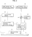
- Fig. 2 is a schematic view showing a modification of the optical disk reproducing apparatus of the above embodiment.
- information representing the rotational speed of the disk is input to the calculation means 18 from the motor 12.
- the calculation means 18 calculates the linear velocity of the optical disk at the radiation position of the beam on the basis of the information representing the radiation position of the beam (i.e., reproduction position) input from the reproduction position detection means and the information representing the rotational speed of the disk input from the motor 12.
- the calculation means 18 controls the laser drive circuit on the basis of the obtained linear velocity of the optical disk to change the intensity of the reproduction beam.
- the light condensing position on the disk is detected by the reproduction position detection means 17.
- the beam condensing position may be read out by using the detection means 15 on the basis of the information recorded on the optical disk, and the intensity of the reproduction beam may be changed by using this information.
- a magnetooptical disk was prepared, in which information had been recorded in advance by using another optical disk recording apparatus, and the recording frequency at the outer radial position was set to be twice that at the inner radial position.
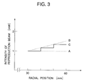
- the above optical disk was set in the reproducing apparatus of the first embodiment to perform a magnetooptical reproduction experiment. The experiment was performed by variously changing the intensity of the reproduction beam (A, B, and C in Fig. 3) in accordance with the position of the slider, as shown in Fig. 3.
- the S/N ratios at the respective radial positions are shown in Fig. 4.
- A represents the S/N ratio in the conventional irradiating method in which the intensity of the reproduction beam is not changed regardless of the irradiation position of the reproduction beam on the optical disk.
- B represents the S/N ratio in the irradiating method of the present invention in which the intensity of the reproduction beam is continuously increased as the irradiation position of the reproduction beam is moved from an inner radial position to an outer radial position of the optical disk.
- C represents the S/N ratio in the radiating method of the present invention in which the intensity of the reproduction beam is increased stepwise.
- the S/N ratio of the reproduction signal represented by A of the conventional irradiating method is degraded from an inner radial position to an outer radial position of the optical disk.
- the S/N ratios exhibit a predetermined value from an inner radial position to an outer radial position without being degraded.
- a magnetooptical disk using magnetic super resolution (MSR) was prepared. Information had been recorded in advance in all recording tracks of this disk by using another optical disk recording apparatus.
- MSR magnetic super resolution
- a recording mark smaller than the diameter of the irradiation spot of a reproduction beam is recorded.
- the recording mark is read and reproduced using this region of the spot.
- a recording mark smaller than the beam spot of the reproduction beam cannot be read.
- a recording mark smaller than the beam spot can be read to allow high-density recording.
- the above magnetooptical disk was set in the reproducing apparatus of the first embodiment to perform a reproduction experiment.
- the experiment was performed by variously changing the intensity of the reproduction beam in accordance with the position of the slider, as shown in Fig. 5.
- the C/N ratios at the respective radial positions are shown in Fig. 6.
- A represents the C/N ratio in the conventional radiating method
- B and C represent the C/N ratios in the radiating methods of the present invention.
- FIG. 5 Each reproduction beam radiating method shown in Fig. 5 is the same as in Fig. 3 of the second embodiment.
- the C/N ratio represented by A of the conventional radiating method is greatly degraded from an inner diameter position to an outer diameter position of the optical disk.
- the C/N ratios have a tendency to increase rather than to degrade from an inner diameter position to an outer diameter position of the optical disk.
- a high S/N ratio can be obtained even in a wider frequency band at the outer peripheral portion.
- a constant medium temperature of the optical disk can be obtained regardless of various linear velocities, even in a CAV (constant angular velocity) format which conventionally had a demerit of a small memory capacity per track (the memory capacity per track is defined by the number of recordable marks in the innermost peripheral region in the recording region of an optical disk). Therefore, a small mark can be read out regardless of the radial position of the reproduction beam on the optical disk while reducing the jitter.
Abstract
Description
- The present invention relates to an optical disk reproducing method and apparatus.
- Recently, an effort has been made to develop an optical recording/reproducing method which meets various demands such as a high density, a large capacity, a high access speed, or a high recording/reproducing speed, and a recording/reproducing apparatus and a recording medium (disk) used for this method.
- Information is recorded by, e.g., utilizing three-dimensional patterns formed on a substrate or reflectance difference caused due to a phase change between crystal and amorphous phases, or by forming a recording layer consisting of a magnetic film on a substrate to record information by difference in direction of magnetization, thereby forming a recording mark.
- A laser beam is generally used to reproduce the recording marks. The laser beam is formed to be a spot as small as the diffraction limit defined by the wavelength of the laser beam to read the phase shape of the disk, the reflectance difference, rotation of the polarized light caused due to the magnetooptical effect of the magnetic film or the like. Because of the noise of the apparatus, a better S/N ratio can be obtained by increasing the reproduction light amount. On the other hand, in a rewritable optical disk, information is recorded by heat using optical energy. Therefore, when the information on the medium is to be reproduced, the power must be controlled not to destroy the information by the reproduction beam.
- In recent years, an information recording method which changes the recording frequency in accordance with the radial position on the disk to realize higher-density recording has been proposed. However, when the recording frequency is changed in accordance with the radial position on the disk, the recording frequency at the outer peripheral portion is increased to broaden the reproduction frequency band at the outer peripheral portion. For this reason, the S/N ratio at the outer peripheral portion is degraded as compared to that at the inner portion.
- In another information reproducing method, a multilayered structure of magnetic layers is formed to utilize magnetic super resolution due to heat of the reproduction beam, thereby reading high-density-recorded marks (MORIS' 91, 18-I-06). However, in the above method, the medium temperature at the reproduction position must be within a predetermined range. Even in one disk, the temperature is increased by the reproduction beam in a different way depending on the rotational speed or linear velocity. Therefore, the above method can be hardly realized.
- An object of the present invention is to solve the above problems posed in the conventional optical disk reproducing apparatus.
- As a result of extensive studies of the present inventor, a novel optical disk reproducing method and apparatus have been invented.
- According to the first aspect of the present invention, there is provided an optical disk reproducing method using an optical disk reproducing apparatus comprising an optical disk, optical disk rotating means, a light source for irradiating a reproduction beam on the optical disk, light condensing means for condensing the reproduction beam on the optical disk, detection means for detecting a beam passing through or reflected by the optical disk, and position detection means for detecting a reproduction beam condensing position in a radial direction on the optical disk, wherein an intensity of the reproduction beam is changed in accordance with the reproduction beam condensing position on the optical disk.
- According to the second aspect of the present invention, there is provided an optical disk reproducing method using an optical disk reproducing apparatus comprising an optical disk, optical disk rotating means, a light source for irradiating a reproduction beam on the optical disk, light condensing means for condensing the reproduction beam on the optical disk, detection means for detecting a beam passing through or reflected by the optical disk, and position detection means for detecting a reproduction beam condensing position in a radial direction on the optical disk, wherein an intensity of the reproduction beam in reproduction of an outer region of the disk is set to be larger than that in reproduction of an inner region of the optical disk.
- According to the third aspect of the present invention, there is provided an optical disk reproducing method using an optical disk reproducing apparatus comprising an optical disk, optical disk rotating means, a light source for irradiating a reproduction beam on the optical disk, light condensing means for condensing the reproduction beam on the optical disk, detection means for detecting a beam passing through or reflected by the optical disk, and position detection means for detecting a reproduction beam condensing position in a radial direction on the optical disk, wherein an intensity of the reproduction beam is changed in accordance with a linear velocity of the optical disk at the reproduction beam condensing position.
- According to the fourth aspect of the present invention, there is provided an optical disk reproducing apparatus comprising an optical disk, optical disk rotating means, a light source for irradiating a reproduction beam on the optical disk, light condensing means for condensing the reproduction beam on the optical disk, detection means for detecting a beam passing through or reflected by the optical disk, position detection means for detecting a reproduction beam condensing position in a radial direction on the optical disk, and reproduction beam drive means for changing an intensity of the reproduction beam in accordance with the reproduction beam condensing position.
- According to the fifth aspect of the present invention, there is provided an optical disk reproducing apparatus comprising an optical disk, optical disk rotating means, a light source for irradiating a reproduction beam on the optical disk, light condensing means for condensing the reproduction beam on the optical disk, detection means for detecting a beam passing through or reflected by the optical disk, position detection means for detecting a reproduction beam condensing position in a radial direction on the optical disk, and reproduction beam drive means for changing an intensity of the reproduction beam in accordance with a linear velocity of the optical disk at the reproduction beam condensing position.
- According to the sixth aspect of the present invention, there is provided an optical disk reproducing method using an optical disk reproducing apparatus comprising an optical disk, optical disk rotating means, a light source for irradiating a reproduction beam on the optical disk, light condensing means for condensing the reproduction beam on the optical disk, detection means for detecting a beam passing through or reflected by the optical disk, and position detection means for detecting a reproduction beam condensing position in a radial direction on the optical disk, wherein an intensity of the reproduction beam is changed in accordance with a linear velocity of the optical disk at the reproduction beam condensing position so that a substantially constant medium temperature is obtained at a reproduction beam irradiation portion of the optical disk.
- According to the seventh aspect of the present invention, there is provided an optical disk reproducing apparatus comprising an optical disk, optical disk rotating means, a light source for irradiating a reproduction beam on the optical disk, light condensing means for condensing the reproduction beam on the optical disk, detection means for detecting a beam passing through or reflected by the optical disk, position detection means for detecting a reproduction beam condensing position in a radial direction on the optical disk, and reproduction beam drive means for changing an intensity of the reproduction beam in accordance with a linear velosity of the optical disk at the reproduction beam condensing position so that a substantially constant medium temperature is obtained at a reproduction beam irradiation portion of the optical disk.
- In the above methods and apparatuses, the intensity of the reproduction beam may be changed stepwise from the inner side to the outer side of the optical disk, or it may be linearly, curvilinearly, or polygonally changed in accordance with the linear velocity on the basis of the information recorded on the disk.
- The intensity of the reproduction beam may be changed by changing the light intensity of the reproduction light source itself, or inserting a filter between the reproduction light source and the optical disk.
- Furthermore, since the reproducing apparatus can also be used as a recording apparatus by changing the intensity of the reproduction beam, it may also serve as a recording apparatus.
- Although the present invention will be described in detail below with reference to its preferred embodiments, the present invention is not limited to these specific embodiments.
-
- Fig. 1 is a schematic view showing the arrangement of a reproducing apparatus according to the first embodiment of the present invention;
- Fig. 2 is a view showing a modification of the apparatus of the first embodiment;
- Fig. 3 is a graph showing the intensity of a reproduction beam as a function of the radial position in a reproduction experiment according to the second embodiment of the present invention;
- Fig. 4 is a graph showing the S/N ratio as a function of the radial position in the reproduction experiment according to the second embodiment of the present invention;
- Fig. 5 is a graph showing the intensity of the reproduction beam as a function of the radial position in a reproduction experiment according to the third embodiment of the present invention; and
- Fig. 6 is a graph showing the C/N ratio as a function of the radial position in the reproduction experiment according to the third embodiment of the present invention.
-
- Fig. 1 is a schematic view showing an optical disk reproducing apparatus according to an embodiment of the present invention. A light beam is emitted from a reproduction
beam light source 13 constituted by a 780-nm semiconductor laser. The light beam is condensed, through apolarization beam splitter 20, onto anoptical disk 11 by a light condensing means 14 for condensing a reproduction beam. The light condensing means 14 is arranged on a reproduction position moving means 16 for changing the beam condensing position in the radial direction. Specifically, the light condensing means 14 is constituted by an objective lens having a numerical aperture (NA) of 0.55. The reproduction position moving means 16 is constituted by an actuator for driving the objective lens to perform focusing and tracking and a slider for moving the actuator in the radial direction to change the beam condensing position on the disk. Thedisk 11 is rotated by aDD motor 12. The light beam reflected by thedisk 11 is incident on a light detection means 15 through thepolarization beam splitter 20. The light detection means 15 is constituted by an analyzer, a detector and the like, for reading the reflected beam, and detects the modulated signal. In this apparatus, a reproduction position detection means 17 having a linear scale for reading the disk radial position of the slider of the detects the radial position on the disk which is irradiated with the reproduction beam. Information representing the irradiation position of the beam is output to a calculation means 18. The calculation means 18 controls alaser drive circuit 19 for driving thesemiconductor laser 13 on the basis of the input information to change the intensity of the reproduction beam. - Fig. 2 is a schematic view showing a modification of the optical disk reproducing apparatus of the above embodiment. Although the modified apparatus has almost the same arrangement as in the above embodiment, in this case, information representing the rotational speed of the disk is input to the calculation means 18 from the
motor 12. The calculation means 18 calculates the linear velocity of the optical disk at the radiation position of the beam on the basis of the information representing the radiation position of the beam (i.e., reproduction position) input from the reproduction position detection means and the information representing the rotational speed of the disk input from themotor 12. The calculation means 18 controls the laser drive circuit on the basis of the obtained linear velocity of the optical disk to change the intensity of the reproduction beam. - In the above apparatuses, the light condensing position on the disk is detected by the reproduction position detection means 17. However, the beam condensing position may be read out by using the detection means 15 on the basis of the information recorded on the optical disk, and the intensity of the reproduction beam may be changed by using this information.
- A magnetooptical disk was prepared, in which information had been recorded in advance by using another optical disk recording apparatus, and the recording frequency at the outer radial position was set to be twice that at the inner radial position. The above optical disk was set in the reproducing apparatus of the first embodiment to perform a magnetooptical reproduction experiment. The experiment was performed by variously changing the intensity of the reproduction beam (A, B, and C in Fig. 3) in accordance with the position of the slider, as shown in Fig. 3. The S/N ratios at the respective radial positions are shown in Fig. 4. A represents the S/N ratio in the conventional irradiating method in which the intensity of the reproduction beam is not changed regardless of the irradiation position of the reproduction beam on the optical disk. B represents the S/N ratio in the irradiating method of the present invention in which the intensity of the reproduction beam is continuously increased as the irradiation position of the reproduction beam is moved from an inner radial position to an outer radial position of the optical disk. C represents the S/N ratio in the radiating method of the present invention in which the intensity of the reproduction beam is increased stepwise.
- Referring to Fig. 4 showing the changes in the S/N ratios of the reproduction signals at the respective radial positions, the S/N ratio of the reproduction signal represented by A of the conventional irradiating method is degraded from an inner radial position to an outer radial position of the optical disk. To the contrary, in the cases of B and C of the irradiating methods of the present invention, the S/N ratios exhibit a predetermined value from an inner radial position to an outer radial position without being degraded.
- A magnetooptical disk using magnetic super resolution (MSR) was prepared. Information had been recorded in advance in all recording tracks of this disk by using another optical disk recording apparatus. In the MSR, a recording mark smaller than the diameter of the irradiation spot of a reproduction beam is recorded. By utilizing the fact that the temperature in a trailing region of the irradiation spot on the rotating optical disk is higher than that of the other portions by a heat accumulation effect, the recording mark is read and reproduced using this region of the spot. Conventionally, a recording mark smaller than the beam spot of the reproduction beam cannot be read. In an optical disk using the MSR, however, a recording mark smaller than the beam spot can be read to allow high-density recording.
- The above magnetooptical disk was set in the reproducing apparatus of the first embodiment to perform a reproduction experiment. The experiment was performed by variously changing the intensity of the reproduction beam in accordance with the position of the slider, as shown in Fig. 5. The C/N ratios at the respective radial positions are shown in Fig. 6. As in the second embodiment, A represents the C/N ratio in the conventional radiating method, and B and C represent the C/N ratios in the radiating methods of the present invention.
- Each reproduction beam radiating method shown in Fig. 5 is the same as in Fig. 3 of the second embodiment.
- Referring to Fig. 6 showing the changes in the C/N ratios of the reproduction signals at the respective radial positions, the C/N ratio represented by A of the conventional radiating method is greatly degraded from an inner diameter position to an outer diameter position of the optical disk. To the contrary, in the cases of B and C of the radiating methods of the present invention, the C/N ratios have a tendency to increase rather than to degrade from an inner diameter position to an outer diameter position of the optical disk.
- As described above, according to the present invention, a high S/N ratio can be obtained even in a wider frequency band at the outer peripheral portion. In an optical disk using MRS which allows high-density recording, a constant medium temperature of the optical disk can be obtained regardless of various linear velocities, even in a CAV (constant angular velocity) format which conventionally had a demerit of a small memory capacity per track (the memory capacity per track is defined by the number of recordable marks in the innermost peripheral region in the recording region of an optical disk). Therefore, a small mark can be read out regardless of the radial position of the reproduction beam on the optical disk while reducing the jitter.
Claims (9)
- An optical disk reproducing method using an optical disk reproducing apparatus comprising an optical disk, optical disk rotating means, a light source for irradiating a reproduction beam on the optical disk, light condensing means for condensing the reproduction beam on the optical disk, detection means for detecting a beam passing through or reflected by the optical disk, and position detection means for detecting a reproduction beam condensing position in a radial direction on the optical disk, wherein an intensity of the reproduction beam is changed in accordance with the reproduction beam condensing position on the optical disk.
- An optical disk reproducing method using an optical disk reproducing apparatus comprising an optical disk, optical disk rotating means, a light source for irradiating a reproduction beam on the optical disk, light condensing means for condensing the reproduction beam on the optical disk, detection means for detecting a beam passing through or reflected by the optical disk, and position detection means for detecting a reproduction beam condensing position in a radial direction on the optical disk, wherein an intensity of the reproduction beam in reproduction of an outer region of the disk is set to be larger than that in reproduction of an inner region of the optical disk.
- An optical disk reproducing method using an optical disk reproducing apparatus comprising an optical disk, optical disk rotating means, a light source for irradiating a reproduction beam on the optical disk, light condensing means for condensing the reproduction beam on the optical disk, detection means for detecting a beam passing through or reflected by the optical disk, and position detection means for detecting a reproduction beam condensing position in a radial direction on the optical disk, wherein an intensity of the reproduction beam is changed in accordance with a linear velocity of the optical disk at the reproduction beam condensing position.
- An optical disk reproducing apparatus comprising an optical disk, optical disk rotating means, a light source for irradiating a reproduction beam on the optical disk, light condensing means for condensing the reproduction beam on the optical disk, detection means for detecting a beam passing through or reflected by the optical disk, position detection means for detecting a reproduction beam condensing position in a radial direction on the optical disk, and reproduction beam drive means for changing an intensity of the reproduction beam in accordance with the reproduction beam condensing position.
- An optical disk reproducing apparatus comprising an optical disk, optical disk rotating means, a light source for irradiating a reproduction beam on the optical disk, light condensing means for condensing the reproduction beam on the optical disk, detection means for detecting a beam passing through or reflected by the optical disk, position detection means for detecting a reproduction beam condensing position in a radial direction on the optical disk, and reproduction beam drive means for changing an intensity of the reproduction beam in accordance with a linear velocity of the optical disk at the reproduction beam condensing position.
- An optical disk reproducing method using an optical disk reproducing apparatus comprising an optical disk, optical disk rotating means, a light source for irradiating a reproduction beam on the optical disk, light condensing means for condensing the reproduction beam on the optical disk, detection means for detecting a beam passing through or reflected by the optical disk, and position detection means for detecting a reproduction beam condensing position in a radial direction on the optical disk, wherein an intensity of the reproduction beam is changed in accordance with a linear velocity of the optical disk at the reproduction beam condensing position so that a substantially constant medium temperature is obtained at a reproduction beam irradiation portion of the optical disk.
- An optical disk reproducing apparatus comprising an optical disk, optical disk rotating means, a light source for irradiating a reproduction beam on the optical disk, light condensing means for condensing the reproduction beam on the optical disk, detection means for detecting a beam passing through or reflected by the optical disk, position detection means for detecting a reproduction beam condensing position in a radial direction on the optical disk, and reproduction beam drive means for changing an intensity of the reproduction beam in accordance with a linear velocity of the optical disk at the reproduction beam condensing position so that a substantially constant medium temperature is obtained at a reproduction beam irradiation portion of the optical disk.
- A method of reproducing information from an optical media comprising:
scanning a surface of the media with a beam of light and detecting one or more characteristic of light reflected by or transmitted through the media,
characterised by varying the intensity of the beam of light in dependence upon the speed at which the surface of the media is scanned by the beam of light. - A method of recording information on an optical media comprising:
scanning a surface of the media with a beam of light and modulating the intensity of the light according to said information,
characterised by scaling the intensity of the modulated beam of light in dependence upon the speed at which the media is scanned by the beam of light.
Applications Claiming Priority (3)
| Application Number | Priority Date | Filing Date | Title |
|---|---|---|---|
| JP4347693 | 1993-03-04 | ||
| JP43476/93 | 1993-03-04 | ||
| JP5043476A JPH06259799A (en) | 1993-03-04 | 1993-03-04 | Method and device for reproducing optical disk |
Publications (2)
| Publication Number | Publication Date |
|---|---|
| EP0614176A1 true EP0614176A1 (en) | 1994-09-07 |
| EP0614176B1 EP0614176B1 (en) | 1999-06-16 |
Family
ID=12664777
Family Applications (1)
| Application Number | Title | Priority Date | Filing Date |
|---|---|---|---|
| EP94301451A Revoked EP0614176B1 (en) | 1993-03-04 | 1994-03-01 | Optical disk reproducing method and apparatus |
Country Status (4)
| Country | Link |
|---|---|
| US (1) | US5467337A (en) |
| EP (1) | EP0614176B1 (en) |
| JP (1) | JPH06259799A (en) |
| DE (1) | DE69419048T2 (en) |
Cited By (2)
| Publication number | Priority date | Publication date | Assignee | Title |
|---|---|---|---|---|
| EP0833312A1 (en) * | 1996-09-30 | 1998-04-01 | Nikon Corporation | Information reproduction device and method |
| EP1936611A1 (en) * | 2005-10-04 | 2008-06-25 | Matsushita Electric Industrial Co., Ltd. | Optical disc drive device and optical disc reproduction method using same |
Families Citing this family (6)
| Publication number | Priority date | Publication date | Assignee | Title |
|---|---|---|---|---|
| JP3333613B2 (en) * | 1993-12-07 | 2002-10-15 | 株式会社日立製作所 | Optical information recording medium, optical information recording / reproducing method, and optical information recording / reproducing apparatus |
| US5586099A (en) * | 1995-05-22 | 1996-12-17 | International Business Machines Corporation | Optimized laser read power based upon scan speed of optical medium and erasure characteristics of the medium |
| US20050137566A1 (en) | 2003-12-23 | 2005-06-23 | Fowles Thomas A. | Sliding reconstitution device for a diluent container |
| JP2003099948A (en) * | 2001-09-27 | 2003-04-04 | Tdk Corp | Optical recording medium, method for reproducing optical recording medium, and optical recording medium reproducing apparatus |
| JP4219108B2 (en) * | 2002-01-23 | 2009-02-04 | 三洋電機株式会社 | Disk unit |
| US7641851B2 (en) | 2003-12-23 | 2010-01-05 | Baxter International Inc. | Method and apparatus for validation of sterilization process |
Citations (5)
| Publication number | Priority date | Publication date | Assignee | Title |
|---|---|---|---|---|
| DE2753195A1 (en) * | 1976-11-30 | 1978-06-29 | Sony Corp | Rotating information disc playback appts. |
| JPS56169233A (en) * | 1980-05-28 | 1981-12-25 | Mitsubishi Electric Corp | Reproducer for optical rotary disk |
| JPS58177534A (en) * | 1982-04-08 | 1983-10-18 | Matsushita Electric Ind Co Ltd | Optical recording device |
| JPS60251524A (en) * | 1984-05-29 | 1985-12-12 | Ricoh Co Ltd | Reproducing method of optical information recording medium |
| EP0524315A1 (en) * | 1991-02-13 | 1993-01-27 | Sony Corporation | Method for reproducing signal in optically recording medium |
Family Cites Families (4)
| Publication number | Priority date | Publication date | Assignee | Title |
|---|---|---|---|---|
| JPS5369006A (en) * | 1976-11-30 | 1978-06-20 | Sony Corp | Reproducer of disc form signal recording media |
| KR970002341B1 (en) * | 1987-11-30 | 1997-03-03 | 소니 가부시끼가이샤 | Method for reproducing signal from magneto-optical |
| JP2602314B2 (en) * | 1989-02-17 | 1997-04-23 | 株式会社日立製作所 | Laser beam overwriting method for phase change optical disk and apparatus for phase change optical disk using the same |
| JPH0589465A (en) * | 1991-06-28 | 1993-04-09 | Hitachi Ltd | Method and device for optical information recording and reproduction |
-
1993
- 1993-03-04 JP JP5043476A patent/JPH06259799A/en active Pending
-
1994
- 1994-03-01 EP EP94301451A patent/EP0614176B1/en not_active Revoked
- 1994-03-01 DE DE69419048T patent/DE69419048T2/en not_active Expired - Fee Related
- 1994-03-02 US US08/204,609 patent/US5467337A/en not_active Expired - Fee Related
Patent Citations (5)
| Publication number | Priority date | Publication date | Assignee | Title |
|---|---|---|---|---|
| DE2753195A1 (en) * | 1976-11-30 | 1978-06-29 | Sony Corp | Rotating information disc playback appts. |
| JPS56169233A (en) * | 1980-05-28 | 1981-12-25 | Mitsubishi Electric Corp | Reproducer for optical rotary disk |
| JPS58177534A (en) * | 1982-04-08 | 1983-10-18 | Matsushita Electric Ind Co Ltd | Optical recording device |
| JPS60251524A (en) * | 1984-05-29 | 1985-12-12 | Ricoh Co Ltd | Reproducing method of optical information recording medium |
| EP0524315A1 (en) * | 1991-02-13 | 1993-01-27 | Sony Corporation | Method for reproducing signal in optically recording medium |
Non-Patent Citations (3)
| Title |
|---|
| PATENT ABSTRACTS OF JAPAN vol. 10, no. 124 (P - 454)<2181> 9 May 1986 (1986-05-09) * |
| PATENT ABSTRACTS OF JAPAN vol. 6, no. 59 (P - 110)<937> 16 April 1982 (1982-04-16) * |
| PATENT ABSTRACTS OF JAPAN vol. 8, no. 18 (P - 250)<1455> 26 January 1984 (1984-01-26) * |
Cited By (5)
| Publication number | Priority date | Publication date | Assignee | Title |
|---|---|---|---|---|
| EP0833312A1 (en) * | 1996-09-30 | 1998-04-01 | Nikon Corporation | Information reproduction device and method |
| EP1936611A1 (en) * | 2005-10-04 | 2008-06-25 | Matsushita Electric Industrial Co., Ltd. | Optical disc drive device and optical disc reproduction method using same |
| EP1936611A4 (en) * | 2005-10-04 | 2008-11-26 | Panasonic Corp | Optical disc drive device and optical disc reproduction method using same |
| CN101283408B (en) * | 2005-10-04 | 2011-01-05 | 松下电器产业株式会社 | Optical disc drive device and optical disc reproduction method using same |
| US8111599B2 (en) | 2005-10-04 | 2012-02-07 | Panasonic Corporation | Optical disc drive apparatus and optical disc reproduction method using the same |
Also Published As
| Publication number | Publication date |
|---|---|
| EP0614176B1 (en) | 1999-06-16 |
| DE69419048T2 (en) | 2000-01-27 |
| DE69419048D1 (en) | 1999-07-22 |
| US5467337A (en) | 1995-11-14 |
| JPH06259799A (en) | 1994-09-16 |
Similar Documents
| Publication | Publication Date | Title |
|---|---|---|
| US4985881A (en) | Record carrier for a magneto-optical disc memory having guide grooves of a plurality of tracks disposed with a predetermined relation to light spot diameter | |
| JPH056590A (en) | Magneto-optical recorder | |
| US6104686A (en) | Copy protection marks on a transparent layer of an optical disk indicating that the disk has been previously accessed | |
| EP1341167B1 (en) | Optical recording medium and optical disk device | |
| US6965545B2 (en) | Optical recording medium with prepit regions and recording/reproducing method thereof | |
| KR20050054990A (en) | High track density super resolution mo-rom medium | |
| KR100377980B1 (en) | Magneto-optical head device having integrated auxiliary lens and magnetic reproducing haed and recording and reproducing device using magneto-optical head device | |
| WO1998015949A1 (en) | Recording medium and information recorder/reproducer | |
| EP0614176B1 (en) | Optical disk reproducing method and apparatus | |
| JPH08321045A (en) | Optical disk device | |
| JPH07192287A (en) | Optical pickup device | |
| US6985428B2 (en) | Optical recording medium, recording, and reproduction apparatus having multiple recording capacity features | |
| US6021109A (en) | Optical recording medium | |
| US6115330A (en) | Optical information storage unit for recording and/or reproducing information on both the lands and the grooves of an optical medium | |
| JPS6113458A (en) | Optical information recording medium and cutting device | |
| US6147952A (en) | Optical disk apparatus for reproducing information from an optical recording medium | |
| JPH0877640A (en) | High density information recording/reproducing method | |
| EP0751505A2 (en) | Optical information-recording medium | |
| WO1995026548A1 (en) | High density information recording and reproducing method | |
| JPH09204700A (en) | Magnetooptic recording medium | |
| KR100317766B1 (en) | High Density Information Recording and Playback Method | |
| JP3138650B2 (en) | Optical disc reproducing method and recording method, and optical disc apparatus | |
| EP0555037B1 (en) | Magneto-optical information recording/reproducing apparatus | |
| JPH04319531A (en) | Optical information reproducing method and optical information recording medium | |
| JP3071677B2 (en) | Optical disk medium and its recording / reproducing device |
Legal Events
| Date | Code | Title | Description |
|---|---|---|---|
| PUAI | Public reference made under article 153(3) epc to a published international application that has entered the european phase |
Free format text: ORIGINAL CODE: 0009012 |
|
| AK | Designated contracting states |
Kind code of ref document: A1 Designated state(s): DE FR GB IT |
|
| 17P | Request for examination filed |
Effective date: 19950127 |
|
| 17Q | First examination report despatched |
Effective date: 19970620 |
|
| GRAG | Despatch of communication of intention to grant |
Free format text: ORIGINAL CODE: EPIDOS AGRA |
|
| GRAG | Despatch of communication of intention to grant |
Free format text: ORIGINAL CODE: EPIDOS AGRA |
|
| GRAG | Despatch of communication of intention to grant |
Free format text: ORIGINAL CODE: EPIDOS AGRA |
|
| GRAH | Despatch of communication of intention to grant a patent |
Free format text: ORIGINAL CODE: EPIDOS IGRA |
|
| GRAH | Despatch of communication of intention to grant a patent |
Free format text: ORIGINAL CODE: EPIDOS IGRA |
|
| GRAA | (expected) grant |
Free format text: ORIGINAL CODE: 0009210 |
|
| AK | Designated contracting states |
Kind code of ref document: B1 Designated state(s): DE FR GB IT |
|
| REF | Corresponds to: |
Ref document number: 69419048 Country of ref document: DE Date of ref document: 19990722 |
|
| ET | Fr: translation filed | ||
| ITF | It: translation for a ep patent filed |
Owner name: SOCIETA' ITALIANA BREVETTI S.P.A. |
|
| PLBQ | Unpublished change to opponent data |
Free format text: ORIGINAL CODE: EPIDOS OPPO |
|
| PLBI | Opposition filed |
Free format text: ORIGINAL CODE: 0009260 |
|
| PLBF | Reply of patent proprietor to notice(s) of opposition |
Free format text: ORIGINAL CODE: EPIDOS OBSO |
|
| 26 | Opposition filed |
Opponent name: KONINKLIJKE PHILIPS ELECTRONICS N.V. Effective date: 20000315 |
|
| PLBF | Reply of patent proprietor to notice(s) of opposition |
Free format text: ORIGINAL CODE: EPIDOS OBSO |
|
| REG | Reference to a national code |
Ref country code: GB Ref legal event code: IF02 |
|
| PGFP | Annual fee paid to national office [announced via postgrant information from national office to epo] |
Ref country code: GB Payment date: 20020227 Year of fee payment: 9 |
|
| PGFP | Annual fee paid to national office [announced via postgrant information from national office to epo] |
Ref country code: FR Payment date: 20020312 Year of fee payment: 9 |
|
| PGFP | Annual fee paid to national office [announced via postgrant information from national office to epo] |
Ref country code: DE Payment date: 20020314 Year of fee payment: 9 |
|
| PLAW | Interlocutory decision in opposition |
Free format text: ORIGINAL CODE: EPIDOS IDOP |
|
| PLAW | Interlocutory decision in opposition |
Free format text: ORIGINAL CODE: EPIDOS IDOP |
|
| PG25 | Lapsed in a contracting state [announced via postgrant information from national office to epo] |
Ref country code: GB Free format text: LAPSE BECAUSE OF NON-PAYMENT OF DUE FEES Effective date: 20030301 |
|
| PG25 | Lapsed in a contracting state [announced via postgrant information from national office to epo] |
Ref country code: DE Free format text: LAPSE BECAUSE OF NON-PAYMENT OF DUE FEES Effective date: 20031001 |
|
| GBPC | Gb: european patent ceased through non-payment of renewal fee | ||
| PG25 | Lapsed in a contracting state [announced via postgrant information from national office to epo] |
Ref country code: FR Free format text: LAPSE BECAUSE OF NON-PAYMENT OF DUE FEES Effective date: 20031127 |
|
| REG | Reference to a national code |
Ref country code: FR Ref legal event code: ST |
|
| RDAF | Communication despatched that patent is revoked |
Free format text: ORIGINAL CODE: EPIDOSNREV1 |
|
| PLBQ | Unpublished change to opponent data |
Free format text: ORIGINAL CODE: EPIDOS OPPO |
|
| PLAB | Opposition data, opponent's data or that of the opponent's representative modified |
Free format text: ORIGINAL CODE: 0009299OPPO |
|
| R26 | Opposition filed (corrected) |
Opponent name: KONINKLIJKE PHILIPS ELECTRONICS N.V. Effective date: 20000315 |
|
| RDAG | Patent revoked |
Free format text: ORIGINAL CODE: 0009271 |
|
| STAA | Information on the status of an ep patent application or granted ep patent |
Free format text: STATUS: PATENT REVOKED |
|
| 27W | Patent revoked |
Effective date: 20040812 |