EP0613703A1 - Improved attachment means for a boot to a snowshoe - Google Patents
Improved attachment means for a boot to a snowshoe Download PDFInfo
- Publication number
- EP0613703A1 EP0613703A1 EP94410013A EP94410013A EP0613703A1 EP 0613703 A1 EP0613703 A1 EP 0613703A1 EP 94410013 A EP94410013 A EP 94410013A EP 94410013 A EP94410013 A EP 94410013A EP 0613703 A1 EP0613703 A1 EP 0613703A1
- Authority
- EP
- European Patent Office
- Prior art keywords
- axis
- snowshoe
- binding
- plane
- snowshoe according
- Prior art date
- Legal status (The legal status is an assumption and is not a legal conclusion. Google has not performed a legal analysis and makes no representation as to the accuracy of the status listed.)
- Granted
Links
Images


Classifications
-
- A—HUMAN NECESSITIES
- A63—SPORTS; GAMES; AMUSEMENTS
- A63C—SKATES; SKIS; ROLLER SKATES; DESIGN OR LAYOUT OF COURTS, RINKS OR THE LIKE
- A63C13/00—Snow shoes
- A63C13/006—Shoe support thereof, e.g. plate, movable relative to the frame
-
- A—HUMAN NECESSITIES
- A63—SPORTS; GAMES; AMUSEMENTS
- A63C—SKATES; SKIS; ROLLER SKATES; DESIGN OR LAYOUT OF COURTS, RINKS OR THE LIKE
- A63C13/00—Snow shoes
- A63C13/001—Bindings therefor
-
- A—HUMAN NECESSITIES
- A63—SPORTS; GAMES; AMUSEMENTS
- A63C—SKATES; SKIS; ROLLER SKATES; DESIGN OR LAYOUT OF COURTS, RINKS OR THE LIKE
- A63C13/00—Snow shoes
- A63C13/005—Frames therefor
Definitions
- the present invention relates to a snowshoe and more particularly to an improvement in the binding of the boot which improves performance and comfort.
- Snowshoes have been known for many years because they have been used for centuries by the Scandinavian populations to travel on snow. Until today, snowshoes were used for utility or military purposes to allow the populations and the Alpine troops to move on snow for their displacements necessary for the daily life. Currently, snowshoes are rather used by sportsmen who go for hikes and walks, or even competitions. But the sportsmen, although practicing for their pleasure, are more and more demanding for the material which they use, and it is true that the products currently sold do not give complete satisfaction, and in particular during the progression on packed snow, hard or icy, as well as on a side course on a slope.
- the snowshoe comprising a sieve carrying a fixing intended to receive the shoe of the user, is characterized in that said fixing is connected to said sieve so as to be able to pivot laterally about a longitudinal axis .
- the longitudinal axis is arranged in the general plane of symmetry of the racket, while in another arrangement, it is at an angle with respect thereto.
- the attachment is linked to a support articulated on the screen around the longitudinal axis, and according to a preferred arrangement, said support is a support frame whose two side walls are such that their lower edges project under the lower surface of the racket.
- the fixing is arranged pivoting upwards relative to the support around a transverse axis, which is located above said longitudinal axis.
- the transverse axis is disposed above the upper surface of the racket, while the longitudinal axis is disposed below this surface.
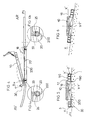
- Figure 1 is a top view of the snowshoe according to the invention.
- Figure 2 is a side view.
- Figure 3 is a perspective view schematically illustrating the racket with its articulation system.
- Figure 4 is a side view with partial longitudinal section.
- Figure 5 is a sectional view along V-V of Figure 2, the racket being supported on a horizontal snow plane.
- Figure 6 is a view similar to that of Figure 5 showing the racket resting on a slope.
- FIGS 7 and 8 are perspective views showing details of the attachment.
- FIGS 9 and 10 illustrate two other embodiments.
- the racket designated under the general reference (1) is in the form of an openwork plate of general plane of symmetry (P) fixed under the shoe and which consists of a main frame (2), consisting of a part peripheral (3) delimiting an interior zone (4), comprising a set of internal walls supporting the binding (5) intended to retain the shoe (6) of the user.
- Said main frame has a generally elongated shape extending at the rear by a tail (7) of reduced width, while the front is raised and of substantially pointed shape to constitute the front spatula (8).
- the binding (5) for retaining the shoe (6) is according to the invention articulated with respect to the frame (2) of the racket itself, along two axes, a first axis, called the transverse axis (XX ') and a second axis, called the longitudinal axis (YY ').
- said binding bearing the general reference (5) is constituted by an articulated plate (10) comprising retaining means for the shoe, namely front means (11) and rear means (12).
- the front end (60) of the shoe is retained by a front stirrup (110), while its rear end (61) is, thanks to a pivoting rear stirrup (120) comprising a lever (121) of detention.
- the plate (10) is advantageously rigid and extends longitudinally, comprising an upper bearing surface (13) for supporting the sole of the shoe.
- the position of the rear bracket (120) is adjustable thanks to a succession of lateral hooking holes (15).
- the fine adjustment allowing a perfect adaptation to the length of the shoe, is ensured by two lateral nuts (16a, 16b) arranged on the tie rods of the rear caliper.
- the transverse axis (XX ') is disposed above the longitudinal axis (YY'), said transverse axis (XX ') being, in the rest position, perpendicular to the plane of general symmetry (P) , while said longitudinal axis (YY ') is in turn located in said plane (P).
- the transverse axis (XX ') is also disposed slightly above the upper general plane (90) of the screen (4), while the longitudinal axis (YY') is disposed slightly below said plane (90).
- the plate (10) can pivot relative to the racket itself, vertically along R1 and R2 and laterally along R3 and R4.
- the central part of the screen (4) comprises a central hole (17) extending longitudinally and in which takes place a support frame (18) pivoting about the longitudinal axis (YY ').
- the central hole (17) extending forward (AV) by a front hole (170) allows the passage of the front of the plate (10) during its pivoting, as well as of the front end (60) of the shoe.
- This support (18) has the general shape of a rectangular frame bounded peripherally by two vertical side walls (19, 20) and by two vertical end walls (21, 22).
- the front end of said support frame (18) comprises two lateral projections (27, 28) extending upwards and being pierced with a hole (270, 280), intended to receive the axis (29) of the plate (10) to realize together the transverse axis (XX ') of pivoting up or down according to R1, R2.
- the axis (29) is set back behind a distance (D) from the front (30) of the shoe so that the pivot axis (XX ') is disposed at metatarsal level and thus allow better support.
- the side walls (19) and (20) have a height (H) large enough so that the lateral lower edges (190, 200) are projecting relative to the lower general support plane. (9) of the sieve (4), as appears more particularly in FIGS. 2, 4 and 5.
- the lateral lower edges (190, 200) are also projecting under the plane (P1) defined by the edge lower (30) of the wall (3) of the main frame.
Abstract
Description
La présente invention concerne une raquette à neige et plus particulièrement un perfectionnement de la liaison de la chaussure qui en améliore les performances et le confort.The present invention relates to a snowshoe and more particularly to an improvement in the binding of the boot which improves performance and comfort.
Les raquettes à neige sont des engins connus depuis de très nombreuses années car utilisées depuis plusieurs siècles par les populations Scandinaves pour se déplacer sur la neige. Jusqu'à nos jours, les raquettes à neige étaient utilisées à des fins utilitaires ou militaires pour permettre aux populations et aux troupes alpines de se déplacer sur la neige pour leurs déplacements nécessités par la vie quotidienne. Actuellement, les raquettes à neige sont plutôt utilisées par des sportifs qui font des randonnées et des promenades, voire même des compétitions. Mais les sportifs, bien que pratiquant pour leur plaisir, sont de plus en plus exigeants pour le matériel qu'ils utilisent, et il est vrai que les produits actuellement vendus ne donnent pas entière satisfaction, et notamment lors de la progression sur neige tassée, dure ou glacée, ainsi qu'en parcours latéral sur une pente.Snowshoes have been known for many years because they have been used for centuries by the Scandinavian populations to travel on snow. Until today, snowshoes were used for utility or military purposes to allow the populations and the Alpine troops to move on snow for their displacements necessary for the daily life. Currently, snowshoes are rather used by sportsmen who go for hikes and walks, or even competitions. But the sportsmen, although practicing for their pleasure, are more and more demanding for the material which they use, and it is true that the products currently sold do not give complete satisfaction, and in particular during the progression on packed snow, hard or icy, as well as on a side course on a slope.
Ainsi, selon l'invention, la raquette à neige comprenant un tamis portant une fixation destinée à recevoir la chaussure de l'utilisateur, est caractérisée en ce que ladite fixation est reliée audit tamis de façon à pouvoir pivoter latéralement autour d'un axe longitudinal.Thus, according to the invention, the snowshoe comprising a sieve carrying a fixing intended to receive the shoe of the user, is characterized in that said fixing is connected to said sieve so as to be able to pivot laterally about a longitudinal axis .
Selon une des dispositions, l'axe longitudinal est disposé dans le plan de symétrie générale de la raquette, tandis que dans une autre disposition, il est en biais par rapport à celui-ci.According to one of the arrangements, the longitudinal axis is arranged in the general plane of symmetry of the racket, while in another arrangement, it is at an angle with respect thereto.
Selon une caractéristique complémentaire, la fixation est liée à un support articulé sur le tamis autour de l'axe longitudinal, et selon une disposition préférée, ledit support est un cadre support dont les deux parois latérales sont telles que leurs rebords inférieurs font saillie sous la surface inférieure de la raquette.According to an additional characteristic, the attachment is linked to a support articulated on the screen around the longitudinal axis, and according to a preferred arrangement, said support is a support frame whose two side walls are such that their lower edges project under the lower surface of the racket.
Selon une autre caractéristique, la fixation est disposée pivotante vers le haut par rapport au support autour d'un axe transversal, qui est situé au dessus dudit axe longitudinal.According to another characteristic, the fixing is arranged pivoting upwards relative to the support around a transverse axis, which is located above said longitudinal axis.
Par ailleurs, et selon un mode de réalisation préféré, l'axe transversal est disposé au-dessus de la surface supérieure de la raquette, tandis que l'axe longitudinal est disposé au-dessous de cette surface.Furthermore, and according to a preferred embodiment, the transverse axis is disposed above the upper surface of the racket, while the longitudinal axis is disposed below this surface.
D'autres caractéristiques et avantages de l'invention se dégageront de la description qui va suivre en regard des dessins annexés qui ne sont donnés qu'à titre d'exemples non limitatifs.Other characteristics and advantages of the invention will emerge from the description which follows with reference to the appended drawings which are given only by way of nonlimiting examples.
La figure 1 est une vue de dessus de la raquette à neige selon l'invention.Figure 1 is a top view of the snowshoe according to the invention.
La figure 2 est une vue latérale.Figure 2 is a side view.
La figure 3 est une vue en perspective illustrant de façon schématique la raquette avec son système d'articulation.Figure 3 is a perspective view schematically illustrating the racket with its articulation system.
La figure 4 est une vue latérale avec coupe longitudinale partielle.Figure 4 is a side view with partial longitudinal section.
La figure 5 est une vue en coupe selon V-V de la figure 2, la raquette étant en appui sur un plan de neige horizontal.Figure 5 is a sectional view along V-V of Figure 2, the racket being supported on a horizontal snow plane.
La figure 6 est une vue similaire à celle de la figure 5 montrant la raquette en appui sur un sol en dévers.Figure 6 is a view similar to that of Figure 5 showing the racket resting on a slope.
Les figures 7 et 8 sont des vues en perspective montrant des détails de réalisation de la fixation.Figures 7 and 8 are perspective views showing details of the attachment.
Les figures 9 et 10 illustrent deux autres modes de réalisation.Figures 9 and 10 illustrate two other embodiments.
La raquette désignée sous la référence générale (1) se présente sous la forme d'une plaque ajourée de plan de symétrie générale (P) fixée sous la chaussure et qui se compose d'un cadre principal (2), constitué d'une partie périphérique (3) délimitant une zone intérieure (4), comprenant un ensemble de parois internes supportant la fixation (5) destinée à retenir la chaussure (6) de l'utilisateur. Ledit cadre principal a une forme générale allongée se prolongeant à l'arrière par une queue (7) de largeur réduite, tandis que l'avant est relevé et de forme sensiblement pointue pour constituer la spatule avant (8).The racket designated under the general reference (1) is in the form of an openwork plate of general plane of symmetry (P) fixed under the shoe and which consists of a main frame (2), consisting of a part peripheral (3) delimiting an interior zone (4), comprising a set of internal walls supporting the binding (5) intended to retain the shoe (6) of the user. Said main frame has a generally elongated shape extending at the rear by a tail (7) of reduced width, while the front is raised and of substantially pointed shape to constitute the front spatula (8).
L'ensemble des parois internes et du cadre principal forme une surface inférieure générale d'appui (9) sur la neige permettant à l'utilisateur de ne pas trop s'enfoncer dans la neige et ce, grâce à la surface portante importante. Notons que la fixation (5) destinée à retenir la chaussure (6) est selon l'invention articulée par rapport au cadre (2) de la raquette proprement dite, selon deux axes, un premier axe, dit axe transversal (XX') et un deuxième axe, dit axe longitudinal (YY'). De façon avantageuse, ladite fixation portant la référence générale (5) est constituée par une plaque articulée (10) comprenant des moyens de retenue pour la chaussure, à savoir des moyens avant (11) et des moyens arrière (12). Ainsi, l'extrémité avant (60) de la chaussure est retenue par un étrier avant (110), tandis que son extrémité arrière (61) l'est, grâce à un étrier arrière pivotant (120) comprenant un levier (121) de retenue. La plaque (10) est avantageusement rigide et s'étend longitudinalement, comprenant une surface d'appui supérieure (13) pour supporter la semelle de la chaussure. Notons aussi que de façon préférée, la position de l'étrier arrière (120) est réglable grâce à une succession de trous d'accrochage latéraux (15). Par ailleurs, le réglage fin permettant une adaptation parfaite à la longueur de la chaussure, est assuré par deux écrous latéraux (16a, 16b) disposés sur les tirants de l'étrier arrière.All of the internal walls and the main frame form a general lower support surface (9) on the snow allowing the user not to sink too far into the snow, thanks to the large bearing surface. Note that the binding (5) for retaining the shoe (6) is according to the invention articulated with respect to the frame (2) of the racket itself, along two axes, a first axis, called the transverse axis (XX ') and a second axis, called the longitudinal axis (YY '). Advantageously, said binding bearing the general reference (5) is constituted by an articulated plate (10) comprising retaining means for the shoe, namely front means (11) and rear means (12). Thus, the front end (60) of the shoe is retained by a front stirrup (110), while its rear end (61) is, thanks to a pivoting rear stirrup (120) comprising a lever (121) of detention. The plate (10) is advantageously rigid and extends longitudinally, comprising an upper bearing surface (13) for supporting the sole of the shoe. Note also that, preferably, the position of the rear bracket (120) is adjustable thanks to a succession of lateral hooking holes (15). Furthermore, the fine adjustment allowing a perfect adaptation to the length of the shoe, is ensured by two lateral nuts (16a, 16b) arranged on the tie rods of the rear caliper.
Selon une disposition préférée, l'axe transversal (XX') est disposé au dessus de l'axe longitudinal (YY'), ledit axe transversal (XX') étant, en position de repos, perpendiculaire au plan de symétrie générale (P), tandis que ledit axe longitudinal (YY') est quant à lui situé dans ledit plan (P). Notons par ailleurs que l'axe transversal (XX') est aussi disposé légèrement au-dessus du plan général supérieur (90) du tamis (4), tandis que l'axe longitudinal (YY') est disposé légèrement en-dessous dudit plan (90). Ainsi, et comme on peut le voir plus particulièrement à la figure 3, la plaque (10) peut pivoter par rapport à la raquette proprement dite, verticalement selon R1 et R2 et latéralement selon R3 et R4.According to a preferred arrangement, the transverse axis (XX ') is disposed above the longitudinal axis (YY'), said transverse axis (XX ') being, in the rest position, perpendicular to the plane of general symmetry (P) , while said longitudinal axis (YY ') is in turn located in said plane (P). Note also that the transverse axis (XX ') is also disposed slightly above the upper general plane (90) of the screen (4), while the longitudinal axis (YY') is disposed slightly below said plane (90). Thus, and as can be seen more particularly in FIG. 3, the plate (10) can pivot relative to the racket itself, vertically along R1 and R2 and laterally along R3 and R4.
La partie centrale du tamis (4) comprend un trou central (17) s'étendant longitudinalement et dans lequel prend place un cadre support (18) pivotant autour de l'axe longitudinal (YY'). Le trou central (17) se prolongeant vers l'avant (AV) par un trou avant (170) permet le passage de l'avant de la plaque (10) lors de son pivotement, ainsi que de l'extrémité avant (60) de la chaussure. Ce support (18) a la forme générale d'un cadre rectangulaire limité périphériquement par deux parois verticales latérales (19, 20) et par deux parois verticales d'extrémité (21, 22). Ces deux dernières parois (21, 22) comprenant chacune un trou, respectivement un trou avant (23) et un trou arrière (24) dont les axes sont alignés et destinés chacun à recevoir un axe de pivotement (25, 26) lié chacun au tamis (2) pour réaliser ensemble l'axe longitudinal (YY'). Par ailleurs, l'extrémité avant dudit cadre support (18) comprend deux saillies latérales (27, 28) s'étendant vers le haut et étant percées d'un trou (270, 280), destiné à recevoir l'axe (29) de la plaque (10) pour réaliser ensemble l'axe transversal (XX') de pivotement vers le haut ou vers le bas selon R1, R2. Notons qu'avantageusement, l'axe (29) est disposé en retrait vers l'arrière d'une distance (D) de l'avant (30) de la chaussure pour que l'axe de pivotement (XX') soit disposé au niveau des métatarses et permettre ainsi un meilleur appui. Par ailleurs, et selon une caractéristique complémentaire, les parois latérales (19) et (20) ont une hauteur (H) suffisamment importante pour que les rebords inférieurs latéraux (190, 200) soient en saillie par rapport au plan général inférieur d'appui (9) du tamis (4), comme cela apparaît plus particulièrement aux figures 2 ,4 et 5. Par ailleurs, notons que les rebords inférieurs latéraux (190, 200) sont aussi en saillie sous le plan (P1) défini par le rebord inférieur (30) de la paroi (3) du cadre principal.The central part of the screen (4) comprises a central hole (17) extending longitudinally and in which takes place a support frame (18) pivoting about the longitudinal axis (YY '). The central hole (17) extending forward (AV) by a front hole (170) allows the passage of the front of the plate (10) during its pivoting, as well as of the front end (60) of the shoe. This support (18) has the general shape of a rectangular frame bounded peripherally by two vertical side walls (19, 20) and by two vertical end walls (21, 22). These last two walls (21, 22) each comprising a hole, respectively a front hole (23) and a rear hole (24) whose axes are aligned and each intended to receive a pivot axis (25, 26) each linked to the sieve (2) to make the longitudinal axis (YY ') together. Furthermore, the front end of said support frame (18) comprises two lateral projections (27, 28) extending upwards and being pierced with a hole (270, 280), intended to receive the axis (29) of the plate (10) to realize together the transverse axis (XX ') of pivoting up or down according to R1, R2. Advantageously, the axis (29) is set back behind a distance (D) from the front (30) of the shoe so that the pivot axis (XX ') is disposed at metatarsal level and thus allow better support. Furthermore, and according to an additional characteristic, the side walls (19) and (20) have a height (H) large enough so that the lateral lower edges (190, 200) are projecting relative to the lower general support plane. (9) of the sieve (4), as appears more particularly in FIGS. 2, 4 and 5. Furthermore, note that the lateral lower edges (190, 200) are also projecting under the plane (P1) defined by the edge lower (30) of the wall (3) of the main frame.
Il va de soi que l'on ne sortirait pas du cadre de l'invention si l'axe longitudinal (YY') était disposé en biais par rapport au plan (P) longitudinal de symétrie générale de la raquette, comme cela est représenté à titre d'exemple, à la figure 9.It goes without saying that it would not go beyond the scope of the invention if the longitudinal axis (YY ') was disposed at an angle relative to the longitudinal plane (P) of general symmetry of the racket, as shown in as an example, in Figure 9.
Bien entendu, il se pourrait que la fixation de la chaussure soit différente de celle décrite, et par ailleurs, elle ne pourrait être associée à la raquette que pour pouvoir basculer latéralement, comme cela est illustré de façon schématique à la figure 10.Of course, it could be that the binding of the shoe is different from that described, and moreover, it could not be associated with the racket only to be able to tilt laterally, as shown schematically in Figure 10.
Bien entendu, l'invention n'est pas limitée aux modes de réalisation décrits et représentés à titre d'exemples, mais elle comprend aussi tous les équivalents techniques ainsi que leurs combinaisons.Of course, the invention is not limited to the embodiments described and shown by way of examples, but it also includes all the technical equivalents and their combinations.
Claims (9)
Applications Claiming Priority (2)
| Application Number | Priority Date | Filing Date | Title |
|---|---|---|---|
| FR9302727A FR2702156B1 (en) | 1993-03-04 | 1993-03-04 | Improvement for the binding of a shoe to a snowshoe. |
| FR9302727 | 1993-03-04 |
Publications (2)
| Publication Number | Publication Date |
|---|---|
| EP0613703A1 true EP0613703A1 (en) | 1994-09-07 |
| EP0613703B1 EP0613703B1 (en) | 1997-09-03 |
Family
ID=9444806
Family Applications (1)
| Application Number | Title | Priority Date | Filing Date |
|---|---|---|---|
| EP94410013A Expired - Lifetime EP0613703B1 (en) | 1993-03-04 | 1994-03-02 | Improved attachment means for a boot to a snowshoe |
Country Status (6)
| Country | Link |
|---|---|
| EP (1) | EP0613703B1 (en) |
| JP (1) | JPH06292604A (en) |
| AT (1) | ATE157550T1 (en) |
| DE (1) | DE69405270T2 (en) |
| ES (1) | ES2108400T3 (en) |
| FR (1) | FR2702156B1 (en) |
Cited By (10)
| Publication number | Priority date | Publication date | Assignee | Title |
|---|---|---|---|---|
| WO1996004049A1 (en) * | 1994-08-05 | 1996-02-15 | Sarl Bibollet | Snow shoe bindings |
| WO1996027414A1 (en) * | 1995-03-06 | 1996-09-12 | Philippe Gallay | Improvement to the internal region of a snow racket |
| FR2731361A1 (en) * | 1995-03-10 | 1996-09-13 | Gallay Philippe | IMPROVEMENT FOR SNOWSHOE SIEVES |
| FR2749521A1 (en) * | 1996-06-10 | 1997-12-12 | Tech Sports Loisirs | Snow shoe which boot binding on removable plate |
| EP0834335A1 (en) * | 1996-10-07 | 1998-04-08 | Techniques Sports Loisirs | Improved attachment means for a boot to a snowshoe |
| EP0882478A1 (en) | 1997-06-04 | 1998-12-09 | Salomon S.A. | Snowshoe with a floating foot support member |
| FR2768938A1 (en) | 1997-10-01 | 1999-04-02 | Salomon Sa | Snow shoe |
| FR2796301A1 (en) * | 1999-07-16 | 2001-01-19 | Roger Reignier | Snow shoe has double pivot mounting between base of sole and shoe frame |
| FR2888513A1 (en) * | 2005-07-15 | 2007-01-19 | Sage Concept Etude Sarl | DEVICE FOR MOVING ON SNOW OR ICE |
| FR2911076A1 (en) * | 2007-01-04 | 2008-07-11 | Bibollet Sarl | Snowshoe, has frame connected to platform by connection units for permitting lateral inclination movement of frame, where connection units return frame into neutral position with respect to platform when frame is not supported on ground |
Citations (4)
| Publication number | Priority date | Publication date | Assignee | Title |
|---|---|---|---|---|
| US2769250A (en) * | 1956-04-23 | 1956-11-06 | John H Rinkinen | Adjustable footplate for snowshoe |
| AT306597B (en) * | 1971-03-22 | 1973-04-10 | Smolka & Co Wiener Metall | Winter sports equipment |
| DE2255406A1 (en) * | 1972-11-11 | 1974-05-16 | Wolf Dieter Hellmann | DEVICE FOR ASSIGNING THE FOOTREST AREA TO SKI |
| EP0156741A1 (en) * | 1984-02-29 | 1985-10-02 | Sarl Folly's | Snow shoe |
-
1993
- 1993-03-04 FR FR9302727A patent/FR2702156B1/en not_active Expired - Fee Related
-
1994
- 1994-03-02 AT AT94410013T patent/ATE157550T1/en not_active IP Right Cessation
- 1994-03-02 ES ES94410013T patent/ES2108400T3/en not_active Expired - Lifetime
- 1994-03-02 DE DE69405270T patent/DE69405270T2/en not_active Expired - Fee Related
- 1994-03-02 EP EP94410013A patent/EP0613703B1/en not_active Expired - Lifetime
- 1994-03-03 JP JP6033321A patent/JPH06292604A/en not_active Withdrawn
Patent Citations (4)
| Publication number | Priority date | Publication date | Assignee | Title |
|---|---|---|---|---|
| US2769250A (en) * | 1956-04-23 | 1956-11-06 | John H Rinkinen | Adjustable footplate for snowshoe |
| AT306597B (en) * | 1971-03-22 | 1973-04-10 | Smolka & Co Wiener Metall | Winter sports equipment |
| DE2255406A1 (en) * | 1972-11-11 | 1974-05-16 | Wolf Dieter Hellmann | DEVICE FOR ASSIGNING THE FOOTREST AREA TO SKI |
| EP0156741A1 (en) * | 1984-02-29 | 1985-10-02 | Sarl Folly's | Snow shoe |
Cited By (18)
| Publication number | Priority date | Publication date | Assignee | Title |
|---|---|---|---|---|
| WO1996004049A1 (en) * | 1994-08-05 | 1996-02-15 | Sarl Bibollet | Snow shoe bindings |
| WO1996027414A1 (en) * | 1995-03-06 | 1996-09-12 | Philippe Gallay | Improvement to the internal region of a snow racket |
| FR2731361A1 (en) * | 1995-03-10 | 1996-09-13 | Gallay Philippe | IMPROVEMENT FOR SNOWSHOE SIEVES |
| EP0736312A1 (en) * | 1995-03-10 | 1996-10-09 | Philippe Gallay | Improved structure for a snowshoe |
| FR2749521A1 (en) * | 1996-06-10 | 1997-12-12 | Tech Sports Loisirs | Snow shoe which boot binding on removable plate |
| EP0834335A1 (en) * | 1996-10-07 | 1998-04-08 | Techniques Sports Loisirs | Improved attachment means for a boot to a snowshoe |
| FR2754188A1 (en) * | 1996-10-07 | 1998-04-10 | Tech Sports Loisirs | IMPROVEMENT FOR A DEVICE FOR RETAINING A SHOE ON A SNOWSHOE |
| US5857272A (en) * | 1996-10-07 | 1999-01-12 | Techniques Sports Loisirs | Bindings for snow shoes having adjustment of length and pivot axis |
| FR2764203A1 (en) | 1997-06-04 | 1998-12-11 | Salomon Sa | SNOWSHOE WITH HANGING FOOT SUPPORT |
| EP0882478A1 (en) | 1997-06-04 | 1998-12-09 | Salomon S.A. | Snowshoe with a floating foot support member |
| US6112436A (en) * | 1997-06-04 | 2000-09-05 | Salomon S.A. | Snowshoe with elastically suspended foot support piece |
| FR2768938A1 (en) | 1997-10-01 | 1999-04-02 | Salomon Sa | Snow shoe |
| US5946829A (en) * | 1997-10-01 | 1999-09-07 | Salomon S. A. | Snowshoe with flexible frame |
| FR2796301A1 (en) * | 1999-07-16 | 2001-01-19 | Roger Reignier | Snow shoe has double pivot mounting between base of sole and shoe frame |
| FR2888513A1 (en) * | 2005-07-15 | 2007-01-19 | Sage Concept Etude Sarl | DEVICE FOR MOVING ON SNOW OR ICE |
| WO2007010122A2 (en) * | 2005-07-15 | 2007-01-25 | Philippe Sage | Device for travelling on snow or ice |
| WO2007010122A3 (en) * | 2005-07-15 | 2007-03-29 | Philippe Sage | Device for travelling on snow or ice |
| FR2911076A1 (en) * | 2007-01-04 | 2008-07-11 | Bibollet Sarl | Snowshoe, has frame connected to platform by connection units for permitting lateral inclination movement of frame, where connection units return frame into neutral position with respect to platform when frame is not supported on ground |
Also Published As
| Publication number | Publication date |
|---|---|
| DE69405270T2 (en) | 1998-03-05 |
| FR2702156A1 (en) | 1994-09-09 |
| DE69405270D1 (en) | 1997-10-09 |
| ES2108400T3 (en) | 1997-12-16 |
| EP0613703B1 (en) | 1997-09-03 |
| FR2702156B1 (en) | 1995-04-14 |
| ATE157550T1 (en) | 1997-09-15 |
| JPH06292604A (en) | 1994-10-21 |
Similar Documents
| Publication | Publication Date | Title |
|---|---|---|
| EP0613703B1 (en) | Improved attachment means for a boot to a snowshoe | |
| EP0613704B1 (en) | Improved snow shoe | |
| EP0730891B1 (en) | Improved snow shoe | |
| EP0908208B1 (en) | Detachable tip for a snow shoe and snow shoe with a tip | |
| FR2754188A1 (en) | IMPROVEMENT FOR A DEVICE FOR RETAINING A SHOE ON A SNOWSHOE | |
| EP0671190B1 (en) | Snowshoe | |
| EP0940161B1 (en) | Improved snow-shoe | |
| FR2719783A1 (en) | Improvement for the device for retaining a shoe on a snowshoe. | |
| EP0786273B1 (en) | Improved mesh for a snowshoe | |
| EP0736312B1 (en) | Improved structure for a snowshoe | |
| WO1996027414A1 (en) | Improvement to the internal region of a snow racket | |
| FR2713500A1 (en) | Snow shoe with screen resting on snow | |
| EP1945323B1 (en) | Snowshoe with studs and downhill cleat | |
| FR2819730A1 (en) | Snowshoe with slope chock comprises boot retaining means allowing boot to pivot upward, downward pivoting means are limited to enable extreme bottom position where boot heel is lower than boot front | |
| EP0865807B1 (en) | Detachable tip for a snow shoe | |
| FR2744030A1 (en) | Snow shoe covering | |
| FR2769240A1 (en) | Snow shoe with removable knife | |
| FR2760376A1 (en) | Improved snowshoe design | |
| FR2749521A1 (en) | Snow shoe which boot binding on removable plate | |
| FR2760377A1 (en) | Snowshoe with boot binding sliding on pivoting plate | |
| FR2810252A1 (en) | Snowshoe comprises long head structure formed by walls on which boot retainers are mounted and on which complementary elements are fixed | |
| FR2770144A1 (en) | Binding for snow shoe | |
| FR3091179A1 (en) | IMPROVEMENT FOR SNOWSHOE SIEVES | |
| FR2769241A1 (en) | Snowshoe fixing | |
| FR2820047A1 (en) | Boot fastening for snowboard or skateboard has heel support with concave front face and reinforcing member down upper portion of rear face |
Legal Events
| Date | Code | Title | Description |
|---|---|---|---|
| PUAI | Public reference made under article 153(3) epc to a published international application that has entered the european phase |
Free format text: ORIGINAL CODE: 0009012 |
|
| AK | Designated contracting states |
Kind code of ref document: A1 Designated state(s): AT CH DE DK ES GR IT LI SE |
|
| 17P | Request for examination filed |
Effective date: 19950112 |
|
| 17Q | First examination report despatched |
Effective date: 19950522 |
|
| GRAG | Despatch of communication of intention to grant |
Free format text: ORIGINAL CODE: EPIDOS AGRA |
|
| GRAH | Despatch of communication of intention to grant a patent |
Free format text: ORIGINAL CODE: EPIDOS IGRA |
|
| GRAH | Despatch of communication of intention to grant a patent |
Free format text: ORIGINAL CODE: EPIDOS IGRA |
|
| GRAA | (expected) grant |
Free format text: ORIGINAL CODE: 0009210 |
|
| AK | Designated contracting states |
Kind code of ref document: B1 Designated state(s): AT CH DE DK ES GR IT LI SE |
|
| PG25 | Lapsed in a contracting state [announced via postgrant information from national office to epo] |
Ref country code: GR Free format text: LAPSE BECAUSE OF FAILURE TO SUBMIT A TRANSLATION OF THE DESCRIPTION OR TO PAY THE FEE WITHIN THE PRESCRIBED TIME-LIMIT Effective date: 19970903 Ref country code: DK Free format text: LAPSE BECAUSE OF NON-PAYMENT OF DUE FEES Effective date: 19970903 |
|
| REF | Corresponds to: |
Ref document number: 157550 Country of ref document: AT Date of ref document: 19970915 Kind code of ref document: T |
|
| REG | Reference to a national code |
Ref country code: CH Ref legal event code: EP |
|
| REF | Corresponds to: |
Ref document number: 69405270 Country of ref document: DE Date of ref document: 19971009 |
|
| ITF | It: translation for a ep patent filed |
Owner name: BARZANO'E ZANARDO S.P.A. |
|
| PG25 | Lapsed in a contracting state [announced via postgrant information from national office to epo] |
Ref country code: SE Effective date: 19971203 |
|
| REG | Reference to a national code |
Ref country code: ES Ref legal event code: FG2A Ref document number: 2108400 Country of ref document: ES Kind code of ref document: T3 |
|
| REG | Reference to a national code |
Ref country code: CH Ref legal event code: NV Representative=s name: MOINAS KIEHL SAVOYE & CRONIN |
|
| PLBE | No opposition filed within time limit |
Free format text: ORIGINAL CODE: 0009261 |
|
| STAA | Information on the status of an ep patent application or granted ep patent |
Free format text: STATUS: NO OPPOSITION FILED WITHIN TIME LIMIT |
|
| 26N | No opposition filed | ||
| PGFP | Annual fee paid to national office [announced via postgrant information from national office to epo] |
Ref country code: ES Payment date: 20000306 Year of fee payment: 7 |
|
| PGFP | Annual fee paid to national office [announced via postgrant information from national office to epo] |
Ref country code: DE Payment date: 20000315 Year of fee payment: 7 |
|
| PG25 | Lapsed in a contracting state [announced via postgrant information from national office to epo] |
Ref country code: ES Free format text: LAPSE BECAUSE OF NON-PAYMENT OF DUE FEES Effective date: 20010303 |
|
| PGFP | Annual fee paid to national office [announced via postgrant information from national office to epo] |
Ref country code: AT Payment date: 20010327 Year of fee payment: 8 |
|
| PGFP | Annual fee paid to national office [announced via postgrant information from national office to epo] |
Ref country code: CH Payment date: 20010328 Year of fee payment: 8 |
|
| PG25 | Lapsed in a contracting state [announced via postgrant information from national office to epo] |
Ref country code: DE Free format text: LAPSE BECAUSE OF NON-PAYMENT OF DUE FEES Effective date: 20020101 |
|
| PG25 | Lapsed in a contracting state [announced via postgrant information from national office to epo] |
Ref country code: AT Free format text: LAPSE BECAUSE OF NON-PAYMENT OF DUE FEES Effective date: 20020302 |
|
| PG25 | Lapsed in a contracting state [announced via postgrant information from national office to epo] |
Ref country code: LI Free format text: LAPSE BECAUSE OF NON-PAYMENT OF DUE FEES Effective date: 20020331 Ref country code: CH Free format text: LAPSE BECAUSE OF NON-PAYMENT OF DUE FEES Effective date: 20020331 |
|
| REG | Reference to a national code |
Ref country code: CH Ref legal event code: PL |
|
| REG | Reference to a national code |
Ref country code: ES Ref legal event code: FD2A Effective date: 20030303 |
|
| PG25 | Lapsed in a contracting state [announced via postgrant information from national office to epo] |
Ref country code: IT Free format text: LAPSE BECAUSE OF NON-PAYMENT OF DUE FEES;WARNING: LAPSES OF ITALIAN PATENTS WITH EFFECTIVE DATE BEFORE 2007 MAY HAVE OCCURRED AT ANY TIME BEFORE 2007. THE CORRECT EFFECTIVE DATE MAY BE DIFFERENT FROM THE ONE RECORDED. Effective date: 20050302 |