EP0613552B1 - Bride de raccordement a un processus de traitement pour transducteurs de pression - Google Patents
Bride de raccordement a un processus de traitement pour transducteurs de pression Download PDFInfo
- Publication number
- EP0613552B1 EP0613552B1 EP93919006A EP93919006A EP0613552B1 EP 0613552 B1 EP0613552 B1 EP 0613552B1 EP 93919006 A EP93919006 A EP 93919006A EP 93919006 A EP93919006 A EP 93919006A EP 0613552 B1 EP0613552 B1 EP 0613552B1
- Authority
- EP
- European Patent Office
- Prior art keywords
- process connection
- measuring
- metallic
- media
- flange
- Prior art date
- Legal status (The legal status is an assumption and is not a legal conclusion. Google has not performed a legal analysis and makes no representation as to the accuracy of the status listed.)
- Expired - Lifetime
Links
- 238000000034 method Methods 0.000 title claims abstract description 76
- 229920003023 plastic Polymers 0.000 claims abstract description 12
- 239000004033 plastic Substances 0.000 claims abstract description 12
- 238000007789 sealing Methods 0.000 claims description 8
- 239000002033 PVDF binder Substances 0.000 claims description 4
- 229920002981 polyvinylidene fluoride Polymers 0.000 claims description 4
- 239000011796 hollow space material Substances 0.000 claims 2
- 230000000284 resting effect Effects 0.000 claims 2
- 238000005259 measurement Methods 0.000 abstract description 7
- 230000001419 dependent effect Effects 0.000 abstract 1
- 239000000463 material Substances 0.000 description 9
- 239000012528 membrane Substances 0.000 description 9
- 239000000919 ceramic Substances 0.000 description 5
- 229910000831 Steel Inorganic materials 0.000 description 3
- 239000007769 metal material Substances 0.000 description 3
- 239000010959 steel Substances 0.000 description 3
- 239000002253 acid Substances 0.000 description 2
- 230000010365 information processing Effects 0.000 description 2
- 238000004519 manufacturing process Methods 0.000 description 2
- 229910052574 oxide ceramic Inorganic materials 0.000 description 2
- 239000011224 oxide ceramic Substances 0.000 description 2
- 229920000642 polymer Polymers 0.000 description 2
- 239000000126 substance Substances 0.000 description 2
- 229910000640 Fe alloy Inorganic materials 0.000 description 1
- 241000530268 Lycaena heteronea Species 0.000 description 1
- GRYLNZFGIOXLOG-UHFFFAOYSA-N Nitric acid Chemical class O[N+]([O-])=O GRYLNZFGIOXLOG-UHFFFAOYSA-N 0.000 description 1
- FAPWRFPIFSIZLT-UHFFFAOYSA-M Sodium chloride Chemical class [Na+].[Cl-] FAPWRFPIFSIZLT-UHFFFAOYSA-M 0.000 description 1
- 150000007513 acids Chemical class 0.000 description 1
- 229910045601 alloy Inorganic materials 0.000 description 1
- 239000000956 alloy Substances 0.000 description 1
- 238000009530 blood pressure measurement Methods 0.000 description 1
- 229910010293 ceramic material Inorganic materials 0.000 description 1
- 229910052804 chromium Inorganic materials 0.000 description 1
- 238000005260 corrosion Methods 0.000 description 1
- 230000007797 corrosion Effects 0.000 description 1
- 230000007423 decrease Effects 0.000 description 1
- 239000012530 fluid Substances 0.000 description 1
- 239000007789 gas Substances 0.000 description 1
- 238000010438 heat treatment Methods 0.000 description 1
- JEIPFZHSYJVQDO-UHFFFAOYSA-N iron(III) oxide Inorganic materials O=[Fe]O[Fe]=O JEIPFZHSYJVQDO-UHFFFAOYSA-N 0.000 description 1
- 239000007788 liquid Substances 0.000 description 1
- 239000000203 mixture Substances 0.000 description 1
- 229910052750 molybdenum Inorganic materials 0.000 description 1
- 229910052759 nickel Inorganic materials 0.000 description 1
- 235000002639 sodium chloride Nutrition 0.000 description 1
- QAOWNCQODCNURD-UHFFFAOYSA-N sulfuric acid group Chemical class S(O)(O)(=O)=O QAOWNCQODCNURD-UHFFFAOYSA-N 0.000 description 1
- 238000010792 warming Methods 0.000 description 1
Images

Classifications
-
- G—PHYSICS
- G01—MEASURING; TESTING
- G01L—MEASURING FORCE, STRESS, TORQUE, WORK, MECHANICAL POWER, MECHANICAL EFFICIENCY, OR FLUID PRESSURE
- G01L19/00—Details of, or accessories for, apparatus for measuring steady or quasi-steady pressure of a fluent medium insofar as such details or accessories are not special to particular types of pressure gauges
- G01L19/06—Means for preventing overload or deleterious influence of the measured medium on the measuring device or vice versa
- G01L19/0627—Protection against aggressive medium in general
-
- G—PHYSICS
- G01—MEASURING; TESTING
- G01L—MEASURING FORCE, STRESS, TORQUE, WORK, MECHANICAL POWER, MECHANICAL EFFICIENCY, OR FLUID PRESSURE
- G01L19/00—Details of, or accessories for, apparatus for measuring steady or quasi-steady pressure of a fluent medium insofar as such details or accessories are not special to particular types of pressure gauges
- G01L19/0007—Fluidic connecting means
Definitions
- the invention relates to a process connection flange for pressure transducers with a detachable connection, with which the process connection flange with the pressure sensor is positively connected and with connection means which of the pressure transducers with the measuring medium, its pressure is to be measured, is spatially connected.
- Such transducers consist of the actual ceramic measuring cell, which is arranged in the interior of the measuring cell housing, the ring-shaped measuring cell housing, and the two uniform process connection flanges arranged in mirror image to one another, which clamp the measuring cell with the measuring cell housing by means of detachable screw connections in a positive and sealing manner between them .
- the measuring cell is connected to an electronic circuit via electrical connecting lines.
- the electronic circuit is enclosed in a housing.
- the electronics housing also has connection means for electrically connecting the measurement sensor to an energy supply and / or information processing center.
- the electronics housing can also be equipped with a display device for direct display of the pressure.
- the measurement task of the sensor is very common in the pressure measurement of aggressive or corrosive Media, both gaseous and fluid.
- the process connection flanges to manufacture from a material which resistant to the aggressiveness or corrosiveness of the measuring media is.
- the ring-shaped seals which between the ceramic measuring cell and the process connection flanges or between the measuring cell housing and the process connection flanges clamped, must consist of a material, which is also resistant to the measuring media.
- Process connection flanges made of high-alloy, rustproof Steels, e.g. B. X 6 CrNiMoTi 17122 1.4571 or highly corrosion-resistant Ni, Co, Cr, Mo, Fe alloys are special suitable for this.
- WO 81/03678 describes a process connection flange for one Pressure sensor with a measuring membrane metallic measuring cell described. with a detachable Connection through which a metallic Process connection flange form-fitting with the Pressure sensor is connected. with a non-metallic process spigot that the Process connection flange penetrates, and the axially one shoulder and supported radially on a lateral surface.
- the process connection spigot has connection means. about which the pressure sensor with the measuring media, its pressure is to be measured, is spatially connected. By the connection means do not stand the introduced measuring media only with the metallic membrane, but also beyond with a surface of a measuring body, the one in front of the Membrane arranged in the measuring cell is limited in Connection.
- a capacitive high-pressure meter is known from US Pat. No. 4,617,607 known.
- This sensor has an oxide ceramic measuring cell and a metallic case as well as a metallic one Connection element made of a weldable non-media-resistant steel.
- On the connection element is a circular cylindrical opposite the measuring membrane Formed opening, which has a hole with the Measuring media is connected.
- the disadvantage of this item lies in that various metallic parts directly the Aggressiveness of the aggressive measuring media are exposed.
- the invention has the task of a To propose a process connection flange which ensures that in addition to the media-resistant material of Pressure measuring cell only parts from one of the aggressive and / or corrosive measuring media resistant plastic can connect to these media and defy it the high temperatures that occur, one that Pressure tightness of the pressure sensor guaranteed Dimensional stability of the plastic parts at the same time Closing the interior of the measuring cell housing compared to the measuring media and the measuring cell housing is given to the environment.
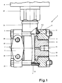
- Fig. 1, 1 is a pressure sensor, which, although the application is not limited to for example a differential pressure sensor should be.
- the differential pressure transducer has two opposite Process connection flanges, both of which are mirror images and are arranged.
- Process connection flanges both of which are mirror images and are arranged.
- the pressure sensor 1 is made of ceramic Measuring cell 2, the measuring cell housing enclosing the measuring cell 2 3, the process connection flanges 4 and 5, the process connection pin 6, 7, and the electronics housing 8 together.
- a detachable screw-nut connection 10, 11 are the process connection flanges 4, 5 so clamped against each other, that they occupy a position in which they the measuring cell housing 3 clamp between them.
- the cylindrical intermediate piece 31 represents the spatial Connection between the measuring cell housing 3 and the electronics housing 8 ago. Inside the intermediate piece 31 are (not shown) the electrical lines arranged, via which the measuring cell 2 with the inside of the electronics housing 8 located electronic circuit in electrical Connection is established.
- a hexagon 81 is molded onto the electronics housing 8. Of the Hexagon 81 is used to initiate a torque with whose help the electronics housing 8 via a not shown Thread with the thread not shown Intermediate piece 31 of the measuring cell housing 3 is screwed.
- the electronics housing 8 encloses in addition to the electrical Circuit also electrical connection elements through which the Pressure sensor in electrical connection with an energy supply and / or information processing center stands.
- the electronics housing 8 can also with an electrical Display device, which is an electrical Displays measured value that determined by the pressure measuring cell Pressure of the measuring medium corresponds.
- the flange-shaped Surface 14 with the threaded holes 15 is for fastening the Measuring sensor 1 determined at the measuring location.
- the Pressure measuring cell 2 with the measuring space, inside which there is Medium is located, and thus with the medium itself in spatial connection.
- This spatial connection is manufactured via a connection line, not shown, which at one end at the one enclosing the measuring room Wall and at the other end to the process connection flange 4 is connected.
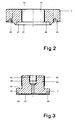
- the bore 61 opens into one short cylindrical cavity 62 (Fig. 3) which serves the pressure of the measuring medium evenly on the circular area of the Distribute measuring membrane 21.
- Internal thread 63 introduced.
- the groove 45 coaxially rotates the bore 41 such that its axis of symmetry with the axis of symmetry of the bore 41 and thus the Process connection flange 4 coincides.
- the bottom of the groove 45 is broken through by another groove 46.
- the housing wall of the measuring cell housing 3 will change Support on the bottom of the groove 45 and is against the in the groove 46 arranged annular seal 12 pressed.
- FIG 3 shows a section through the, from a polymer Plastic, advantageously made of a polyvinylidene fluoride (PVDF) manufactured process connection plug 6.
- the process connection plug 6 consists of a longer section smaller Diameter 64 and a shorter section larger Diameter 65 together.
- the lateral surface of section 64 is provided with an external thread 66.
- the process connection flange 4 is also on the process connection pin 6 due to the different diameters of the sections 64 and 65 an annular shoulder 67 is formed, which extends radially and section 64 is rectangular circulates.
- On the end face facing the measuring cell 2 also runs a groove 68 coaxial to the axis of symmetry Bore 61 and thus that of the process connection pin 6 the cylindrical Cavity 62.
- the process connection pin 6 is so with his External thread 66 in the internal thread 42 of the process connection pin 4 screwed that section 64 the bore 41 penetrates and thereby the shoulder 67 on the Shoulder 44 supports.
- a short piece of the Section 65 of the process connection pin 6 the cylindrical Section 43 of the process connection flange 4.
- the connecting line By connecting the connecting line to the process connection spigot 6, and thus spatial connection of the measuring cell 2 via the bore 61, with the connecting line, the seal the measuring cell 2 opposite the interior of the measuring cell housing 3 by means of the sealing surfaces 69, 21 and the seal 13 is now ensured that the measuring medium, except for the ceramic material of the measuring cell 2 and the polymeric plastic the process connection pin 6, with no other materials can connect.
- the process connection spigot 6 so, from the metallic process connection flange 4 supported and held that even at higher temperatures the tightness of the measuring medium or the process Sealing surfaces is guaranteed.
Landscapes
- Physics & Mathematics (AREA)
- General Physics & Mathematics (AREA)
- Measuring Fluid Pressure (AREA)
Abstract
Claims (3)
- a) Bride métallique (4) de raccordement à un circuit opérationnel pour un capteur mesurant la pression (2, 3) avec présence d'une liaison amovible (10, 11) par laquelle a bride métallique (4) est relié par engagement mécanique au capteur mesurant la pression (2, 3) ; etb) avec présence de moyens de liaison en matière plastique, résistant aux milieux à contrôler et non métalliques, réalisés sous forme de tenons (6) de raccordement à un circuit opérationnel, qui viennent s'appuyer axialement à un épaulement (44) et radialement à une surface enveloppante (47) de la bride (4) ;c) comportant une cavité cylindrique (62) moulée sur le tampon (6) et fermée par une membrane (21) résistante aux milieux à contrôler du capteur mesurant la pression (21);d) par laquelle la cellule sensible (2) du capteur mesurant la pression est en liaison spatiale avec les milieux dont on souhaite mesurer la pression, tandis quee) la cavité cylindrique (62) est étanche par rapport à l'espace intérieur du carter (3) contenant la cellule sensible, et ce carter (3) est étanche par rapport à l'atmosphère extérieure ;f) tandis que la bride (4) s'appuie de manière étanche, par le fond d'une rainure (45) avec inclusion d'un joint (12) en forme de bague, sur une face annulaire du carter (3) de la cellule sensible, et qu'en même temps, le tenon de raccordement (6) s'appuie de manière étanche par une face d'étanchéité (69) avec inclusion d'un autre joint (13) en forme de bague sur une face d'étanchéité de forme annulaire de la membrane (21) de la cellule sensible (2).
- Bride de raccordement à un circuit opérationnel conforme à la revendication 1, avec présence d'un raccord par vis constitué du filetage intérieur (42) de la bride (4) et du filetage extérieur (66) du tampon (6), raccord par lequel ledit tenon (6) est inséré et maintenu à l'intérieur de la bride (4).
- Bourrelet de raccordement à un circuit opérationnel selon la revendication 1, le tenon (6) de raccordement au circuit opérationnel étant fabriqué en un fluorure de polyvinylidène (PVDF).
Applications Claiming Priority (5)
| Application Number | Priority Date | Filing Date | Title |
|---|---|---|---|
| DE19924231823 DE4231823C2 (de) | 1992-09-23 | 1992-09-23 | Prozeßanschlußflansch für Druckmeßaufnehmer |
| DE4231823 | 1992-09-23 | ||
| DE9212768U DE9212768U1 (de) | 1992-09-23 | 1992-09-23 | Prozeßanschlußflansch für Druckmeßaufnehmer |
| DE9212768U | 1992-09-23 | ||
| PCT/DE1993/000870 WO1994007120A1 (fr) | 1992-09-23 | 1993-09-15 | Bride de raccordement a un processus de traitement pour transducteurs de pression |
Publications (2)
| Publication Number | Publication Date |
|---|---|
| EP0613552A1 EP0613552A1 (fr) | 1994-09-07 |
| EP0613552B1 true EP0613552B1 (fr) | 1998-06-03 |
Family
ID=25918773
Family Applications (1)
| Application Number | Title | Priority Date | Filing Date |
|---|---|---|---|
| EP93919006A Expired - Lifetime EP0613552B1 (fr) | 1992-09-23 | 1993-09-15 | Bride de raccordement a un processus de traitement pour transducteurs de pression |
Country Status (8)
| Country | Link |
|---|---|
| US (1) | US5499539A (fr) |
| EP (1) | EP0613552B1 (fr) |
| JP (1) | JP2962831B2 (fr) |
| CA (1) | CA2123581C (fr) |
| DE (1) | DE59308646D1 (fr) |
| DK (1) | DK0613552T3 (fr) |
| ES (1) | ES2116465T3 (fr) |
| WO (1) | WO1994007120A1 (fr) |
Families Citing this family (4)
| Publication number | Priority date | Publication date | Assignee | Title |
|---|---|---|---|---|
| DK0723143T3 (da) * | 1995-01-12 | 1999-03-01 | Endress Hauser Gmbh Co | Indretning til måling af tryk eller differenstryk |
| US8119191B2 (en) | 2003-01-16 | 2012-02-21 | Parker-Hannifin Corporation | Dispensable cured resin |
| DE102010063114A1 (de) * | 2010-12-15 | 2012-06-21 | Endress + Hauser Gmbh + Co. Kg | Flansch für Druckmesszellen oder Druckmittler-Vorrichtungen und Verfahren zur Herstellung solcher Flansche |
| DE102012108611B4 (de) * | 2012-09-14 | 2022-06-15 | Vega Grieshaber Kg | Messwertaufnehmer |
Family Cites Families (6)
| Publication number | Priority date | Publication date | Assignee | Title |
|---|---|---|---|---|
| DE204767C (fr) * | ||||
| US3618390A (en) * | 1969-10-27 | 1971-11-09 | Rosemount Eng Co Ltd | Differential pressure transducer |
| EP0053169A4 (fr) * | 1980-06-12 | 1983-10-04 | Rosemount Inc | Dispositif d'isolation de la bride d'un capteur de pression. |
| US4993265A (en) * | 1988-03-03 | 1991-02-19 | The Foxboro Company | Protected pressure sensor and method of making |
| US5063784A (en) * | 1988-06-06 | 1991-11-12 | Ridenour Ralph Gaylord | Refrigerant transducer assembly and method |
| US5313839A (en) * | 1992-08-31 | 1994-05-24 | Ridenour Ralph Gaylord | Transducer assembly and method |
-
1993
- 1993-09-15 EP EP93919006A patent/EP0613552B1/fr not_active Expired - Lifetime
- 1993-09-15 DK DK93919006T patent/DK0613552T3/da active
- 1993-09-15 DE DE59308646T patent/DE59308646D1/de not_active Expired - Fee Related
- 1993-09-15 JP JP6507686A patent/JP2962831B2/ja not_active Expired - Fee Related
- 1993-09-15 ES ES93919006T patent/ES2116465T3/es not_active Expired - Lifetime
- 1993-09-15 WO PCT/DE1993/000870 patent/WO1994007120A1/fr not_active Ceased
- 1993-09-15 US US08/244,176 patent/US5499539A/en not_active Expired - Fee Related
- 1993-09-15 CA CA002123581A patent/CA2123581C/fr not_active Expired - Fee Related
Also Published As
| Publication number | Publication date |
|---|---|
| JPH06511089A (ja) | 1994-12-08 |
| JP2962831B2 (ja) | 1999-10-12 |
| ES2116465T3 (es) | 1998-07-16 |
| DK0613552T3 (da) | 1999-03-22 |
| US5499539A (en) | 1996-03-19 |
| DE59308646D1 (de) | 1998-07-09 |
| EP0613552A1 (fr) | 1994-09-07 |
| CA2123581A1 (fr) | 1993-09-15 |
| CA2123581C (fr) | 1999-12-07 |
| WO1994007120A1 (fr) | 1994-03-31 |
Similar Documents
| Publication | Publication Date | Title |
|---|---|---|
| EP0594808B1 (fr) | Dispositif permettant de mesurer la pression et la pression differentielle avec une boite filetee en trois parties et une corniere annulaire | |
| EP0723143B1 (fr) | Capteur de pression céramique avec une pièce de connection pour un récipient et une garniture double | |
| EP0759547A1 (fr) | Capteur de pression | |
| EP3308123B1 (fr) | Dispositif de mesure de la pression d'un fluide circulant à travers une conduite | |
| EP2048480A2 (fr) | Capteur de mesure du type de vibration | |
| DE102007004828B4 (de) | Kompaktes, modular aufgebautes magnetisch induktives Durchflussmessgerät und Verfahren zur Herstellung eines solchen Durchflussmessgerätes | |
| DE602005004052T2 (de) | Dichtungsanordnung | |
| DE102004048765A1 (de) | Verbund-System, Verfahren zu dessen Herstellung sowie Messaufnehmer mit einem solchen Verbund-System | |
| EP0613552B1 (fr) | Bride de raccordement a un processus de traitement pour transducteurs de pression | |
| EP0402460B1 (fr) | Debitmetre electromagnetique | |
| DE202019104296U1 (de) | Messsystem | |
| DE102015121425A1 (de) | Vorrichtung zur nicht intrusiven Messung des Drucks eines Fluids | |
| DE102010043781A1 (de) | Messgerät | |
| DE19747273B4 (de) | Sensor zum Messen der elektrischen Leitfähigkeit | |
| EP3309528B1 (fr) | Transmetteur de pression de tubulure | |
| EP1805494A1 (fr) | Capteur de pression a transmission hydraulique de la pression | |
| DE4309380C2 (de) | Verfahren zur Überwachung eines Systems | |
| DE4231823C2 (de) | Prozeßanschlußflansch für Druckmeßaufnehmer | |
| WO2007030960A1 (fr) | Robinet a boisseau spherique | |
| DE102009043503B4 (de) | Medienverteilerrohr für eine Chlorelektrolyse-Anlage | |
| DE9212768U1 (de) | Prozeßanschlußflansch für Druckmeßaufnehmer | |
| EP1484590A2 (fr) | Arrangement pour assurer l'étanchéité d'un élément de mesure | |
| DE102011017266B4 (de) | Rohrförmiger Druckmittler | |
| DE102018131057A1 (de) | Differenzdruck-Messaufnehmer | |
| DE102022105199A1 (de) | Sensor sowie damit gebildetes Meßsystem |
Legal Events
| Date | Code | Title | Description |
|---|---|---|---|
| PUAI | Public reference made under article 153(3) epc to a published international application that has entered the european phase |
Free format text: ORIGINAL CODE: 0009012 |
|
| 17P | Request for examination filed |
Effective date: 19940415 |
|
| AK | Designated contracting states |
Kind code of ref document: A1 Designated state(s): CH DE DK ES FR GB IT LI NL SE |
|
| 17Q | First examination report despatched |
Effective date: 19960103 |
|
| GRAG | Despatch of communication of intention to grant |
Free format text: ORIGINAL CODE: EPIDOS AGRA |
|
| GRAG | Despatch of communication of intention to grant |
Free format text: ORIGINAL CODE: EPIDOS AGRA |
|
| GRAH | Despatch of communication of intention to grant a patent |
Free format text: ORIGINAL CODE: EPIDOS IGRA |
|
| GRAH | Despatch of communication of intention to grant a patent |
Free format text: ORIGINAL CODE: EPIDOS IGRA |
|
| GRAA | (expected) grant |
Free format text: ORIGINAL CODE: 0009210 |
|
| ITF | It: translation for a ep patent filed | ||
| AK | Designated contracting states |
Kind code of ref document: B1 Designated state(s): CH DE DK ES FR GB IT LI NL SE |
|
| REG | Reference to a national code |
Ref country code: CH Ref legal event code: EP |
|
| REF | Corresponds to: |
Ref document number: 59308646 Country of ref document: DE Date of ref document: 19980709 |
|
| REG | Reference to a national code |
Ref country code: CH Ref legal event code: NV Representative=s name: ENDRESS + HAUSER FLOWTEC AG |
|
| REG | Reference to a national code |
Ref country code: ES Ref legal event code: FG2A Ref document number: 2116465 Country of ref document: ES Kind code of ref document: T3 |
|
| GBT | Gb: translation of ep patent filed (gb section 77(6)(a)/1977) |
Effective date: 19980901 |
|
| ET | Fr: translation filed | ||
| PLBQ | Unpublished change to opponent data |
Free format text: ORIGINAL CODE: EPIDOS OPPO |
|
| PLBI | Opposition filed |
Free format text: ORIGINAL CODE: 0009260 |
|
| REG | Reference to a national code |
Ref country code: DK Ref legal event code: T3 |
|
| PLBF | Reply of patent proprietor to notice(s) of opposition |
Free format text: ORIGINAL CODE: EPIDOS OBSO |
|
| 26 | Opposition filed |
Opponent name: ROSEMOUNT INC. Effective date: 19990302 |
|
| NLR1 | Nl: opposition has been filed with the epo |
Opponent name: ROSEMOUNT INC. |
|
| PLBF | Reply of patent proprietor to notice(s) of opposition |
Free format text: ORIGINAL CODE: EPIDOS OBSO |
|
| PGFP | Annual fee paid to national office [announced via postgrant information from national office to epo] |
Ref country code: CH Payment date: 20000816 Year of fee payment: 8 |
|
| PGFP | Annual fee paid to national office [announced via postgrant information from national office to epo] |
Ref country code: SE Payment date: 20000825 Year of fee payment: 8 Ref country code: DK Payment date: 20000825 Year of fee payment: 8 |
|
| PGFP | Annual fee paid to national office [announced via postgrant information from national office to epo] |
Ref country code: ES Payment date: 20000922 Year of fee payment: 8 |
|
| PLBF | Reply of patent proprietor to notice(s) of opposition |
Free format text: ORIGINAL CODE: EPIDOS OBSO |
|
| PG25 | Lapsed in a contracting state [announced via postgrant information from national office to epo] |
Ref country code: DK Free format text: LAPSE BECAUSE OF NON-PAYMENT OF DUE FEES Effective date: 20010915 |
|
| PG25 | Lapsed in a contracting state [announced via postgrant information from national office to epo] |
Ref country code: SE Free format text: LAPSE BECAUSE OF NON-PAYMENT OF DUE FEES Effective date: 20010916 Ref country code: ES Free format text: LAPSE BECAUSE OF NON-PAYMENT OF DUE FEES Effective date: 20010916 |
|
| PG25 | Lapsed in a contracting state [announced via postgrant information from national office to epo] |
Ref country code: LI Free format text: LAPSE BECAUSE OF NON-PAYMENT OF DUE FEES Effective date: 20010930 Ref country code: CH Free format text: LAPSE BECAUSE OF NON-PAYMENT OF DUE FEES Effective date: 20010930 |
|
| REG | Reference to a national code |
Ref country code: GB Ref legal event code: IF02 |
|
| EUG | Se: european patent has lapsed |
Ref document number: 93919006.2 |
|
| REG | Reference to a national code |
Ref country code: CH Ref legal event code: PL |
|
| REG | Reference to a national code |
Ref country code: DK Ref legal event code: EBP |
|
| PLBO | Opposition rejected |
Free format text: ORIGINAL CODE: EPIDOS REJO |
|
| PLBN | Opposition rejected |
Free format text: ORIGINAL CODE: 0009273 |
|
| STAA | Information on the status of an ep patent application or granted ep patent |
Free format text: STATUS: OPPOSITION REJECTED |
|
| 27O | Opposition rejected |
Effective date: 20021012 |
|
| NLR2 | Nl: decision of opposition |
Effective date: 20021012 |
|
| REG | Reference to a national code |
Ref country code: ES Ref legal event code: FD2A Effective date: 20021011 |
|
| PGFP | Annual fee paid to national office [announced via postgrant information from national office to epo] |
Ref country code: FR Payment date: 20050823 Year of fee payment: 13 |
|
| PGFP | Annual fee paid to national office [announced via postgrant information from national office to epo] |
Ref country code: GB Payment date: 20050905 Year of fee payment: 13 |
|
| PGFP | Annual fee paid to national office [announced via postgrant information from national office to epo] |
Ref country code: DE Payment date: 20050912 Year of fee payment: 13 |
|
| PGFP | Annual fee paid to national office [announced via postgrant information from national office to epo] |
Ref country code: NL Payment date: 20050914 Year of fee payment: 13 |
|
| PGFP | Annual fee paid to national office [announced via postgrant information from national office to epo] |
Ref country code: IT Payment date: 20060930 Year of fee payment: 14 |
|
| PG25 | Lapsed in a contracting state [announced via postgrant information from national office to epo] |
Ref country code: NL Free format text: LAPSE BECAUSE OF NON-PAYMENT OF DUE FEES Effective date: 20070401 |
|
| PG25 | Lapsed in a contracting state [announced via postgrant information from national office to epo] |
Ref country code: DE Free format text: LAPSE BECAUSE OF NON-PAYMENT OF DUE FEES Effective date: 20070403 |
|
| GBPC | Gb: european patent ceased through non-payment of renewal fee |
Effective date: 20060915 |
|
| NLV4 | Nl: lapsed or anulled due to non-payment of the annual fee |
Effective date: 20070401 |
|
| REG | Reference to a national code |
Ref country code: FR Ref legal event code: ST Effective date: 20070531 |
|
| PG25 | Lapsed in a contracting state [announced via postgrant information from national office to epo] |
Ref country code: GB Free format text: LAPSE BECAUSE OF NON-PAYMENT OF DUE FEES Effective date: 20060915 |
|
| PG25 | Lapsed in a contracting state [announced via postgrant information from national office to epo] |
Ref country code: FR Free format text: LAPSE BECAUSE OF NON-PAYMENT OF DUE FEES Effective date: 20061002 |
|
| PG25 | Lapsed in a contracting state [announced via postgrant information from national office to epo] |
Ref country code: IT Free format text: LAPSE BECAUSE OF NON-PAYMENT OF DUE FEES Effective date: 20070915 |