EP0613552B1 - Process connecting flange for pressure transducers - Google Patents
Process connecting flange for pressure transducers Download PDFInfo
- Publication number
- EP0613552B1 EP0613552B1 EP93919006A EP93919006A EP0613552B1 EP 0613552 B1 EP0613552 B1 EP 0613552B1 EP 93919006 A EP93919006 A EP 93919006A EP 93919006 A EP93919006 A EP 93919006A EP 0613552 B1 EP0613552 B1 EP 0613552B1
- Authority
- EP
- European Patent Office
- Prior art keywords
- process connection
- measuring
- metallic
- media
- flange
- Prior art date
- Legal status (The legal status is an assumption and is not a legal conclusion. Google has not performed a legal analysis and makes no representation as to the accuracy of the status listed.)
- Expired - Lifetime
Links
- 238000000034 method Methods 0.000 title claims abstract description 76
- 229920003023 plastic Polymers 0.000 claims abstract description 12
- 239000004033 plastic Substances 0.000 claims abstract description 12
- 238000007789 sealing Methods 0.000 claims description 8
- 239000002033 PVDF binder Substances 0.000 claims description 4
- 229920002981 polyvinylidene fluoride Polymers 0.000 claims description 4
- 239000011796 hollow space material Substances 0.000 claims 2
- 230000000284 resting effect Effects 0.000 claims 2
- 238000005259 measurement Methods 0.000 abstract description 7
- 230000001419 dependent effect Effects 0.000 abstract 1
- 239000000463 material Substances 0.000 description 9
- 239000012528 membrane Substances 0.000 description 9
- 239000000919 ceramic Substances 0.000 description 5
- 229910000831 Steel Inorganic materials 0.000 description 3
- 239000007769 metal material Substances 0.000 description 3
- 239000010959 steel Substances 0.000 description 3
- 239000002253 acid Substances 0.000 description 2
- 230000010365 information processing Effects 0.000 description 2
- 238000004519 manufacturing process Methods 0.000 description 2
- 229910052574 oxide ceramic Inorganic materials 0.000 description 2
- 239000011224 oxide ceramic Substances 0.000 description 2
- 229920000642 polymer Polymers 0.000 description 2
- 239000000126 substance Substances 0.000 description 2
- 229910000640 Fe alloy Inorganic materials 0.000 description 1
- 241000530268 Lycaena heteronea Species 0.000 description 1
- GRYLNZFGIOXLOG-UHFFFAOYSA-N Nitric acid Chemical class O[N+]([O-])=O GRYLNZFGIOXLOG-UHFFFAOYSA-N 0.000 description 1
- FAPWRFPIFSIZLT-UHFFFAOYSA-M Sodium chloride Chemical class [Na+].[Cl-] FAPWRFPIFSIZLT-UHFFFAOYSA-M 0.000 description 1
- 150000007513 acids Chemical class 0.000 description 1
- 229910045601 alloy Inorganic materials 0.000 description 1
- 239000000956 alloy Substances 0.000 description 1
- 238000009530 blood pressure measurement Methods 0.000 description 1
- 229910010293 ceramic material Inorganic materials 0.000 description 1
- 229910052804 chromium Inorganic materials 0.000 description 1
- 238000005260 corrosion Methods 0.000 description 1
- 230000007797 corrosion Effects 0.000 description 1
- 230000007423 decrease Effects 0.000 description 1
- 239000012530 fluid Substances 0.000 description 1
- 239000007789 gas Substances 0.000 description 1
- 238000010438 heat treatment Methods 0.000 description 1
- JEIPFZHSYJVQDO-UHFFFAOYSA-N iron(III) oxide Inorganic materials O=[Fe]O[Fe]=O JEIPFZHSYJVQDO-UHFFFAOYSA-N 0.000 description 1
- 239000007788 liquid Substances 0.000 description 1
- 239000000203 mixture Substances 0.000 description 1
- 229910052750 molybdenum Inorganic materials 0.000 description 1
- 229910052759 nickel Inorganic materials 0.000 description 1
- 235000002639 sodium chloride Nutrition 0.000 description 1
- QAOWNCQODCNURD-UHFFFAOYSA-N sulfuric acid group Chemical class S(O)(O)(=O)=O QAOWNCQODCNURD-UHFFFAOYSA-N 0.000 description 1
- 238000010792 warming Methods 0.000 description 1
Images

Classifications
-
- G—PHYSICS
- G01—MEASURING; TESTING
- G01L—MEASURING FORCE, STRESS, TORQUE, WORK, MECHANICAL POWER, MECHANICAL EFFICIENCY, OR FLUID PRESSURE
- G01L19/00—Details of, or accessories for, apparatus for measuring steady or quasi-steady pressure of a fluent medium insofar as such details or accessories are not special to particular types of pressure gauges
- G01L19/06—Means for preventing overload or deleterious influence of the measured medium on the measuring device or vice versa
- G01L19/0627—Protection against aggressive medium in general
-
- G—PHYSICS
- G01—MEASURING; TESTING
- G01L—MEASURING FORCE, STRESS, TORQUE, WORK, MECHANICAL POWER, MECHANICAL EFFICIENCY, OR FLUID PRESSURE
- G01L19/00—Details of, or accessories for, apparatus for measuring steady or quasi-steady pressure of a fluent medium insofar as such details or accessories are not special to particular types of pressure gauges
- G01L19/0007—Fluidic connecting means
Definitions
- the invention relates to a process connection flange for pressure transducers with a detachable connection, with which the process connection flange with the pressure sensor is positively connected and with connection means which of the pressure transducers with the measuring medium, its pressure is to be measured, is spatially connected.
- Such transducers consist of the actual ceramic measuring cell, which is arranged in the interior of the measuring cell housing, the ring-shaped measuring cell housing, and the two uniform process connection flanges arranged in mirror image to one another, which clamp the measuring cell with the measuring cell housing by means of detachable screw connections in a positive and sealing manner between them .
- the measuring cell is connected to an electronic circuit via electrical connecting lines.
- the electronic circuit is enclosed in a housing.
- the electronics housing also has connection means for electrically connecting the measurement sensor to an energy supply and / or information processing center.
- the electronics housing can also be equipped with a display device for direct display of the pressure.
- the measurement task of the sensor is very common in the pressure measurement of aggressive or corrosive Media, both gaseous and fluid.
- the process connection flanges to manufacture from a material which resistant to the aggressiveness or corrosiveness of the measuring media is.
- the ring-shaped seals which between the ceramic measuring cell and the process connection flanges or between the measuring cell housing and the process connection flanges clamped, must consist of a material, which is also resistant to the measuring media.
- Process connection flanges made of high-alloy, rustproof Steels, e.g. B. X 6 CrNiMoTi 17122 1.4571 or highly corrosion-resistant Ni, Co, Cr, Mo, Fe alloys are special suitable for this.
- WO 81/03678 describes a process connection flange for one Pressure sensor with a measuring membrane metallic measuring cell described. with a detachable Connection through which a metallic Process connection flange form-fitting with the Pressure sensor is connected. with a non-metallic process spigot that the Process connection flange penetrates, and the axially one shoulder and supported radially on a lateral surface.
- the process connection spigot has connection means. about which the pressure sensor with the measuring media, its pressure is to be measured, is spatially connected. By the connection means do not stand the introduced measuring media only with the metallic membrane, but also beyond with a surface of a measuring body, the one in front of the Membrane arranged in the measuring cell is limited in Connection.
- a capacitive high-pressure meter is known from US Pat. No. 4,617,607 known.
- This sensor has an oxide ceramic measuring cell and a metallic case as well as a metallic one Connection element made of a weldable non-media-resistant steel.
- On the connection element is a circular cylindrical opposite the measuring membrane Formed opening, which has a hole with the Measuring media is connected.
- the disadvantage of this item lies in that various metallic parts directly the Aggressiveness of the aggressive measuring media are exposed.
- the invention has the task of a To propose a process connection flange which ensures that in addition to the media-resistant material of Pressure measuring cell only parts from one of the aggressive and / or corrosive measuring media resistant plastic can connect to these media and defy it the high temperatures that occur, one that Pressure tightness of the pressure sensor guaranteed Dimensional stability of the plastic parts at the same time Closing the interior of the measuring cell housing compared to the measuring media and the measuring cell housing is given to the environment.
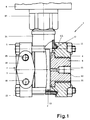
- Fig. 1, 1 is a pressure sensor, which, although the application is not limited to for example a differential pressure sensor should be.
- the differential pressure transducer has two opposite Process connection flanges, both of which are mirror images and are arranged.
- Process connection flanges both of which are mirror images and are arranged.
- the pressure sensor 1 is made of ceramic Measuring cell 2, the measuring cell housing enclosing the measuring cell 2 3, the process connection flanges 4 and 5, the process connection pin 6, 7, and the electronics housing 8 together.
- a detachable screw-nut connection 10, 11 are the process connection flanges 4, 5 so clamped against each other, that they occupy a position in which they the measuring cell housing 3 clamp between them.
- the cylindrical intermediate piece 31 represents the spatial Connection between the measuring cell housing 3 and the electronics housing 8 ago. Inside the intermediate piece 31 are (not shown) the electrical lines arranged, via which the measuring cell 2 with the inside of the electronics housing 8 located electronic circuit in electrical Connection is established.
- a hexagon 81 is molded onto the electronics housing 8. Of the Hexagon 81 is used to initiate a torque with whose help the electronics housing 8 via a not shown Thread with the thread not shown Intermediate piece 31 of the measuring cell housing 3 is screwed.
- the electronics housing 8 encloses in addition to the electrical Circuit also electrical connection elements through which the Pressure sensor in electrical connection with an energy supply and / or information processing center stands.
- the electronics housing 8 can also with an electrical Display device, which is an electrical Displays measured value that determined by the pressure measuring cell Pressure of the measuring medium corresponds.
- the flange-shaped Surface 14 with the threaded holes 15 is for fastening the Measuring sensor 1 determined at the measuring location.
- the Pressure measuring cell 2 with the measuring space, inside which there is Medium is located, and thus with the medium itself in spatial connection.
- This spatial connection is manufactured via a connection line, not shown, which at one end at the one enclosing the measuring room Wall and at the other end to the process connection flange 4 is connected.
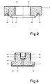
- the bore 61 opens into one short cylindrical cavity 62 (Fig. 3) which serves the pressure of the measuring medium evenly on the circular area of the Distribute measuring membrane 21.
- Internal thread 63 introduced.
- the groove 45 coaxially rotates the bore 41 such that its axis of symmetry with the axis of symmetry of the bore 41 and thus the Process connection flange 4 coincides.
- the bottom of the groove 45 is broken through by another groove 46.
- the housing wall of the measuring cell housing 3 will change Support on the bottom of the groove 45 and is against the in the groove 46 arranged annular seal 12 pressed.
- FIG 3 shows a section through the, from a polymer Plastic, advantageously made of a polyvinylidene fluoride (PVDF) manufactured process connection plug 6.
- the process connection plug 6 consists of a longer section smaller Diameter 64 and a shorter section larger Diameter 65 together.
- the lateral surface of section 64 is provided with an external thread 66.
- the process connection flange 4 is also on the process connection pin 6 due to the different diameters of the sections 64 and 65 an annular shoulder 67 is formed, which extends radially and section 64 is rectangular circulates.
- On the end face facing the measuring cell 2 also runs a groove 68 coaxial to the axis of symmetry Bore 61 and thus that of the process connection pin 6 the cylindrical Cavity 62.
- the process connection pin 6 is so with his External thread 66 in the internal thread 42 of the process connection pin 4 screwed that section 64 the bore 41 penetrates and thereby the shoulder 67 on the Shoulder 44 supports.
- a short piece of the Section 65 of the process connection pin 6 the cylindrical Section 43 of the process connection flange 4.
- the connecting line By connecting the connecting line to the process connection spigot 6, and thus spatial connection of the measuring cell 2 via the bore 61, with the connecting line, the seal the measuring cell 2 opposite the interior of the measuring cell housing 3 by means of the sealing surfaces 69, 21 and the seal 13 is now ensured that the measuring medium, except for the ceramic material of the measuring cell 2 and the polymeric plastic the process connection pin 6, with no other materials can connect.
- the process connection spigot 6 so, from the metallic process connection flange 4 supported and held that even at higher temperatures the tightness of the measuring medium or the process Sealing surfaces is guaranteed.
Landscapes
- Physics & Mathematics (AREA)
- General Physics & Mathematics (AREA)
- Measuring Fluid Pressure (AREA)
Abstract
Description
Die Erfindung bezieht sich auf einen Prozeßanschlußflansch für Druckmeßaufnehmer mit einer lösbaren Verbindung, mit welcher der Prozeßanschlußflansch mit dem Druckmeßaufnehmer formschlüssig verbunden ist und mit Anschlußmitteln über welche der Druckmeßaufnehmer mit dem Meßmedium, dessen Druck gemessen werden soll, in räumlicher Verbindung steht.The invention relates to a process connection flange for pressure transducers with a detachable connection, with which the process connection flange with the pressure sensor is positively connected and with connection means which of the pressure transducers with the measuring medium, its pressure is to be measured, is spatially connected.
Solche in räumlicher und formschlüssiger Verbindung mit dem Prozeßanschlußflansch stehende Druckmeßaufnehmer dienen dazu, den Differenz-, Über- und Unterdruck; Durchfluß von Gasen, Dämpfen und Flüssigkeiten; sowie hydrostatisch den Füllstand eines Behälters zu messen.Such in spatial and positive connection with the pressure transducer used for the process connection flange to the differential, positive and negative pressure; Flow of Gases, vapors and liquids; as well as hydrostatically Measure the level of a container.
Nach dem allgemein bekannten Stand der Technik, wie er
z. B. in dem Prospekt
"Meßumformer für Differenzdruck, Deltabar PMD 130",
Januar 1991, insbesondere Seite 6, Zeichnung "Aufbau
des Meßumformers"
der Anmelderin dargestellt ist, bestehen solche Meßumformer
aus der eigentlichen keramischen Meßzelle, welche im Innenraum
des Meßzellengehäuses angeordnet ist, dem ringförmigen
Meßzellengehäuse, sowie den zwei gleichförmigen spiegelbildlich
zueinander angeordneten Prozeßanschlußflanschen, welche
die Meßzelle mit dem Meßzellengehäuse mittels lösbarer
Schraubverbindungen formschlüssig und abdichtend zwischen
sich einspannen. Die Meßzelle steht über elektrische Verbindungsleitungen
mit einer elektronischen Schaltung in Verbindung.
Die elektronische Schaltung ist von einem Gehäuse umschlossen.
Das Elektronikgehäuse weist außerdem Anschlußmittel
zum elektrischen Verbinden des Meßwertaufnehmers mit
einer Energieversorgungs- und/oder Informationsverarbeitungszentrale
auf. Das Elektronikgehäuse kann aber auch mit einem
Anzeigegerät zur direkten Anzeige des Druckes ausgestattet
sein.According to the generally known state of the art, as z. B. in the prospectus
"Transmitter for differential pressure, Deltabar PMD 130", January 1991, especially
As shown by the applicant, such transducers consist of the actual ceramic measuring cell, which is arranged in the interior of the measuring cell housing, the ring-shaped measuring cell housing, and the two uniform process connection flanges arranged in mirror image to one another, which clamp the measuring cell with the measuring cell housing by means of detachable screw connections in a positive and sealing manner between them . The measuring cell is connected to an electronic circuit via electrical connecting lines. The electronic circuit is enclosed in a housing. The electronics housing also has connection means for electrically connecting the measurement sensor to an energy supply and / or information processing center. The electronics housing can also be equipped with a display device for direct display of the pressure.
Um nun die Meßzelle mit dem Meßmedium in räumliche Verbindung zu bringen, durchdringen Bohrungen die beiden prozeßanschlußflansche. An die Bohrungen sind jene Leitungen anschließbar, über die der Meßraum und damit das Meßmedium mit dem Druckmeßaufnehmer in räumlicher Verbindung steht.In order now the measuring cell with the measuring medium in spatial To connect, holes penetrate the two process connection flanges. Those lines are at the holes connectable via which the measuring space and thus the measuring medium is in spatial connection with the pressure sensor.
Sehr häufig besteht die Meßaufgabe des Meßwertaufnehmers
in der Druckmessung von aggressiven oder korrosiven
Medien, sowohl gasförmiger als auch in fluidischer Form. Für
solche Aufgaben ist es notwendig und üblich, die Prozeßanschlußflansche
aus einem Werkstoff herzustellen, welcher
resistent gegen die Aggressivität oder Korrosivität der Meßmedien
ist. Aber auch die ringförmigen Dichtungen, welche
zwischen keramischer Meßzelle und den Prozeßanschlußflanschen
bzw. zwischen den Meßzellengehäuse und den Prozeßanschlußflanschen
eingespannt sind, müssen aus einem Werkstoff bestehen,
welcher ebenfalls resistent gegenüber den Meßmedien ist.
Prozeßanschlußflansche aus hochlegierten, nicht rostenden
Stählen, z. B. X 6 CrNiMoTi 17122 1.4571 oder hochkorrosionsbeständige
Ni, Co, Cr, Mo, Fe - Legierungen sind besonders
geeignet hierzu.The measurement task of the sensor is very common
in the pressure measurement of aggressive or corrosive
Media, both gaseous and fluid. For
such tasks, it is necessary and usual, the process connection flanges
to manufacture from a material which
resistant to the aggressiveness or corrosiveness of the measuring media
is. But also the ring-shaped seals, which
between the ceramic measuring cell and the process connection flanges
or between the measuring cell housing and the process connection flanges
clamped, must consist of a material,
which is also resistant to the measuring media.
Process connection flanges made of high-alloy, rustproof
Steels,
Bei der Anwendung von Druckmeßgeräten unter besonders schwierigen Bedingungen jedoch z. B. in einer Chemieanlage, besteht die Notwendigkeit, solche Medien messen zu müssen, deren Aggressivität und/oder Korrosivität weit über der Beständigkeit der üblicherweise verwendeten Flanschwerkstoffe liegt. Dies können z. B. Kupfer- oder Natriumchloride, Mischungen von Salz- und Salpetersäuren, oder Schwefelsäuren im erhitzten Zustand sein. Um zu Verhindern, daß der Aggressivität oder Korrosivität nichtbeständige Werkstoff mit dem Meßmedien in Verbindung tritt, wurde bereits vorgeschlagen, Prozeßanschlußflansche statt aus einem metallischen Werkstoff aus einem polymeren Kunststoff, welcher widerstandsfähig gegenüber den meisten Säuren oder Basen ist, herzustellen.When using pressure gauges under particular difficult conditions, however. B. in a chemical plant, there is a need to measure such media their aggressiveness and / or corrosiveness far beyond the durability of the flange materials commonly used lies. This can e.g. B. copper or sodium chlorides, mixtures of hydrochloric and nitric acids, or sulfuric acids in heated condition. To prevent the aggressiveness or corrosiveness of non-stable material with the measuring media has already been suggested Process connection flanges instead of a metallic material made of a polymer plastic, which is resistant compared to most acids or bases.
Die mit dem Prozeßablauf in solchen Chemieanlagen verbundene hohe Erhitzung des Meßmediums bringt aber den Nachteil, daß solche Kunststoffflansche zwar resistent gegenüber den Meßmedien sind, jedoch infolge der hohen Temperatur ihre Stabilität aufgeben, was zu Undichtigkeiten und damit gefährlichem Austreten von Meßmedien an den formschlüssigen Verbindungen zwischen den Prozeßanschlußflanschen und dem Meßzellengehäuse führen kann.The associated with the process flow in such chemical plants high heating of the measuring medium brings the Disadvantage that such plastic flanges are resistant compared to the measuring media, but due to the high Temperature give up its stability, causing leaks and thus dangerous leakage of measuring media to the positive connections between the Lead process connection flanges and the measuring cell housing can.
In der WO 81/03678 ist ein Prozeßanschlußflansch für einen Druckmeßaufnehmer mit einer eine Meßmembran aufweisenden metallischen Meßzelle beschrieben. mit einer lösbaren Verbindung, durch welche ein metallische Prozeßanschlußflansch formschlüssig mit dem Druckmeßaufnehmer verbunden ist. mit einem nichtmetallischen Prozeßanschlußzapfen, der den Prozeßanschlußflansch durchdringt, und der sich axial an einer Schulter und radial an einer Mantelfläche abstützt. Der Prozeßanschlußzapfen weist Anschlußmittel auf. über welche der Druckmeßaufnehmer mit den Meßmedien, dessen Druck gemessen werden soll, in räumlicher Verbindung steht. Durch die Anschlußmittel stehen die eingeleiteten Meßmedien nicht nur mit der metallische Membran, sonder darüber hinaus auch mit einer Oberfläche eines Meßkörpers, der einen vor der Membran in der Meßzelle angeordneten Hohlraum begrenzt in Verbindung. WO 81/03678 describes a process connection flange for one Pressure sensor with a measuring membrane metallic measuring cell described. with a detachable Connection through which a metallic Process connection flange form-fitting with the Pressure sensor is connected. with a non-metallic process spigot that the Process connection flange penetrates, and the axially one shoulder and supported radially on a lateral surface. The process connection spigot has connection means. about which the pressure sensor with the measuring media, its pressure is to be measured, is spatially connected. By the connection means do not stand the introduced measuring media only with the metallic membrane, but also beyond with a surface of a measuring body, the one in front of the Membrane arranged in the measuring cell is limited in Connection.
Aus der US-PS 4,617,607 ist ein kapazitiver Hochdruckmesser bekannt. Dieser Sensor weist eine oxydkeramische Messzelle und ein metallisches Gehäuse sowie ein metallisches Anchlußelement aus einem schweißbaren nichtmeßmedienbeständigen Stahl auf. An dem Anschlußelement ist der Meßmembran gegenüberliegend eine kreiszylindrische Öffnung angeformt, welche über eine Bohrung mit den Meßmedien in Verbindung steht. Eine kreisringförmige Platte aus einem rost- und säurebeständigen Stahl schließt die kreiszylindrische Öffnung gegenüber der oxydkeramischen Membran ab. Die kreiszylindrische Öffnung bewirkt, daß die Membran vollständig gleichmäßig von dem zu messenden Druck beaufschlagt wird. Der Nachteil dieses Gegenstandes liegt darin, daß verschiedene metallische Teile direkt der Aggressivität der aggressiven Meßmedien ausgesetzt sind.A capacitive high-pressure meter is known from US Pat. No. 4,617,607 known. This sensor has an oxide ceramic measuring cell and a metallic case as well as a metallic one Connection element made of a weldable non-media-resistant steel. On the connection element is a circular cylindrical opposite the measuring membrane Formed opening, which has a hole with the Measuring media is connected. An annular plate made of rust and acid resistant steel circular cylindrical opening opposite the oxide ceramic Membrane. The circular cylindrical opening causes the Membrane completely even from the pressure to be measured is applied. The disadvantage of this item lies in that various metallic parts directly the Aggressiveness of the aggressive measuring media are exposed.
Demgegenüber stellt sich die Erfindung die Aufgabe, einen Prozeßanschlußflansch vorzuschlagen, welcher gewährleistet, daß außer dem meßmedienbeständigen Werkstoff der Druckmeßzelle nur Teile aus einem dem aggressiven und/oder korrosiven Meßmedien widerstandsfähigen Kunststoff mit diesen Medien in Verbindung treten kann und dabei, trotzt der auftretenden hohen Temperaturen, eine die Druckdichtheit des Druckmeßaufnehmers gewährleistete Formstabilität der Kunststoffteile bei gleichzeitigem Verschließen des Innenraumes des Meßzellengehäuses gegenüber den Meßmedien und des Meßzellengehäuses gegenüber der Umwelt gegeben ist.In contrast, the invention has the task of a To propose a process connection flange which ensures that in addition to the media-resistant material of Pressure measuring cell only parts from one of the aggressive and / or corrosive measuring media resistant plastic can connect to these media and defy it the high temperatures that occur, one that Pressure tightness of the pressure sensor guaranteed Dimensional stability of the plastic parts at the same time Closing the interior of the measuring cell housing compared to the measuring media and the measuring cell housing is given to the environment.
Gelöst wird diese Aufgabe durch die in dem Patentanspruch 1
gekennzeichneten Merkmale. Weitere Merkmale der Erfindung
sind in den Unteransprüchen gekennzeichnet. This problem is solved by the in
Die Erfindung soll anhand der Zeichnungen weiter beschrieben werden.The invention is further based on the drawings to be discribed.
Es zeigen:
- Fig. 1
- einen Druckmeßaufnehmer, bei welchem der erfindungsgemäße Prozeßanschlußflansch zur Anwendung kommt.
- Fig. 2
- einen Schnitt durch den Prozeßanschlußflansch.
- Fig. 3
- einen Schnitt durch den Prozeßanschlußzapfen.
- Fig. 1
- a pressure sensor in which the process connection flange according to the invention is used.
- Fig. 2
- a section through the process connection flange.
- Fig. 3
- a section through the process connection pin.
In Fig. 1 ist mit 1 ein Druckaufnehmer dargestellt, der, obwohl die Anwendung nicht darauf beschränkt ist, beispielsweise ein Differenzdruckaufnehmer sein soll. Zum messen des Differenzdruckes ist es notwendig, die Druckmeßzelle mit beiden Drücken zu beaufschlagen, deshalb besitzt der Differenzdruckaufnehmer zwei gegenüberliegende Prozeßanschlußflansche, die beide spiegelbildlich aufgebaut und angeordnet sind. Der besseren Erklärung wegen, ist nachfolgend jedoch nur eine Seite des Differenzdruckaufnehmers 1 betrachtet.In Fig. 1, 1 is a pressure sensor, which, although the application is not limited to for example a differential pressure sensor should be. To measure the differential pressure, it is necessary therefore apply pressure to the pressure measuring cell with both pressures the differential pressure transducer has two opposite Process connection flanges, both of which are mirror images and are arranged. For the better explanation, is however, only one side of the differential pressure sensor below 1 considered.
Der Druckmeßaufnehmer 1 setzt sich aus der keramischen
Meßzelle 2, dem die Meßzelle 2 umschließenden Meßzellengehäuse
3, den Prozeßanschlußflanschen 4 und 5, dem Prozeßanschlußzapfen
6, 7, sowie dem Elektronikgehäuse 8 zusammen.
Mittels einer lösbaren Schrauben-Muttern-Verbindung 10, 11
sind die Prozeßanschlußflansche 4, 5 so gegeneinander gespannt,
daß sie eine Lage einnehmen, in welcher sie das Meßzellengehäuse
3 zwischen sich einspannen. Dabei stützen sich
die Prozeßanschlußflansche 4, 5 unter Einschließen von ringförmigen
Dichtungen 12, 13 sowohl an dem Meßzellengehäuse 3
als auch an der keramischen Meßzelle 2 ab. Zur Herstellung
der lösbaren Schrauben-Muttern-Verbindung 10, 11 durchdringen
die Bolzen der Schrauben 10 die Prozeßanschlußflansche 4, 5.The
Das zylindrische Zwischenstück 31 stellt die räumliche
Verbindung zwischen dem Meßzellengehäuse 3 und dem Elektronikgehäuse
8 her. Im Innern des Zwischenstückes 31 sind
(nicht dargestellt) die elektrischen Leitungen angeordnet,
über welche die Meßzelle 2 mit der im Innern des Elektronikgehäuses
8 befindlichen elektronischen Schaltung in elektrischer
Verbindung steht.The cylindrical
Auf der, dem Zwischenstück 31 zugewandten Seite ist an
dem Elektronikgehäuse 8 ein Sechskant 81 angeformt. Der
Sechskant 81 dient der Einleitung eines Drehmomentes, mit
dessen Hilfe das Elektronikgehäuse 8 über ein nicht dargestelltes
Gewinde mit dem nichtdargestellten Gewinde des
Zwischenstückes 31 des Meßzellengehäuses 3 verschraubt ist.
Das Elektronikgehäuse 8 umschließt außer der elektrischen
Schaltung auch elektrische Anschlußelemente, über welche der
Druckmeßaufnehmer in elektrischer Verbindung mit einer Energieversorgungs-
und/oder Informationsverarbeitungszentrale
steht. Das Elektronikgehäuse 8 kann außerdem mit einem elektrischen
Anzeigegerät ausgestattet sein, welches einen elektrischen
Meßwert anzeigt, der dem von der Druckmeßzelle ermittelten
Druck des Meßmediums entspricht. Die flanschförmige
Fläche 14 mit den Gewindebohrungen 15 ist zur Befestigung des
Meßwertaufnehmers 1 am Meßort bestimmt.On the side facing the
Zur Erfassung des Meßwertes ist es notwendig, daß die
Druckmeßzelle 2 mit dem Meßraum, in dessen Inneren sich das
Meßmedium befindet, und damit mit dem Meßmedium selbst in
räumlicher Verbindung steht. Diese räumliche Verbindung ist
über eine nichtdargestellte Verbindungsleitung hergestellt,
welche an ihrem einen Ende an der, den Meßraum umschließenden
Wandung und an dem anderen Ende an dem Prozeßanschlußflansch
4 angeschlossen ist. Zur räumlichen Verbindung der Verbindungsleitung
mit der Meßzelle 2 durchdringt eine Bohrung 61
den Prozeßanschlußflansch 4. Die Bohrung 61 mündet in einem
kurzen zylindrischen Hohlraum 62 (Fig. 3) welcher dazu dient,
den Druck des Meßmediums gleichmäßig auf die Kreisfläche der
Meßmembran 21 zu verteilen. Zum Anschluß der Verbindungsleitung
an dem Prozeßanschlußflansch 4 ist in die Bohrung 61 ein
Innengewinde 63 eingebracht.To record the measured value, it is necessary that the
Um nun den Druck eines aggressiven oder korrosiven
Mediums messen zu können, ist es erforderlich, nur solche
Werkstoffe mit dem Meßmedium in Verbindung zu bringen, welche
widerstandsfähig gegenüber diesen Medien sind. Die keramische
Meßzelle besitzt diese Eigenschaft. Bei Wahl eines geeigneten
Werkstoffes ist dies ebenfalls für die Verbindungsleitung der
Fall. Die metallischen Prozeßanschlußflansche sind jedoch
sehr häufig bei extrem aggressiven und korrosiven Medien
nicht einsetzbar. Es muß deshalb auf einen nichtmetallischen
Werkstoff, z. B. auf einen polymeren Kunststoff zurückgegriffen
werden. Solche Kunststoffe haben aber den Nachteil, daß
ihre Formstabilität mit zunehmender Erwärmung stark abnimmt,
sodaß eine Abdichtung zwischen der Meßzelle 2 und dem Innenraum
des Meßzellengehäuses 3, sowie zwischen dem Meßzellengehäuse
3 und der Umwelt auch durch den Einschluß der ringförmigen
Dichtungen 12 und 13 nicht mehr gewährleistet ist. Zur
Behebung dieser Nachteile ist ein Prozeßanschlußzapfen 6
vorgesehen, welcher den Prozeßanschlußflansch 4 so durchdringt,
daß außer der Meßmembran 21 nur der Prozeßanschlußzapfen
6 mit dem Meßmedium in Verbindung treten kann. Ohne
jedoch auf die, durch einen metallischen Flansch gegebene
temperaturbeständige Stabilität des Prozeßanschlußflansches 4
zu verzichten.To now the pressure of an aggressive or corrosive
To be able to measure the medium, it is only necessary to measure it
To bring materials into contact with the measuring medium, which
are resistant to these media. The ceramic
Measuring cell has this property. When choosing a suitable one
This is also for the connecting line of the material
Case. The metallic process connection flanges are however
very often with extremely aggressive and corrosive media
Not insertable. It must therefore be a non-metallic
Material, e.g. B. resorted to a polymeric plastic
will. However, such plastics have the disadvantage that
their dimensional stability decreases sharply with increasing warming,
so that a seal between the measuring
Wie aus Figur 2 ersichtlich ist, durchdringt eine Bohrung
41 den Prozeßanschlußflansch 4 koaxial zu seiner Symmetrieachse.
Der Prozeßanschlußflansch 4 ist wie bisher aus
einem formstabilen metallischen Werkstoff hergestellt. Die
Mantelfläche der Bohrung 41 ist mit einem Innengewinde 42
versehen. Auf der, der Meßzelle 2 zugewandten Seite mündet
die Bohrung 41 in einem zylindrischen Abschnitt 43 größeren
Durchmessers. Dabei weist der Abschnitt 43 eine Mantelfläche
47 auf. Durch die unterschiedlichen Durchmesser von Bohrung
42 und zylindrischen Abschnitt 43 ist an dem Boden des zylindrischen
Abschnittes 43 eine, sich radial erstreckende
ringförmige Schulter 44 ausgebildet. Weiter ist an der, der
Meßzelle 2 zugewandten Stirnseite des Prozeßanschlußflansches
4 eine Nut 45 von rechteckigem Querschnitt angeformt. Die Nut
45 umläuft koaxial die Bohrung 41 derart, daß ihre Symmetrieachse
mit der Symmetrieachse der Bohrung 41 und damit des
Prozeßanschlußflansches 4 zusammenfällt. Der Boden der Nut 45
ist durch eine weitere Nut 46 durchbrochen. Im zusammengebauten
Zustand wird sich die Gehäusewand des Meßzellengehäuses 3
an dem Boden der Nut 45 abstützen und wird dabei gegen die in
der Nut 46 angeordnete ringförmige Dichtung 12 gepresst.As can be seen from Figure 2, penetrates a
Figur 3 zeigt einen Schnitt durch den, aus einem polymeren
Kunststoff, vorteilhaft aus einem Polyvinylidenfluorid
(PVDF) hergestellten Prozeßanschlußzapfen 6. Der Prozeßanschlußzapfen
6 setzt sich aus einem längeren Abschnitt kleineren
Durchmessers 64 und einen kürzeren Abschnitt größeren
Durchmessers 65 zusammen. Die Mantelfläche des Abschnittes 64
ist mit einem Außengewinde 66 versehen. Wie in der Bohrung 41
des Prozeßanschlußflansches 4 ist auch an dem Prozeßanschlußzapfen
6 durch die unterschiedlichen Durchmesser der Abschnitte
64 und 65 eine ringförmige Schulter 67 ausgebildet,
welche sich radial erstreckt und den Abschnitt 64 rechtwinklig
umläuft. An der, der Meßzelle 2 zugewandten Stirnfläche
umläuft außerdem eine Nut 68 koaxial zur Symmetrieachse der
Bohrung 61 und damit der des Prozeßanschlußzapfen 6 den zylindrischen
Hohlraum 62. Im zusammgengebauten Zustand wird
sich eine ringförmige Fläche außerhalb der Membran 21 der
Druckmeßzelle 2 an der, nicht von dem Hohlraum 62 durchbrochenen,
ringförmigen Dichtfläche 69, des Anschlußzapfens 6
abstützen und dabei gegen die, in der Nut 68 angeordnete
ringförmige Dichtung 13 gepresst.Figure 3 shows a section through the, from a polymer
Plastic, advantageously made of a polyvinylidene fluoride
(PVDF) manufactured
Um nun zu verhindern, daß das aggressive oder korrosive
Medium mit dem metallischen Prozeßanschlußflansch 4 in Berührung
kommen kann, ist der Prozeßanschlußzapfen 6 so mit seinem
Außengewinde 66 in das Innengewinde 42 des Prozeßanschlußzapfens
4 eingeschraubt, daß der Abschnitt 64 die Bohrung
41 durchdringt und sich dabei die Schulter 67 an der
Schulter 44 abstützt. Dabei durchdringt ein kurzes Stück des
Abschnittes 65 des Prozeßanschlußzapfens 6 den zylindrischen
Abschnitt 43 des Prozeßanschlußflansches 4. Somit nimmt die
Schulter 44 alle axialen und die Mantelfläche 47 des Abschnittes
43 alle radialen Kräfte auf, welche durch ein temperaturbedingtes
Verformen des polymeren Werkstoffes von dem
Prozeßanschlußzapfen 6 ausgehen.Now to prevent the aggressive or corrosive
Medium in contact with the metallic
Durch den Anschluß der Verbindungsleitung an dem Prozeßanschlußzapfen
6, und damit räumliche Verbinden der Meßzelle
2 über die Bohrung 61, mit der Verbindungsleitung, die Abdichtung
der Meßzelle 2 gegenüber dem Innenraum des Meßzellengehäuses
3 mittels der Dichtflächen 69, 21 und der Dichtung
13 ist nun gewährleistet, daß das Meßmedium, außer dem
keramischen Werkstoff der Meßzelle 2 und dem polymeren Kunststoff
des Prozeßanschlußzapfens 6, mit keinen anderen Werkstoffen
in Verbindung treten kann. Dabei wird der Prozeßanschlußzapfen
6 so, von dem metallischen Prozeßanschlußflansch
4 gestützt und gehalten, daß auch bei höheren Temperaturen
des Meßmediums oder des Prozesses die Dichtheit der
Dichtflächen gewährleistet ist.By connecting the connecting line to the
Selbstverständlich kann anstelle des Anschlusses der
Verbindungsleitung an dem Prozeßanschlußzapfen 6 über das
Gewinde 62 jede andere geeignete Anschlußform realisiert
sein.Of course, instead of connecting the
Connection line to the
Claims (3)
- a) A metallic process connection flange (4) for a pressure sensor (2, 3) with a separable connection (10, 11) by which the metallic process connection flange (4) is positively connected with the pressure sensor (2, 3), andb) with nonmetallic connecting means of plastic in the form of a male process connection (6) which are resistant to the media to be measured and are supported axially on a shoulder (44) and radially on a circumferential surface (47) of the process connection flange (4);c) with a cylindrical hollow space (62) formed on the male process connection (6) and closed with a measured-media-resistant diaphragm (21) of the pressure sensor,d) via which diaphragm (21) the measuring cell (2) of the pressure sensor is physically connected with the media whose pressure is to be measured,e) the cylindrical hollow space (62) being sealed from the interior space of the measuring-cell housing (3), and the measuring-cell housing (3) being sealed from the environment;f) the process connection flange (4) resting with the bottom of a groove (45) against an annular surface of the measuring-cell housing (3), with a sealing ring interposed therebetween, and the male process connection (6) resting with a sealing surface (69) against an annular sealing surface of the diaphragm (21) of the measuring cell (2), with a further sealing ring (13) interposed therebetween.
- A process connection flange as claimed in claim 1 wherein the internal thread (42) of the process connection flange (4) and the external thread (66) of the male process connection (6) form a screw joint by which the male process connection (6) is fitted and held in the process connection flange (4).
- A process connection flange as claimed in claim 1 wherein the male process connection (6) is made of polyvinylidene fluoride (PVDF).
Applications Claiming Priority (5)
| Application Number | Priority Date | Filing Date | Title |
|---|---|---|---|
| DE19924231823 DE4231823C2 (en) | 1992-09-23 | 1992-09-23 | Process connection flange for pressure transducers |
| DE4231823 | 1992-09-23 | ||
| DE9212768U DE9212768U1 (en) | 1992-09-23 | 1992-09-23 | Process connection flange for pressure sensor |
| DE9212768U | 1992-09-23 | ||
| PCT/DE1993/000870 WO1994007120A1 (en) | 1992-09-23 | 1993-09-15 | Process connecting flange for pressure transducers |
Publications (2)
| Publication Number | Publication Date |
|---|---|
| EP0613552A1 EP0613552A1 (en) | 1994-09-07 |
| EP0613552B1 true EP0613552B1 (en) | 1998-06-03 |
Family
ID=25918773
Family Applications (1)
| Application Number | Title | Priority Date | Filing Date |
|---|---|---|---|
| EP93919006A Expired - Lifetime EP0613552B1 (en) | 1992-09-23 | 1993-09-15 | Process connecting flange for pressure transducers |
Country Status (8)
| Country | Link |
|---|---|
| US (1) | US5499539A (en) |
| EP (1) | EP0613552B1 (en) |
| JP (1) | JP2962831B2 (en) |
| CA (1) | CA2123581C (en) |
| DE (1) | DE59308646D1 (en) |
| DK (1) | DK0613552T3 (en) |
| ES (1) | ES2116465T3 (en) |
| WO (1) | WO1994007120A1 (en) |
Families Citing this family (4)
| Publication number | Priority date | Publication date | Assignee | Title |
|---|---|---|---|---|
| DK0723143T3 (en) * | 1995-01-12 | 1999-03-01 | Endress Hauser Gmbh Co | Apparatus for measuring pressure or differential pressure |
| US8119191B2 (en) | 2003-01-16 | 2012-02-21 | Parker-Hannifin Corporation | Dispensable cured resin |
| DE102010063114A1 (en) * | 2010-12-15 | 2012-06-21 | Endress + Hauser Gmbh + Co. Kg | Flange for pressure cells or diaphragm seal devices and method of making such flanges |
| DE102012108611B4 (en) * | 2012-09-14 | 2022-06-15 | Vega Grieshaber Kg | transducer |
Family Cites Families (6)
| Publication number | Priority date | Publication date | Assignee | Title |
|---|---|---|---|---|
| DE204767C (en) * | ||||
| US3618390A (en) * | 1969-10-27 | 1971-11-09 | Rosemount Eng Co Ltd | Differential pressure transducer |
| EP0053169A4 (en) * | 1980-06-12 | 1983-10-04 | Rosemount Inc | Isolating apparatus for a pressure sensor flange. |
| US4993265A (en) * | 1988-03-03 | 1991-02-19 | The Foxboro Company | Protected pressure sensor and method of making |
| US5063784A (en) * | 1988-06-06 | 1991-11-12 | Ridenour Ralph Gaylord | Refrigerant transducer assembly and method |
| US5313839A (en) * | 1992-08-31 | 1994-05-24 | Ridenour Ralph Gaylord | Transducer assembly and method |
-
1993
- 1993-09-15 EP EP93919006A patent/EP0613552B1/en not_active Expired - Lifetime
- 1993-09-15 DK DK93919006T patent/DK0613552T3/en active
- 1993-09-15 DE DE59308646T patent/DE59308646D1/en not_active Expired - Fee Related
- 1993-09-15 JP JP6507686A patent/JP2962831B2/en not_active Expired - Fee Related
- 1993-09-15 ES ES93919006T patent/ES2116465T3/en not_active Expired - Lifetime
- 1993-09-15 WO PCT/DE1993/000870 patent/WO1994007120A1/en not_active Ceased
- 1993-09-15 US US08/244,176 patent/US5499539A/en not_active Expired - Fee Related
- 1993-09-15 CA CA002123581A patent/CA2123581C/en not_active Expired - Fee Related
Also Published As
| Publication number | Publication date |
|---|---|
| JPH06511089A (en) | 1994-12-08 |
| JP2962831B2 (en) | 1999-10-12 |
| ES2116465T3 (en) | 1998-07-16 |
| DK0613552T3 (en) | 1999-03-22 |
| US5499539A (en) | 1996-03-19 |
| DE59308646D1 (en) | 1998-07-09 |
| EP0613552A1 (en) | 1994-09-07 |
| CA2123581A1 (en) | 1993-09-15 |
| CA2123581C (en) | 1999-12-07 |
| WO1994007120A1 (en) | 1994-03-31 |
Similar Documents
| Publication | Publication Date | Title |
|---|---|---|
| EP0594808B1 (en) | Device for measuring pressure and pressure differentials with a three part threaded housing and an angle ring | |
| EP0723143B1 (en) | Ceramic pressure sensor with container connection element and double seal | |
| EP0759547A1 (en) | Pressure sensor | |
| EP3308123B1 (en) | Device for measuring the pressure of a fluid flowing through a pipeline | |
| EP2048480A2 (en) | Measuring sensor of vibration type | |
| DE102007004828B4 (en) | Compact, modular magnetic flowmeter and method of making such a flowmeter | |
| DE602005004052T2 (en) | sealing arrangement | |
| DE102004048765A1 (en) | Composite system, method for its production and sensors with such a composite system | |
| EP0613552B1 (en) | Process connecting flange for pressure transducers | |
| EP0402460B1 (en) | Electromagnetic flow meter | |
| DE202019104296U1 (en) | measuring system | |
| DE102015121425A1 (en) | Device for non-intrusive measurement of the pressure of a fluid | |
| DE102010043781A1 (en) | gauge | |
| DE19747273B4 (en) | Sensor for measuring the electrical conductivity | |
| EP3309528B1 (en) | Tube diaphragm seal | |
| EP1805494A1 (en) | Pressure gauge with hydraulic pressure transmission | |
| DE4309380C2 (en) | System monitoring method | |
| DE4231823C2 (en) | Process connection flange for pressure transducers | |
| WO2007030960A1 (en) | Ball valve | |
| DE102009043503B4 (en) | Media distribution pipe for a chlorine electrolysis plant | |
| DE9212768U1 (en) | Process connection flange for pressure sensor | |
| EP1484590A2 (en) | Sealing of a sensing element | |
| DE102011017266B4 (en) | Pipe-shaped diaphragm seal | |
| DE102018131057A1 (en) | Differential pressure sensor | |
| DE102022105199A1 (en) | Sensor and measuring system formed therewith |
Legal Events
| Date | Code | Title | Description |
|---|---|---|---|
| PUAI | Public reference made under article 153(3) epc to a published international application that has entered the european phase |
Free format text: ORIGINAL CODE: 0009012 |
|
| 17P | Request for examination filed |
Effective date: 19940415 |
|
| AK | Designated contracting states |
Kind code of ref document: A1 Designated state(s): CH DE DK ES FR GB IT LI NL SE |
|
| 17Q | First examination report despatched |
Effective date: 19960103 |
|
| GRAG | Despatch of communication of intention to grant |
Free format text: ORIGINAL CODE: EPIDOS AGRA |
|
| GRAG | Despatch of communication of intention to grant |
Free format text: ORIGINAL CODE: EPIDOS AGRA |
|
| GRAH | Despatch of communication of intention to grant a patent |
Free format text: ORIGINAL CODE: EPIDOS IGRA |
|
| GRAH | Despatch of communication of intention to grant a patent |
Free format text: ORIGINAL CODE: EPIDOS IGRA |
|
| GRAA | (expected) grant |
Free format text: ORIGINAL CODE: 0009210 |
|
| ITF | It: translation for a ep patent filed | ||
| AK | Designated contracting states |
Kind code of ref document: B1 Designated state(s): CH DE DK ES FR GB IT LI NL SE |
|
| REG | Reference to a national code |
Ref country code: CH Ref legal event code: EP |
|
| REF | Corresponds to: |
Ref document number: 59308646 Country of ref document: DE Date of ref document: 19980709 |
|
| REG | Reference to a national code |
Ref country code: CH Ref legal event code: NV Representative=s name: ENDRESS + HAUSER FLOWTEC AG |
|
| REG | Reference to a national code |
Ref country code: ES Ref legal event code: FG2A Ref document number: 2116465 Country of ref document: ES Kind code of ref document: T3 |
|
| GBT | Gb: translation of ep patent filed (gb section 77(6)(a)/1977) |
Effective date: 19980901 |
|
| ET | Fr: translation filed | ||
| PLBQ | Unpublished change to opponent data |
Free format text: ORIGINAL CODE: EPIDOS OPPO |
|
| PLBI | Opposition filed |
Free format text: ORIGINAL CODE: 0009260 |
|
| REG | Reference to a national code |
Ref country code: DK Ref legal event code: T3 |
|
| PLBF | Reply of patent proprietor to notice(s) of opposition |
Free format text: ORIGINAL CODE: EPIDOS OBSO |
|
| 26 | Opposition filed |
Opponent name: ROSEMOUNT INC. Effective date: 19990302 |
|
| NLR1 | Nl: opposition has been filed with the epo |
Opponent name: ROSEMOUNT INC. |
|
| PLBF | Reply of patent proprietor to notice(s) of opposition |
Free format text: ORIGINAL CODE: EPIDOS OBSO |
|
| PGFP | Annual fee paid to national office [announced via postgrant information from national office to epo] |
Ref country code: CH Payment date: 20000816 Year of fee payment: 8 |
|
| PGFP | Annual fee paid to national office [announced via postgrant information from national office to epo] |
Ref country code: SE Payment date: 20000825 Year of fee payment: 8 Ref country code: DK Payment date: 20000825 Year of fee payment: 8 |
|
| PGFP | Annual fee paid to national office [announced via postgrant information from national office to epo] |
Ref country code: ES Payment date: 20000922 Year of fee payment: 8 |
|
| PLBF | Reply of patent proprietor to notice(s) of opposition |
Free format text: ORIGINAL CODE: EPIDOS OBSO |
|
| PG25 | Lapsed in a contracting state [announced via postgrant information from national office to epo] |
Ref country code: DK Free format text: LAPSE BECAUSE OF NON-PAYMENT OF DUE FEES Effective date: 20010915 |
|
| PG25 | Lapsed in a contracting state [announced via postgrant information from national office to epo] |
Ref country code: SE Free format text: LAPSE BECAUSE OF NON-PAYMENT OF DUE FEES Effective date: 20010916 Ref country code: ES Free format text: LAPSE BECAUSE OF NON-PAYMENT OF DUE FEES Effective date: 20010916 |
|
| PG25 | Lapsed in a contracting state [announced via postgrant information from national office to epo] |
Ref country code: LI Free format text: LAPSE BECAUSE OF NON-PAYMENT OF DUE FEES Effective date: 20010930 Ref country code: CH Free format text: LAPSE BECAUSE OF NON-PAYMENT OF DUE FEES Effective date: 20010930 |
|
| REG | Reference to a national code |
Ref country code: GB Ref legal event code: IF02 |
|
| EUG | Se: european patent has lapsed |
Ref document number: 93919006.2 |
|
| REG | Reference to a national code |
Ref country code: CH Ref legal event code: PL |
|
| REG | Reference to a national code |
Ref country code: DK Ref legal event code: EBP |
|
| PLBO | Opposition rejected |
Free format text: ORIGINAL CODE: EPIDOS REJO |
|
| PLBN | Opposition rejected |
Free format text: ORIGINAL CODE: 0009273 |
|
| STAA | Information on the status of an ep patent application or granted ep patent |
Free format text: STATUS: OPPOSITION REJECTED |
|
| 27O | Opposition rejected |
Effective date: 20021012 |
|
| NLR2 | Nl: decision of opposition |
Effective date: 20021012 |
|
| REG | Reference to a national code |
Ref country code: ES Ref legal event code: FD2A Effective date: 20021011 |
|
| PGFP | Annual fee paid to national office [announced via postgrant information from national office to epo] |
Ref country code: FR Payment date: 20050823 Year of fee payment: 13 |
|
| PGFP | Annual fee paid to national office [announced via postgrant information from national office to epo] |
Ref country code: GB Payment date: 20050905 Year of fee payment: 13 |
|
| PGFP | Annual fee paid to national office [announced via postgrant information from national office to epo] |
Ref country code: DE Payment date: 20050912 Year of fee payment: 13 |
|
| PGFP | Annual fee paid to national office [announced via postgrant information from national office to epo] |
Ref country code: NL Payment date: 20050914 Year of fee payment: 13 |
|
| PGFP | Annual fee paid to national office [announced via postgrant information from national office to epo] |
Ref country code: IT Payment date: 20060930 Year of fee payment: 14 |
|
| PG25 | Lapsed in a contracting state [announced via postgrant information from national office to epo] |
Ref country code: NL Free format text: LAPSE BECAUSE OF NON-PAYMENT OF DUE FEES Effective date: 20070401 |
|
| PG25 | Lapsed in a contracting state [announced via postgrant information from national office to epo] |
Ref country code: DE Free format text: LAPSE BECAUSE OF NON-PAYMENT OF DUE FEES Effective date: 20070403 |
|
| GBPC | Gb: european patent ceased through non-payment of renewal fee |
Effective date: 20060915 |
|
| NLV4 | Nl: lapsed or anulled due to non-payment of the annual fee |
Effective date: 20070401 |
|
| REG | Reference to a national code |
Ref country code: FR Ref legal event code: ST Effective date: 20070531 |
|
| PG25 | Lapsed in a contracting state [announced via postgrant information from national office to epo] |
Ref country code: GB Free format text: LAPSE BECAUSE OF NON-PAYMENT OF DUE FEES Effective date: 20060915 |
|
| PG25 | Lapsed in a contracting state [announced via postgrant information from national office to epo] |
Ref country code: FR Free format text: LAPSE BECAUSE OF NON-PAYMENT OF DUE FEES Effective date: 20061002 |
|
| PG25 | Lapsed in a contracting state [announced via postgrant information from national office to epo] |
Ref country code: IT Free format text: LAPSE BECAUSE OF NON-PAYMENT OF DUE FEES Effective date: 20070915 |