EP0613133A2 - Anordnung mit Abtastvorrichtung und Ladevorrichtung, und Plattenspieler mit solcher Anordnung - Google Patents
Anordnung mit Abtastvorrichtung und Ladevorrichtung, und Plattenspieler mit solcher Anordnung Download PDFInfo
- Publication number
- EP0613133A2 EP0613133A2 EP94200317A EP94200317A EP0613133A2 EP 0613133 A2 EP0613133 A2 EP 0613133A2 EP 94200317 A EP94200317 A EP 94200317A EP 94200317 A EP94200317 A EP 94200317A EP 0613133 A2 EP0613133 A2 EP 0613133A2
- Authority
- EP
- European Patent Office
- Prior art keywords
- frame
- sub
- arrangement
- drawer
- elements
- Prior art date
- Legal status (The legal status is an assumption and is not a legal conclusion. Google has not performed a legal analysis and makes no representation as to the accuracy of the status listed.)
- Withdrawn
Links
Images


Classifications
-
- G—PHYSICS
- G11—INFORMATION STORAGE
- G11B—INFORMATION STORAGE BASED ON RELATIVE MOVEMENT BETWEEN RECORD CARRIER AND TRANSDUCER
- G11B17/00—Guiding record carriers not specifically of filamentary or web form, or of supports therefor
- G11B17/02—Details
- G11B17/04—Feeding or guiding single record carrier to or from transducer unit
- G11B17/05—Feeding or guiding single record carrier to or from transducer unit specially adapted for discs not contained within cartridges
- G11B17/053—Indirect insertion, i.e. with external loading means
- G11B17/056—Indirect insertion, i.e. with external loading means with sliding loading means
-
- G—PHYSICS
- G11—INFORMATION STORAGE
- G11B—INFORMATION STORAGE BASED ON RELATIVE MOVEMENT BETWEEN RECORD CARRIER AND TRANSDUCER
- G11B17/00—Guiding record carriers not specifically of filamentary or web form, or of supports therefor
- G11B17/02—Details
- G11B17/022—Positioning or locking of single discs
- G11B17/028—Positioning or locking of single discs of discs rotating during transducing operation
- G11B17/035—Positioning by moving the loading station
-
- G—PHYSICS
- G11—INFORMATION STORAGE
- G11B—INFORMATION STORAGE BASED ON RELATIVE MOVEMENT BETWEEN RECORD CARRIER AND TRANSDUCER
- G11B33/00—Constructional parts, details or accessories not provided for in the other groups of this subclass
- G11B33/02—Cabinets; Cases; Stands; Disposition of apparatus therein or thereon
- G11B33/08—Insulation or absorption of undesired vibrations or sounds
Definitions
- the invention relates to an arrangement for a disc player, in particular an optical or magneto-optical player, which arrangement comprises a scanning device for inscribing and/or reading an information carrier, which scanning device comprises a turntable, for supporting the information carrier, and a scanning unit with an objective, a frame carrying a loading device for the information carrier, which loading device comprises a drawer which is movable in a first direction and a second direction opposite to said first direction for moving the information carrier towards and away from the scanning device, a sub-frame which is supported by the frame and movable relative to the frame between a first position and a second position and which carries a the scanning device, the sub-frame being adapted to cooperate with the drawer for moving the sub-frame from one position to the other position, there being provided means for guiding the sub-frame from one position to the other position.
- a disc player comprising such an arrangement is known from EP-A 0,397,262 (herewith incorporated by reference).
- the known disc player is intended for playing optical or magneto-optical discs and comprises a housing which accommodates an arrangement of the type defined in the opening paragraph.
- the arrangement has a frame carrying a loading device and sub-frame with a turntable.
- the loading device comprises a drawer which extends through a front opening in the housing and is movable between a slid-out position and a slid-in position.
- the scanning device which is secured to the sub-frame in a resilient and damping manner, comprises a turntable and a scanning unit with an objective.
- a construction for guiding the sub-frame is arranged between the frame and the sub-frame.
- This guide construction has two guide elements which project laterally from the sub-frame and which bear on guide surfaces of the frame. During its movement from one position to the other position the drawer is temporarily in contact with the sub-frame in order to move the scanning device between a rest position and an operating position. The guide elements of the sub-frame then follow inclined portions of the guide surfaces of the frame.
- the construction has been dimensioned in such a manner that during the drawer movement the scanning device cannot come into contact with the drawer and an information carrier lying on the drawer, whereas in the operating position the turntable of the scanning device is disposed in such a plane that it can support an inserted information carrier.
- the arrangement in accordance with the invention is characterized in that the means for guiding the sub-frame, which carries the scanning device, from one position to the other position comprise pivotal elements which are each movably connected at one side to the frame and at another side to the sub-frame.
- the sub-frame, which carries the scanning device is coupled to the frame via the pivotal elements, so that the sub-frame and, consequently, the scanning device perform accurately defined movements during movement of the slide, which precludes undesired movements of the sub-frame.
- the arrangement in accordance with the invention has the advantage that a silent movement of the sub-frame carrying the scanning device is possible during the transfer of an information carrier to and its removal from the turntable.
- An embodiment of the arrangement in accordance with the invention is characterized in that, viewed in the directions of movement of the drawer, at least one of the pivotal elements is situated at each of two opposite sides of the sub-frame.
- an embodiment of the arrangement in accordance with the invention is characterized in that the pivotal elements are arranged in pairs at opposite sides of the frame.
- a practical embodiment of the arrangement in accordance with the invention is characterized in that the pivotal elements are connected to the frame and the sub-frame by means of hinges.
- the hinges may comprise, for example, rotatable or fixed pivots or they may be constructed as integral hinges.
- an embodiment of the arrangement in accordance with the invention is characterized in that pivotal elements which are situated after each other viewed in the directions of movement of the drawer have a different effective length and orientation. This step enables the first and second positions to be adjusted relative to one another in such a manner that only minimal displacements of the sub-frame with the scanning device carried by it are necessary.
- An embodiment of the arrangement in accordance with the invention is characterized in that there are provided additional means for guiding the sub-frame from one position to the other position, which additional means comprise at least one pair of guide elements, of which a first element has a guide slot oriented substantially in the directions of movement of the drawer and a second element comprises a guide pin which is engageable in the guide slot, one of the elements being connected to the frame and the other element being connected to the sub-frame.
- said additional means prevent possible lateral excursions of the sub-frame as a result of possible lost motion in the connections, particularly the hinges, between the pivotal elements on the one hand and the frame and the sub-frame on the other hand. Therefore, this embodiment has the advantage that it prevents the formation of further sources of undesired noise.
- one pair of guide elements being situated near a front side and one pair of guide elements being situated near a rear of the sub-frame viewed in the first direction of movement of the drawer.
- An optimum low-noise construction is obtained if a bounding edge of the guide pin and/or a bounding edge of the guide slot is provided with a damping material.
- An embodiment of the arrangement in accordance with the invention is characterized in that the drawer comprises a first coupling element for cooperation with a second coupling element connected to the sub-frame, the coupling elements cooperating with one another in any intermediate position of the sub-frame situated between the first and the second position, and the coupling elements being firmly coupled to one another in the second position.
- An advantage of this embodiment is that the sub-frame movements are derived unambiguously from the drawer movements.
- an important constructional advantage is that the sub-frame can assume an accurately defined second position without the sub-frame bearing against a stop on the frame. Owing to the coupling between the sub-frame and the drawer the last-mentioned position of the sub-frame merely requires an accurately defined position of the drawer.
- a practical embodiment of the arrangement in accordance with the invention is characterized in that the first coupling element has an opening which is bounded by a coupling wall and the second coupling element is a projection adapted to cooperate with the coupling wall, the projection engaging the opening in the second position of the sub-frame.
- the coupling wall engages with the projection of the sub-frame, which is in its first position.
- the first coupling element is disengaged from the second coupling element in the first position of the sub-frame.
- an embodiment of the arrangement in accordance with the invention is characterized in that the frame comprises a guide member which extends in the directions of movement of the drawer and which engages a guideway in the drawer, the guide member extending substantially over the entire frame viewed in the direction of movement of the drawer.
- the invention further relates to a disc player comprising a housing and an arrangement in accordance with the invention.
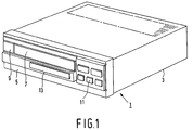
- the optical disc player shown in Fig.1 may be a player intended for optically scanning audio, data and/or video discs, such as CD, CDI, CDROM, CDV and VLP.
- the player bearing the reference numeral 1, comprises a housing 3 having a front side 5 provided with a front opening in which a drawer 7 is arranged.
- actuating keys 9, program keys 11 and a display 13 have been provided at the front side 5.
- the housing accommodates an arrangement in accordance with the invention, which arrangement comprises a loading device with a drawer and a scanning device for optically scanning an optical disc.
- the scanning device may be of a type as disclosed in United States Patent Specification 4,679,185 (PHN 11.356; herewith incorporated by reference), which scanning device comprises an objective arranged on a pivotal arm, or as disclosed in EP-A 0,329,234 (PHN 12.391; herewith incorporated by reference), which scanning device comprises an objective arranged on a slide.
- the arrangement bearing the reference numeral 21 in Figs. 2, 3 and 4 is suitable for use in a disc player of the type shown in Fig. 1.
- the arrangement 21 comprises a frame 23, a sub-frame 25 supported in the frame 23, and a drawer 7.
- the frame 23 can be fixedly mounted in the housing 3 of the disc player 1 shown in Fig. 1.
- a scanning device 37 for optically scanning an optical disc is arranged in the rectangular sub-frame 25 by means of resilient and damping suspension elements 35.
- the scaning device 37 comprises a slide 39 carrying an optical scaning unit 47 and also comprises a turntable 43, which is rotatable about an axis of rotation 43a and has a supporting surface 45 for an optical disc.
- the scanning unit 47 has an objective 48, which is movable along its optical axis 48a.
- the sub-frame is secured to the frame 23 by means of two pairs of pivotal elements 24a, 24b and 24c, 24d.
- the pivotal elements 24a and 24c are each pivotable relative to the frame 23 about an axis 26a and relative to the sub-frame 25 about an axis 26b
- the pivotal elements 24b and 24d are each pivotable relative to the frame 23 about an axis 27a and relative to the sub-frame 25 about an axis 27b.
- the frame 23 comprises trunnions 29a and the sub-frame comprises trunnions 29b for this purpose, the pivotal elements being pivotable about the trunnions which extend through and fit in the pivotal elements to form hinges with these elements.
- the drawer 7 is supported in the frame 23 in a manner known per se and can perform a rectilinear movement as indicated by the arrow P1 in Fig. 2 to transfer an optical disc to the turntable 43. Moreover, the drawer 7 can perform a rectilinear movement as indicated by the arrow P2 to remove an optical disc from the turntable.
- the drawer 7 has a supporting surface 47 for supporting an optical disc.
- the drawer 7 and the sub-frame 25 can be coupled to each other by means of a first coupling element 51, which is secured to the drawer 7, and a second coupling element 53, which is secured to the sub-frame 25 and is formed by a projection.
- the first coupling element has an opening 55 which is bounded by a coupling wall and in which the second coupling element 51 is engageable.
- the first coupling element and/or the second coupling element 53 may be provided with a damping material.
- the drawer 7 In the position illustrated in Figs. 2 and 3 the drawer 7 is in a slid-out position and an optical information carrier can be placed on the supporting surface 47. From the slid-out position the drawer can be moved into a slid-in position illustrated in Fig. 4 in the inward direction as indicated by the arrow P1 by means of an electric motor unit 49. If desired, the disc player may be constructed without the motor unit 49, the drawer then being operated by hand.
- the coupling element 51 of the drawer contacts a stop edge 53a of the coupling element 53 of the sub-frame 25, after which the sub-frame 25 is moved as the inward movement of the drawer 7 proceeds, the pivotal elements 24a to 24d performing pivotal movements which cause the sub-frame to perform both a movement in the direction indicated by the arrow P1 and a movement substantially parallel to the axis of rotation 43a of the turntable 43.
- the last-mentioned movement is performed between the first position of the sub-frame 25 shown in Figs. 2 and 3, hereinafter referred to as the loading position, and the second position shown in Fig. 4, which may also be referred to as the operating position.
- the turntable 43 In the loading position of the sub-frame 25 the turntable 43 is situated in such an area that an information carrier lying on the moving drawer 7 passes the turntable 43 at some distance. After the drawer 7 has come into contact with the sub-frame 25 during the inward movement the scanning device 37 is moved as a result of the movement of the sub-frame 25.
- the mechanism is dimensioned in such a way that at the instant at which the drawer 7 has nearly reached its slid-in position the information carrier lying on the drawer 7 is disposed centrally or at least substantially centrally above the turntable 43.
- the sub-frame 25 In the slid-in position of the drawer 7 the sub-frame 25 is exactly in the operating position, as shown in Fig. 4.
- the turntable 43 has moved so far along its axis of rotation 43a that the information carrier 50, which has been moved inwards by means of the drawer 7, is situated on the supporting surface 45 of the turntable 43 and is disposed at some distance from the drawer 7.
- the projection 53 of the sub-frame engages the opening 55 in the coupling element 51 and the information carrier on the turntable 43 can be scanned.
- a disc-pressure device is employed in order to guarantee that the information carrier remains on the turntable 43 during scanning.
- Figs. 2, 3 and 4 show diagrammatically a suitable disc-pressure device.
- the disc-pressure device bearing the reference numeral 61, comprises a member 63, arranged on the frame 23, with a holder 65 and a pressure means 67.
- the pressure means 67 projects through an opening 69 in the holder 65, and is movable to a limited extent in this opening.
- the pressure means 67 urges the information carrier 50, which is situated on the turntable 43, against the supporting surface 45 of the turntable 43, the desired clamping force in the present example being provided by a magnetic attraction force produced by a first magnetic element arranged in the turntable 43 and a second magnetic pressure element arranged in the pressure means 67.
- the drawer 7 In order to remove an information carrier from the turntable 43 the drawer 7 is moved in the direction indicated by the arrow P2. As a result of the coupling between the drawer 7 and the sub-frame 25 the sub-frame is initially moved until the coupling element formed by the projection 53 has left the opening 55 in the coupling element 51. In this situation the pivotal elements 24a to 24d are again in the position shown in Figs. 2 and 3 and the sub-frame is consequently again in the loading position.
- pivotal elements 24a and 24c used in the arrangement in accordance with the invention have a shorter effective length, measured between the axes 26a and 26b, than that the pivotal elements 24b and 24d, measured between the axes 27a and 27b, and for the same reason they do not extend parallel to the pivotal elements 24b and 24d.
- each pair comprises a first element 71, which is secured to the frame 23 and has a guide slot 71a oriented mainly in the directions P1 and P2, and a second element 73, which is secured to the sub-frame and which comprises a guide pin 73a which fits in the guide slot 71.
- the guide pin 73a extends substantially parallel to the axis of rotation 43a of the turntable 43.
- One pair is situated near a front side 75 and the other pair is situated near a rear side 77 of the sub-frame.
- the edges 71b bounding the pins 73a and/or the slots 71a are provided with a damping or sound-absorbing material, for example a suitable synthetic material, such as a polyurethane.
- the drawer has a guideway 81 which extends in the directions P1, P2 and the frame 23 has a guide member 83 which engages the guideway 81 and which extends over at least the greater part of the depth of the frame 23, viewed in the direction indicated by the arrow P1.
Landscapes
- Feeding And Guiding Record Carriers (AREA)
Priority Applications (1)
| Application Number | Priority Date | Filing Date | Title |
|---|---|---|---|
| EP94200317A EP0613133A3 (de) | 1993-02-16 | 1994-02-09 | Anordnung mit Abtastvorrichtung und Ladevorrichtung, und Plattenspieler mit solcher Anordnung. |
Applications Claiming Priority (3)
| Application Number | Priority Date | Filing Date | Title |
|---|---|---|---|
| EP93200419 | 1993-02-16 | ||
| EP93200419 | 1993-02-16 | ||
| EP94200317A EP0613133A3 (de) | 1993-02-16 | 1994-02-09 | Anordnung mit Abtastvorrichtung und Ladevorrichtung, und Plattenspieler mit solcher Anordnung. |
Publications (2)
| Publication Number | Publication Date |
|---|---|
| EP0613133A2 true EP0613133A2 (de) | 1994-08-31 |
| EP0613133A3 EP0613133A3 (de) | 1995-01-25 |
Family
ID=26133659
Family Applications (1)
| Application Number | Title | Priority Date | Filing Date |
|---|---|---|---|
| EP94200317A Withdrawn EP0613133A3 (de) | 1993-02-16 | 1994-02-09 | Anordnung mit Abtastvorrichtung und Ladevorrichtung, und Plattenspieler mit solcher Anordnung. |
Country Status (1)
| Country | Link |
|---|---|
| EP (1) | EP0613133A3 (de) |
Cited By (2)
| Publication number | Priority date | Publication date | Assignee | Title |
|---|---|---|---|---|
| EP0821355A1 (de) * | 1996-07-26 | 1998-01-28 | Yamaha Corporation | Plattenantriebsgerät |
| EP1542225A2 (de) * | 2003-12-10 | 2005-06-15 | ORION ELECTRIC CO., Ltd. | Verstärkte Struktur für Plattenantriebsgerät |
Citations (3)
| Publication number | Priority date | Publication date | Assignee | Title |
|---|---|---|---|---|
| DE3607039A1 (de) * | 1985-03-05 | 1986-09-11 | Alps Electric Co., Ltd., Tokio/Tokyo | Geraet zum abspielen von platten |
| EP0397262A1 (de) * | 1989-05-11 | 1990-11-14 | Koninklijke Philips Electronics N.V. | Plattenspieler sowie Ladevorrichtung für den Plattenspieler |
| US5166918A (en) * | 1989-05-15 | 1992-11-24 | Seiko Epson Corporation | Loading mechanism for disk cartridges with vibration reducing mechanism |
-
1994
- 1994-02-09 EP EP94200317A patent/EP0613133A3/de not_active Withdrawn
Patent Citations (3)
| Publication number | Priority date | Publication date | Assignee | Title |
|---|---|---|---|---|
| DE3607039A1 (de) * | 1985-03-05 | 1986-09-11 | Alps Electric Co., Ltd., Tokio/Tokyo | Geraet zum abspielen von platten |
| EP0397262A1 (de) * | 1989-05-11 | 1990-11-14 | Koninklijke Philips Electronics N.V. | Plattenspieler sowie Ladevorrichtung für den Plattenspieler |
| US5166918A (en) * | 1989-05-15 | 1992-11-24 | Seiko Epson Corporation | Loading mechanism for disk cartridges with vibration reducing mechanism |
Cited By (4)
| Publication number | Priority date | Publication date | Assignee | Title |
|---|---|---|---|---|
| EP0821355A1 (de) * | 1996-07-26 | 1998-01-28 | Yamaha Corporation | Plattenantriebsgerät |
| US6002659A (en) * | 1996-07-26 | 1999-12-14 | Yamaha Corporation | Disk drive device |
| EP1542225A2 (de) * | 2003-12-10 | 2005-06-15 | ORION ELECTRIC CO., Ltd. | Verstärkte Struktur für Plattenantriebsgerät |
| EP1542225A3 (de) * | 2003-12-10 | 2005-10-19 | ORION ELECTRIC CO., Ltd. | Verstärkte Struktur für Plattenantriebsgerät |
Also Published As
| Publication number | Publication date |
|---|---|
| EP0613133A3 (de) | 1995-01-25 |
Similar Documents
| Publication | Publication Date | Title |
|---|---|---|
| EP0206831B1 (de) | Plattenspieler mit automatischer Ladung | |
| US5067121A (en) | Disc-record player comprising a disc-loading device for a disc supported on a tray | |
| EP0397262B1 (de) | Plattenspieler sowie Ladevorrichtung für den Plattenspieler | |
| EP0439853B1 (de) | Plattenspieler | |
| US4510591A (en) | Slot type disc recorder and/or player apparatus | |
| US7003785B2 (en) | Recording medium driving device | |
| EP0521196A1 (de) | Fokussiereinrichtung für Strichkodeleser | |
| EP0613133A2 (de) | Anordnung mit Abtastvorrichtung und Ladevorrichtung, und Plattenspieler mit solcher Anordnung | |
| GB2230131A (en) | Centering mechanism for automotive disc player | |
| US5696369A (en) | Information recording and/or reproducing apparatus provided with mechanism for carrying medium | |
| US5668790A (en) | Disk reproducing apparatus with plural disk trays | |
| JPH06243564A (ja) | 走査装置及びローディング装置を有する装置とこの装置を具えるディスクプレーヤー | |
| JPH0778395A (ja) | ミニディスクプレーヤーのディスクトレー | |
| JP3815265B2 (ja) | ディスク装置 | |
| CA2460877A1 (en) | Disk recording or reproducing device with retractable tray | |
| JP3752688B2 (ja) | ディスクプレーヤ | |
| US6385155B1 (en) | Positioning system for use in an information recording/reproducing apparatus | |
| EP0315256A1 (de) | Plattenspieler mit einer Ladevorrichtung zum Laden einer Platte | |
| GB2213979A (en) | Disk-type record medium loading device | |
| EP0514965A2 (de) | Gerät zur Wiedergabe von auf einem Aufzeichnungsträger geschriebenen Aufzeichnungen | |
| KR0116062Y1 (ko) | 미니 디스크 플레이어의 자기헤드 구동장치 | |
| KR100258928B1 (ko) | 디스크플레이어의디스크클램핑장치 | |
| KR100269166B1 (ko) | 광자기디스크드라이브의바이어스마그네트로딩장치 | |
| JP2526478B2 (ja) | 光学ディスクプレ―ヤ | |
| JPH0732754U (ja) | ディスクドライブ装置 |
Legal Events
| Date | Code | Title | Description |
|---|---|---|---|
| PUAI | Public reference made under article 153(3) epc to a published international application that has entered the european phase |
Free format text: ORIGINAL CODE: 0009012 |
|
| AK | Designated contracting states |
Kind code of ref document: A2 Designated state(s): DE FR GB IT |
|
| PUAL | Search report despatched |
Free format text: ORIGINAL CODE: 0009013 |
|
| AK | Designated contracting states |
Kind code of ref document: A3 Designated state(s): DE FR GB IT |
|
| 17P | Request for examination filed |
Effective date: 19950725 |
|
| 17Q | First examination report despatched |
Effective date: 19970507 |
|
| RAP3 | Party data changed (applicant data changed or rights of an application transferred) |
Owner name: KONINKLIJKE PHILIPS ELECTRONICS N.V. |
|
| STAA | Information on the status of an ep patent application or granted ep patent |
Free format text: STATUS: THE APPLICATION IS DEEMED TO BE WITHDRAWN |
|
| 18D | Application deemed to be withdrawn |
Effective date: 19980623 |