EP0610902A2 - Anti-theft device especially for motor vehicles - Google Patents
Anti-theft device especially for motor vehicles Download PDFInfo
- Publication number
- EP0610902A2 EP0610902A2 EP94101934A EP94101934A EP0610902A2 EP 0610902 A2 EP0610902 A2 EP 0610902A2 EP 94101934 A EP94101934 A EP 94101934A EP 94101934 A EP94101934 A EP 94101934A EP 0610902 A2 EP0610902 A2 EP 0610902A2
- Authority
- EP
- European Patent Office
- Prior art keywords
- theft device
- vehicle
- motor vehicle
- time
- control unit
- Prior art date
- Legal status (The legal status is an assumption and is not a legal conclusion. Google has not performed a legal analysis and makes no representation as to the accuracy of the status listed.)
- Granted
Links
- 230000002401 inhibitory effect Effects 0.000 claims abstract description 28
- 238000000034 method Methods 0.000 claims description 18
- 230000003247 decreasing effect Effects 0.000 claims description 7
- 230000003213 activating effect Effects 0.000 claims 19
- 230000006870 function Effects 0.000 description 5
- 238000010586 diagram Methods 0.000 description 4
- 238000013459 approach Methods 0.000 description 3
- 230000008901 benefit Effects 0.000 description 2
- 230000000737 periodic effect Effects 0.000 description 2
- 230000002265 prevention Effects 0.000 description 2
- UPLPHRJJTCUQAY-WIRWPRASSA-N 2,3-thioepoxy madol Chemical compound C([C@@H]1CC2)[C@@H]3S[C@@H]3C[C@]1(C)[C@@H]1[C@@H]2[C@@H]2CC[C@](C)(O)[C@@]2(C)CC1 UPLPHRJJTCUQAY-WIRWPRASSA-N 0.000 description 1
- 241000269400 Sirenidae Species 0.000 description 1
- 230000004913 activation Effects 0.000 description 1
- 230000009286 beneficial effect Effects 0.000 description 1
- 230000005540 biological transmission Effects 0.000 description 1
- 239000000969 carrier Substances 0.000 description 1
- 238000002485 combustion reaction Methods 0.000 description 1
- 230000009849 deactivation Effects 0.000 description 1
- 238000001514 detection method Methods 0.000 description 1
- 230000000694 effects Effects 0.000 description 1
- 238000009434 installation Methods 0.000 description 1
- 230000004048 modification Effects 0.000 description 1
- 238000012986 modification Methods 0.000 description 1
- 238000012544 monitoring process Methods 0.000 description 1
- 238000012163 sequencing technique Methods 0.000 description 1
- 230000002459 sustained effect Effects 0.000 description 1
Images


Classifications
-
- B—PERFORMING OPERATIONS; TRANSPORTING
- B60—VEHICLES IN GENERAL
- B60R—VEHICLES, VEHICLE FITTINGS, OR VEHICLE PARTS, NOT OTHERWISE PROVIDED FOR
- B60R25/00—Fittings or systems for preventing or indicating unauthorised use or theft of vehicles
- B60R25/30—Detection related to theft or to other events relevant to anti-theft systems
- B60R25/31—Detection related to theft or to other events relevant to anti-theft systems of human presence inside or outside the vehicle
-
- B—PERFORMING OPERATIONS; TRANSPORTING
- B60—VEHICLES IN GENERAL
- B60R—VEHICLES, VEHICLE FITTINGS, OR VEHICLE PARTS, NOT OTHERWISE PROVIDED FOR
- B60R25/00—Fittings or systems for preventing or indicating unauthorised use or theft of vehicles
- B60R25/20—Means to switch the anti-theft system on or off
- B60R25/24—Means to switch the anti-theft system on or off using electronic identifiers containing a code not memorised by the user
-
- B—PERFORMING OPERATIONS; TRANSPORTING
- B60—VEHICLES IN GENERAL
- B60R—VEHICLES, VEHICLE FITTINGS, OR VEHICLE PARTS, NOT OTHERWISE PROVIDED FOR
- B60R25/00—Fittings or systems for preventing or indicating unauthorised use or theft of vehicles
- B60R25/01—Fittings or systems for preventing or indicating unauthorised use or theft of vehicles operating on vehicle systems or fittings, e.g. on doors, seats or windscreens
- B60R25/04—Fittings or systems for preventing or indicating unauthorised use or theft of vehicles operating on vehicle systems or fittings, e.g. on doors, seats or windscreens operating on the propulsion system, e.g. engine or drive motor
- B60R25/045—Fittings or systems for preventing or indicating unauthorised use or theft of vehicles operating on vehicle systems or fittings, e.g. on doors, seats or windscreens operating on the propulsion system, e.g. engine or drive motor by limiting or cutting the electrical supply to the propulsion unit
-
- B—PERFORMING OPERATIONS; TRANSPORTING
- B60—VEHICLES IN GENERAL
- B60R—VEHICLES, VEHICLE FITTINGS, OR VEHICLE PARTS, NOT OTHERWISE PROVIDED FOR
- B60R25/00—Fittings or systems for preventing or indicating unauthorised use or theft of vehicles
- B60R25/10—Fittings or systems for preventing or indicating unauthorised use or theft of vehicles actuating a signalling device
- B60R25/1003—Alarm systems characterised by arm or disarm features
-
- B—PERFORMING OPERATIONS; TRANSPORTING
- B60—VEHICLES IN GENERAL
- B60W—CONJOINT CONTROL OF VEHICLE SUB-UNITS OF DIFFERENT TYPE OR DIFFERENT FUNCTION; CONTROL SYSTEMS SPECIALLY ADAPTED FOR HYBRID VEHICLES; ROAD VEHICLE DRIVE CONTROL SYSTEMS FOR PURPOSES NOT RELATED TO THE CONTROL OF A PARTICULAR SUB-UNIT
- B60W50/00—Details of control systems for road vehicle drive control not related to the control of a particular sub-unit, e.g. process diagnostic or vehicle driver interfaces
- B60W50/08—Interaction between the driver and the control system
Definitions
- the vehicle is driven away from the victim and shuts down at a location substantially removed from the crime scene. For this reason, the timer stage is set for approximately 2.0 minutes and the stall function occurs within approximately one minute. Since hijacking normally involves a speedy escape by the criminal element, this timing allows the vehicle to remove itself substantially from the victim and then shut down.
Landscapes
- Engineering & Computer Science (AREA)
- Mechanical Engineering (AREA)
- Automation & Control Theory (AREA)
- Human Computer Interaction (AREA)
- Transportation (AREA)
- Lock And Its Accessories (AREA)
- Burglar Alarm Systems (AREA)
- Protection Of Generators And Motors (AREA)
- Lens Barrels (AREA)
- Transition And Organic Metals Composition Catalysts For Addition Polymerization (AREA)
Abstract
Description
- The present invention relates to the art of anti- theft devices - especially for motor vehicles and more particularly to a device which will thwart attempts by criminal elements to forcibly commandeer a vehicle from an authorized operator.
- The invention has particular application to preventing the escalating incidences of physical commandeering of motor vehicles occurring primarily in urban areas and it will be described with particular reference thereto; however, the invention has broader applications and is extremely effective in preventing theft of a vehicle after it has been parked by an authorized operator. Also the invention allows programmed operation of accessories associated with the vehicle upon approach and retreat of the authorized operator of the motor vehicle or when the vehicle is parked and unattended. Consequently, it is appreciated that the invention has these broader applications even though particular emphasis is applied to its primary goal of hampering or thwarting commandeering of motor vehicles.
- There are a tremendous number of anti-theft devices for motor vehicles, many of which are now on the market. In addition, many motor vehicles are provided from the factory with integrated security or theft prevention systems. After a vehicle has been purchased, professional persons can be employed for applying sophisticated security systems or anti-theft devices on the motor vehicle. Such complicated systems are extremely expensive and can be installed only by the most talented persons and are not susceptive to "Do It Yourself" vehicle owners, a group of persons that substantially outnumber those who can afford professionally installed, or factory installed, security devices. Relatively inexpensive, easily installed security devices are generally simplistic in operation and merely prevent theft of a vehicle, while the vehicle is unattended. In these devices, when an authorized operator enters the vehicle, the security device is deactivated by some unspecified act. Indeed, this situation is normally true of factory installed and professional installed security systems. Consequently, security systems of both the inexpensive type and the professionally installed type do not, in any way, protect from or hamper a hijacking situation where a criminal element physically ejects an authorized operator and steals the motor vehicle. Thus, there is a substantial need for a device which will prevent or indeed in some way hamper, thwart or discourage hijacking of motor vehicles. Such a device would not only reduce loss of property but could also result in apprehension of criminal elements disposed to the criminal activity of physical violence directed toward theft of a motor vehicle. In addition, it would be a tremendous advantage if such device were also installed by a Do-It-Yourself person.
- In accordance with the present invention, there is provided an anti-theft device which can be easily attached to an object like to a motor vehicle, which device will thwart or hamper hijacking, as well as prevent theft of an unattended object, especially of an unattended vehicle. In accordance with the invention the anti-theft device is a passive system which will be armed and disarmed without physical intervention of the operator owner This type of system is considered beneficial and premium reducing to some insurance carriers. As far as in the following it is refered to motor vehicles such reference will apply - at the same time - to other objects as well, while the subject invention is preferably applied to motor vehicles.
- In accordance with the present invention there is provided an anti-theft device for a motor vehicle, which device comprises a personal identification unit (PID) to be carried by an authorized operator of the motor vehicle. This personal identification device (PID) has means for identifying its location in the vicinity of the motor vehicle. In other words, the PID is used to indicate when an authorized operator is in the vicinity of the vehicle. The present invention further includes a vehicle control unit mounted onto the motor vehicle so that the vehicle control unit can be shifted between a first condition and a second condition. The first condition will allow operation of the motor vehicle, whereas the second condition will inhibit operation of the motor vehicle. The control unit on the vehicle is shifted into the second, or inhibiting, mode of operation at a time subsequent to removal of the PID from the vicinity of the motor vehicle. In this manner, as the PID is carried by the authorized operator of the vehicle, the vehicle mounted control unit shifts to a first condition as the operator approaches the vehicle. When the operator retreats from the vehicle, the control unit automatically shifts into its second condition. This shifting of the control unit occurs after a time delay which, in practice, is approximately two minutes. In this manner, when the operator walks away from the vehicle, the control unit automatically inhibits operation of the vehicle. Consequently, hijacking of the vehicle is prevented. If the person carrying the PID is physically ejected from the vehicle, the person commandeering the vehicle can not drive the vehicle a substantial distance. The control unit will be shifted into the second condition inhibiting operation of the vehicle. Since the preferred embodiment of the invention includes a time delay, in practice two minutes, as the vehicle is commandeered and the operator is removed, the vehicle operates for a short period of time. When the vehicle is parked and left unattended by the operator carrying the PID, the control unit shifts into the second condition and the vehicle can not be operated. This prevents theft of the vehicle while it is unattended. Indeed, a vehicle equipped with the invention could be unattended with the keys in the ignition switch and the doors open. Although this scenario would be unwise and could invite an attempt to steal the vehicle, such attempt would be unsuccessful.
- In accordance with the present invention, the anti-theft device can be installed on a motor vehicle merely by cutting a lead to the ignition coil and installing the unit in series with the ignition coil. In this manner, the first condition of the anti-theft control unit connects the ignition coil in a normal fashion. This occurs when the personal identification device is in the vicinity of the vehicle. Vicinity means less than about 50 feet. The second condition of the anti-theft device opens the circuit to the ignition coil, thus preventing operation of the vehicle.
- In accordance with another aspect of the present invention, the personal identification device, or unit, is a small transmitter carried by an authorized operator of the motor vehicle. The transmitter has means for periodically transmitting an electromagnetic signal having a series of coded pulses, which arrangement of pulses is unique to the particular transmitter. The transmitter identifies an authorized operator of the vehicle. The control unit mounted onto the vehicle includes a receiver that has a decoding network for recognizing the unique coded pattern of the signal from the transmitter carried with the authorized operator of the vehicle. In this manner, as the operator approaches the vehicle, the coded signal is transmitted to the receiver on the vehicle. This signal shifts the control unit into the first condition. Consequently, the motor vehicle can be operated normally. As the operator retreats from the vehicle, or the vehicle drives away from the operator, the transmitted signal is no longer received by the decoder. After a preselected time, the control unit on the vehicle creates a signal indicating that the transmitter has been removed. This signal inhibits the operation of the motor vehicle by ultimately disabling the vehicle.
- In accordance with another aspect of the invention, the vehicle is inhibited after a given time following removal of the PID from the vicinity of the vehicle. This given time is generally greater than one minute and is preferably in the range of two minutes. To prevent the vehicle from abruptly shutting down, another aspect of the invention includes a programmed stall sequence system wherein the vehicle inhibiting means gradually shifts to an absolute inhibit condition for the vehicle. In accordance with a practical embodiment of the stall sequence system of the present invention, following the time delay after removal of the PID from the vehicle, the ignition coil is first deactivated for about 65 ms. Thereafter, the ignition coil is activated for 10.0 seconds. The stall sequence cycles between coil off and coil on. The first time, i.e. the time of coil deactivation or off, is gradually increased in the subsequent stall sequence. The time of activation, when the ignition coil is connected to the battery and on, is progressively decreased. By increasing the first time and deceasing the second time alternately, ultimately the first time prevails and the vehicle is inhibited. By using this stall sequence, which lasts for about one minute, all vehicles will gradually come to a stop. Consequently, the vehicle is not immediately shut down. Such immediate vehicle shut down could result in loss of brakes, loss of steering, loss of lights, and just general havoc to a normal operation of the vehicle. By incorporating the unique and novel stall sequence of the present invention, the commandeered motor vehicle gradually becomes inoperative and the person stealing the vehicle has no option but to leave the vehicle on foot and risk apprehension.
- Although the preferred embodiment of the invention includes a time delay from shifting from the operating condition to the inhibit condition, it is possible to employ the present invention without such time delay.
- In accordance with the broad aspect of the present invention there is provided an anti-theft device for a motor vehicle comprising a unique device (PID) adapted to be carried by an authorized operator of the motor vehicle, means for creating a vehicle inhibit signal when the unique device has been removed from the vicinity of the motor vehicle for a given time and means for inhibiting operation of the vehicle upon creation of the signal by removal of the PID from the area or vicinity of the vehicle. In accordance with this concept, the unique device is a transmitter for transmitting a coded signal to the vehicle while the transmitter is in the vicinity of the vehicle. In accordance with this aspect of the invention, the coded signal is transmitted periodically. In the preferred embodiment, the period of transmission of the coded signal from the transmitter, or PID, is 10.1 seconds. If the receiver does not receive a properly coded transmitted signal from an authorized transmitter within 2.0 minutes, a monitoring reset timer or timer sequence of a microprocessor times out and shifts the system from a first condition allowing operation of the vehicle to a second condition inhibiting operation of the vehicle. This second condition is processed by a microprocessor that implements the stall sequence, which operates a breaker in the ignition coil circuit to activate and deactivate the coil in accordance with the stall sequence as previously described. In this manner, the anti-theft device is passive. Removal of the transmitter carried by the operator from the vicinity of the vehicle prevents operation of the vehicle. If the vehicle is being commandeered it can be operated for a period of time until the stall sequence has progressed to completely deactivate the ignition coil of the vehicle. By using this concept of a time delay as well as a stall function, the vehicle is driven away from the victim and shuts down at a location substantially removed from the crime scene. For this reason, the timer stage is set for approximately 2.0 minutes and the stall function occurs within approximately one minute. Since hijacking normally involves a speedy escape by the criminal element, this timing allows the vehicle to remove itself substantially from the victim and then shut down.
- In accordance with another aspect of the present invention, the vehicle mounted control unit can be programmed to include more than one authorized PID transmitters. In addition, it can be used to operate windows, lights, sirens, and other accessories.
- In accordance with another aspect of the present invention, there is provided a method of preventing theft of a motor vehicle and/or hampering and thwarting hijacking of a motor vehicle.
- The primary object of the present invention is the provision of an anti-theft device for a motor vehicle, which device is passive in operation and deactivates the car when an authorized operator is out of the vicinity of the vehicle.
- Still a further object of the present invention is the provision of a control unit to be mounted on a motor vehicle, which control unit can be easily installed by a person, other than a professional.
- Still a further object of the present invention is the provision of an anti-theft device, and method of operating the same, which device and method allow a car to be removed from an authorized operator but stalled in a short distance.
- Still a further object of the present invention is the provision of a device and method, as defined above, which device and method are somewhat inexpensive, can be universally adapted for a variety of accessories and is easily installed by a Do-It-Yourself person having limited skills and tools.
- These and other objects and advantages will become apparent from the following description taken together with the accompanying drawings.
-
- FIGURE 1 is an exploded pictorial view of the preferred embodiment of the present invention illustrating its use with the ignition coil of a motor vehicle;
- FIGURE 2 is a wiring diagram schematically illustrating the preferred embodiment of the present invention;
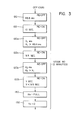
- FIGURE 3 is a flow chart and block diagram of the programmed stall sequence system employed in the preferred embodiment of the present invention;
- FIGURE 4 is a modification of the preferred embodiment of the present invention wherein the vehicle mounted control unit is adapted to be programmed for accepting more than one transmitter for operating the preferred embodiment of the present invention;
- FIGURE 5 is a front plan view of the module constituting the motor vehicle mounted control unit of the preferred embodiment of the present invention;
- FIGURE 6 is a side elevational view of a coded key of the type which is used for the embodiment of the invention as shown in FIGURE 4;
- FIGURE 7 is a block diagram showing the electrical elements of the personal identification device, or PID, employed in the preferred embodiment of the present invention; and,
- FIGURE 8 is a representative coded transmitted signal of the type used in the present invention and as created by the transmitter schematically illustrated in FIGURE 7.
- Referring now to the drawings wherein the showings are for the purpose of illustrating a preferred embodiment of the invention only and not for the purpose of limiting same, FIGURE 1 illustrates a connection of the preferred embodiment of the present invention wherein the
anti-theft control unit 10 is connected in a system including a standardmotor vehicle battery 12 and anignition coil 14.Battery cables coil 14 for the purpose of operating the motor vehicle. As is known, whencoil 14 is inoperative, the internal combustion engine powering the motor vehicle will be rendered inoperative. In accordance with the preferred embodiment of the present invention,control unit 10 includes a microprocessor and is powered by leads 30, 32 formstandard battery 12. Connection ofcontrol unit 10 on a motor vehicle includes mounting the unit by bolts in an inaccessible location. Thebattery cable 20 is then cutadjacent coil 14 to provide spacedends leads 10a, 10b forming the output ofcontrol unit 10, as shown in FIGURE 1. By making the cut in the power supply line ofcoil 14, and providing electrical fasteners at the cuts for joining withleads 10a, 10b,unit 10 is easily installed. This installation can be done by a person with relatively minor knowledge of the electrical system of a motor vehicle.Battery cables battery terminals control unit 10, is easily installed in a motor vehicle with very few tools and a minor amount of technical knowledge. - Referring now to FIGURE 2, a schematic wiring diagram of the
control unit 10 is illustrated, together with the personal identification device or transmitter T, which PID transmits a series of electromagnetic coded signals S at short intervals. Transmitter T is carried by an authorized operator of the motor vehicle onto whichunit 10 is mounted and includes anantenna 50 and aclip 52 for mounting the transmitter onto the person of the authorized operator. Of course, transmitter T could be carried in the clothing of the operator or otherwise carried by the operator to maintain signal S transmitting tounit 10 when the transmitter T is in the vicinity of the motor vehicle. Vicinity is a relative term and is meant to mean preferably approximately 5-20 feet or generally less than about 50 feet from the motor vehicle. After the transmitter T is beyond the vicinity of the vehicle, signal S is no longer available for detection byunit 10. In accordance with the preferred embodiment, the vehicle mountedunit 10 includes adecoder 60 having anantenna 62 and anoutput 64. Signal S has a unique multiple bit digital signal which is transmitted serially and periodically tounit 10. Only this unique coded signal can be recognized and acknowledged bydecoder 60. This concept is standard digital practice. When a signal having the desired unique code set intodecoder 60 is received by the decoder, a signal is transmitted by theoutput 64 to areset timer 70. In practice the timer is formed as part of the microprocessor used incontrol unit 10. Of course, thetimer 70 could be a reset timer formed of discrete circuit components. The timer, in accordance with the preferred embodiment of the invention, produces a logic 1 inoutput 72 when the timer expires without a reset signal inline 64. Expiration time oftimer 70 is, in practice, 2.0 minutes. Consequently, if a signal inline 64 is not received within 2.0 minutes, theoutput line 72 shifts from a first condition allowing operation of the motor vehicle to a second condition indicated as a logic 1. This second condition inhibits operation of the motor vehicle in accordance with the present invention.Output 72 is directed to stage 80 of the microprocessor which identifies whether the motor vehicle is to be operated. Alogic 0 inline 72 is a resetsignal resetting stage 90 of the microprocessor by a logic 1 inline 82. Consequently, whenoutput 72 is in the first condition allowing operation of the vehicle,stage 80 has a logic 1 output inline 82 which resetsstage 90 of the microprocessor inunit 10. Upon receipt of a logic 1 bystage 80, a logic 1 appears inline 84 instead of a logic 1 inline 82. Thus, alogic 0 appears inline 82 and a logic 1 appears inline 84 when a logic 1 appears inline 72. This digital condition initiates the stall sequence described in more detail in FIGURE 3 and implemented instage 90 of the microprocessor. The stall sequence as will be described later, opens and closes the power tocoil 14. This is done in the microprocessor. This function is schematically illustrated as a relay RE having acoil 92 controlled byoutput 94 frommicroprocessor stage 90.Microprocessor stage 90 is the inhibit arrangement for inhibiting the operation of the motor vehicle by gradually stalling the motor vehicle through operation ofstage 90 in the manner illustrated in FIGURE 3. Relay RE is normally closed when the vehicle is to be operated. Relay RE operatesbreaker 100 through acoil 102adjacent lines power breaker 100 is mounted, in the preferred embodiment, withincontrol unit 10. Of course, it could be a separate, discrete component outsideunit 10 if desired.Breaker 100 is normally opened as shown in FIGURE 2. When relay RE is closed,breaker 100 is closed to allow operation of thecoil 14 as long as ignition switch SW is closed. - In operation, so long as transmitter, or personal identification device T, is in the vicinity of
unit 10, a reset signal periodically appears inline 64. This maintainsreset timer stage 70 in its reset condition with alogic 0 inline 72. A logic 1 appears inline 82 fromstage 80 to maintain the stall sequence instage 90 of the microprocessor in the reset condition. A logic 1 appears online 94 closing relay RE and, thus, closingbreaker 100. The motor vehicle operates normally. When the operator leaves the vehicle with transmitter T, a signal is no longer received periodically bydecoder 60. Thus, a reset signal does not periodically appear online 64.Reset timer stage 70 times out shiftingoutput 72 from a first condition allowing operation of the vehicle to a second condition inhibiting operation of the vehicle. This second condition is represented by logic 1 inline 72, which logic causes a logic 1 to appear inline 84. This initiates the stall sequence ofstage 90. The stall sequence, as disclosed in FIGURE 3, ultimately causes a logic 1 to appear inline 94. This permanent or sustained logic 1 opens relay RE. When the relay RE is opened,breaker 100 is opened since it assumes its normal position. Of course, other arrangements for the relay RE andbreaker 100 could be used. A normally opened breaker could be employed if desired. However, the normal position would be indicative of a logic 1 or second condition inline 72. - The stall sequence of
stage 90 is schematically illustrated in FIGURE 3 wherein a logic 1 inline 84 commences the sequence for stalling the vehicle gradually. At the first instance, block 120 creates alogic 0 inline 94. This occurs for 65.6 milliseconds. Such signal opensbreaker 100 as shown in FIGURE 2 for a very short period of time. Thereafter, a logic 1 appears inline 94 for 10.0 seconds. Thus,coil 14 can operate normally for 10 seconds. After 10 seconds, alogic 0 appears inblock 120a for a time Xi. This time is greater than 65.6 milliseconds. Thereafter, a logic 1 appears inline 94 causingcoil 14 to be activated for 9.5 seconds. This sequence betweenblock 120 and block 122 continues gradually increasing the time that the coil is inactive and gradually decreasing the time when the coil is active, until reachingblocks logic 0 remains online 94 andbreaker 100 is maintained opened. The stall sequence could take a variety of configurations. By using the stall sequence, the vehicle shuts down gradually. The vehicle gradually loses power until the vehicle can no longer operate. This allows brakes, power steering, and other accessories to be operative for the purposes of steering the vehicle off the roadway and gradually stopping the vehicle. The person stealing the vehicle and leaving transmitter T behind merely experiences a gradual shut-down of the motor vehicle. This is sufficient to allow parking the vehicle at the side of the roadway. Under no circumstance can the vehicle be moved further. Thus, after two minutes without the transmitter in the vicinity ofunit 10, the vehicle starts into the stall sequence. The stall sequence, in practice, lasts 1.0 minutes. Since the vehicle is normally driven away quite rapidly, the person commandeering the vehicle in a high tension situation will be many blocks from the victim before the vehicle is stalled. - The present invention is particularly applicable for preventing hijacking of a vehicle by stalling the vehicle at a remote location from the actual hijacking location. Of course, when the vehicle is parked and the operator leaves the vehicle, the personal identification device or transmitter T is removed. This causes
unit 10 to shut down the motor vehicle in the parked unattended condition. Consequently,device 10 also performs an anti-theft prevention function. It is possible to useunit 10 to operate auxiliary components. This can be combined with a device for sensing whether the alternator is operating to know whether the vehicle is operating or parked. In normal entry, the transmitter signal is received byunit 10 and the alternator is off. In this instance, an auxiliary system is employed for unlocking the doors and enabling the ignition system byunit 10. If the vehicle is being driven the transmitter in the vehicle and the alternator is operating. Thus,device 10 enables and maintains the ignition system as illustrated in FIGURE 2. When the person exits the vehicle, the PID or transmitter is removed. The alternator had been operating; therefore, after two minutes, the ignition is progressively shut down in accordance with the stall sequence of FIGURE 3. It is possible to apply auxiliary accessories to lock the doors in this situation. If the automobile is hijacked, which indicates a removal of the transmitter while the alternator is operating, the vehicle waits for two minutes before it is stalled in accordance with the sequence of FIGURE 3. Since the transmitter is still gone, remotely connected accessory components can be used to lock the doors, close the windows and, after the stall sequence has been implemented, disconnect the main light switch, raise the head light door, pulse the lights, and pulse a siren to signal the fact that this vehicle is being operated by someone not authorized. When the transmitter is then returned, the stall sequence is immediately deactivated by enabling the ignition. This will stop the pulsing of the lights and operation of the siren, reconnect the main highlights, return the headlamp door to driver control and allow normal driving. All of these functions can be employed by connecting external accessories to an I/O board onunit 10. The board is connected to external relays for sequencing the external accessories in accordance with the existing condition of the vehicle. The existing condition can be determined and identified by the condition of the alternator, in combination with the location of the transmitter or personal identification device T. - Referring now to FIGURE 4, in some instances it is necessary to operate
control unit 10 by more than one transmitter. The several transmitters could be for use with other products manufactured and/or distributed by the entity distributing the present invention. Each of these transmitters TA, TB, Tc and To is illustrated in FIGURE 4. Four decoders 200-206 are provided to give periodic signals inline 64 upon receipt of the specific signal for which the decoders are each set. A decoder will create an output in one of thelines unit 10. Akey decoder 210 identifies the proper key K inserted into one of thekey ports port 120 is first identified as a proper key bydecoder 210. If the proper key is present, asignal light 230 is activated and a coded signal is received online 240 from a particular one of the several transmitters or personal identification devices, as shown in FIGURE 4. By using the proper key K an enable signal appears on one of thelines unit 10 to the particular transmitter in the vicinity of the motor vehicle.Unit 10 operates in accordance with the previous discussion. As one of the transmitters having a code set into one of the decoders 200-206 is brought into the vicinity of the vehicle, the signal S causes periodic pulses inline 64. - In practice, a key similar to the key K illustrated in FIGURE 1 is employed. In that instance, light 235 is mounted on the key itself. Another key arrangement is illustrated in FIGURE 6, wherein key K' has physical decoding dimples or recesses and a light 230' powered by
leads particular unit 10 by the code on the key. In that situation, the decoder corresponding to the key port is loaded with the particular code of one of the transmitters shown in FIGURE 4. Consequently, several transmitters can be employed for operating the anti-theft device constructed in accordance with the present invention. - The small personal identification unit or transmitter T is illustrated in FIGURE 7 wherein the first stage is the "message" stage which creates a continuous signal in
line 300a. Thisstage 300 could also be employed for use with the key K for learning the particular code of transmitter T. Under normal conditions, continuous power is applied throughline 300a to thepulse timer 302. This pulse timer creates a signal inline 302a each 10.1 seconds. This signal is converted to the desired unique coded signal byencoder 304 to produce a series of binary signals which are directed to the 100 kHzoscillator 306. The output of the oscillator is a series of small or long pulses indicative of thelogic 0 and a logic 1, respectively, of a binary coded signal. The coded signal is directed throughline 306a to theantenna driver isolator 308 so that each 10.1 seconds an electromagnetic coded signal unique to transmitter T is transmitted fromantenna 310, illustrated in FIGURE 2 asantenna 50. To prevent radio interference, the signal onantenna 310 is provided with a carrier having a frequency of 418 MHz. The resulting signal is a 100 kHz decoded serial signal with a 418 MHz carrier. This signal occurs each 10.1 seconds to resettiming stage 70 periodically as transmitter T is in the vicinity ofunit 10 on the motor vehicle being controlled. It is possible that other transmitting devices could be employed to periodically reset thetimer 70. The transmitter T as illustrated in FIGURE 5 produces signal S as shown in FIGURE 8 and is the preferred embodiment. This signal has a series of binary numbers defined by short pulses S1, S3 and long pulses S2 and S4.
Claims (80)
Priority Applications (1)
| Application Number | Priority Date | Filing Date | Title |
|---|---|---|---|
| EP03022091A EP1380479B1 (en) | 1993-02-08 | 1994-02-08 | Anti-theft device especially for motor vehicles |
Applications Claiming Priority (2)
| Application Number | Priority Date | Filing Date | Title |
|---|---|---|---|
| US08/014,560 US5604384A (en) | 1993-02-08 | 1993-02-08 | Anti-theft device for motor vehicle |
| US14560 | 1993-02-08 |
Related Child Applications (1)
| Application Number | Title | Priority Date | Filing Date |
|---|---|---|---|
| EP03022091A Division EP1380479B1 (en) | 1993-02-08 | 1994-02-08 | Anti-theft device especially for motor vehicles |
Publications (3)
| Publication Number | Publication Date |
|---|---|
| EP0610902A2 true EP0610902A2 (en) | 1994-08-17 |
| EP0610902A3 EP0610902A3 (en) | 1995-07-05 |
| EP0610902B1 EP0610902B1 (en) | 2003-12-17 |
Family
ID=21766205
Family Applications (2)
| Application Number | Title | Priority Date | Filing Date |
|---|---|---|---|
| EP94101934A Expired - Lifetime EP0610902B1 (en) | 1993-02-08 | 1994-02-08 | Anti-theft device especially for motor vehicles |
| EP03022091A Expired - Lifetime EP1380479B1 (en) | 1993-02-08 | 1994-02-08 | Anti-theft device especially for motor vehicles |
Family Applications After (1)
| Application Number | Title | Priority Date | Filing Date |
|---|---|---|---|
| EP03022091A Expired - Lifetime EP1380479B1 (en) | 1993-02-08 | 1994-02-08 | Anti-theft device especially for motor vehicles |
Country Status (13)
| Country | Link |
|---|---|
| US (2) | US5604384A (en) |
| EP (2) | EP0610902B1 (en) |
| JP (1) | JP2838478B2 (en) |
| KR (1) | KR0160318B1 (en) |
| AT (2) | ATE430072T1 (en) |
| AU (1) | AU666601B2 (en) |
| CA (1) | CA2114612C (en) |
| DE (2) | DE69433417T2 (en) |
| DK (1) | DK1380479T3 (en) |
| ES (2) | ES2326524T3 (en) |
| NO (1) | NO940394L (en) |
| PH (1) | PH30844A (en) |
| UY (1) | UY24095A1 (en) |
Cited By (14)
| Publication number | Priority date | Publication date | Assignee | Title |
|---|---|---|---|---|
| EP0778184A3 (en) * | 1995-12-06 | 1997-07-09 | Alertcall Inc | |
| EP0771703A3 (en) * | 1995-11-06 | 1997-11-05 | DUCATI ENERGIA S.p.A. | Combined electronic ignition and anti-theft alarm system |
| FR2771534A1 (en) * | 1997-11-24 | 1999-05-28 | Valeo Systemes De Fermetures | MOTOR VEHICLE EQUIPPED WITH A SYSTEM FOR DETECTING THE APPROACH OF A USER |
| ES2207411A1 (en) * | 2002-11-11 | 2004-05-16 | Javier Lopez Berlanga | Anti-theft device |
| EP1273492A3 (en) * | 2001-07-05 | 2004-08-04 | Honda Giken Kogyo Kabushiki Kaisha | Remote control lock operation system for vehicles |
| GB2399924A (en) * | 2003-03-25 | 2004-09-29 | Milton Thompson | Security authorisation system requires wireless communication link between complentary parts |
| US6819009B2 (en) | 2000-04-12 | 2004-11-16 | Carl Ellingsworth | Method and apparatus for preventing unauthorized access to a vehicle |
| WO2005019005A3 (en) * | 2003-08-13 | 2005-05-12 | Idas Informations Daten Und Au | Method and device for securing a vehicle against theft |
| GB2396238B (en) * | 2002-12-11 | 2006-05-24 | Nippon Yusoki Co Ltd | Unqualified person driving prevention apparatus for vehicle |
| EP1762447A3 (en) * | 2003-08-13 | 2007-05-23 | Idas Informations- Daten- und Automationssysteme GmbH | Method and dveice for securing a vehicle against theft |
| US8659387B2 (en) | 2005-07-13 | 2014-02-25 | Komatsu Utility Co., Ltd. | Operation permission control device and machine having the same mounted thereon |
| ITGE20130026A1 (en) * | 2013-02-28 | 2014-08-29 | Salvatore Guarneri | ALARM DEVICE FOR VEHICLES |
| CN106740683A (en) * | 2017-03-03 | 2017-05-31 | 铁将军汽车电子有限公司 | Vehicle unlocking method and system based on CAN bus |
| WO2021104850A1 (en) * | 2019-11-26 | 2021-06-03 | Bayerische Motoren Werke Aktiengesellschaft | Method for operating a vehicle, device and vehicle |
Families Citing this family (42)
| Publication number | Priority date | Publication date | Assignee | Title |
|---|---|---|---|---|
| DE4440975C2 (en) * | 1994-11-17 | 1997-06-12 | Daimler Benz Ag | Third-party protection device for a motor vehicle |
| JP3292025B2 (en) * | 1996-02-27 | 2002-06-17 | 日産自動車株式会社 | Automatic locking device for keyless system for vehicles |
| US5977654A (en) * | 1997-09-25 | 1999-11-02 | Johnson Controls Technology Company | Anti-theft System for disabling a vehicle engine that includes a multi-contact switch for disconnecting the battery and loading the vehicle electrical system |
| US5965954A (en) * | 1997-09-25 | 1999-10-12 | Johnson Controls Technology Company | Anti-theft system for disabling a vehicle engine |
| US5937823A (en) * | 1998-01-05 | 1999-08-17 | Reeder; Allan | Safely disabling a land vehicle using a selective call radio signal |
| US6265787B1 (en) * | 1999-01-28 | 2001-07-24 | Richard T. Downey | Vehicle anti-theft system |
| EP1028041A3 (en) * | 1999-02-10 | 2001-10-24 | Michael Martin Machala | An apparatus and method for electronically delaying or stopping vehicles |
| US6531955B1 (en) * | 1999-03-23 | 2003-03-11 | Henry Tzvi Brendzel | Arrangement for prevention of motor vehicle thefts |
| US20030169150A1 (en) * | 1999-03-23 | 2003-09-11 | Brendzel Henry Tzvi | Arrangement for prevention of motor vehicle thefts |
| US6109076A (en) * | 1999-05-06 | 2000-08-29 | Master Lock Company | Automobile and airbag anti-theft device |
| DE10059991A1 (en) * | 2000-12-02 | 2002-06-06 | Bosch Gmbh Robert | Device for the keyless operation of a motor vehicle |
| USD493691S1 (en) | 2001-10-19 | 2004-08-03 | Robert A. Vito | Lock assembly |
| US6679089B2 (en) | 2001-10-19 | 2004-01-20 | Robert A. Vito | Type of automobile anti-theft device |
| USD493354S1 (en) | 2001-10-19 | 2004-07-27 | Robert A. Vito | Lock assembly component |
| JP3847140B2 (en) * | 2001-10-30 | 2006-11-15 | 株式会社モリック | Anti-theft device for vehicles |
| US6460385B1 (en) | 2001-12-07 | 2002-10-08 | Robert A. Vito | Column lock device |
| USD465721S1 (en) | 2001-12-07 | 2002-11-19 | Robert A. Vito | Anti-theft device |
| USD458529S1 (en) | 2001-12-07 | 2002-06-11 | Robert A. Vito | Anti-theft device |
| US6516642B1 (en) | 2001-12-07 | 2003-02-11 | Robert A. Vito | Column security device |
| JP4519645B2 (en) * | 2002-07-12 | 2010-08-04 | プリヴァリス・インコーポレーテッド | Personal authentication software and system for travel privilege assignment and verification |
| US6857496B2 (en) * | 2002-09-03 | 2005-02-22 | Trw Inc. | Vehicle steering apparatus with anti-steer security device |
| US7973649B2 (en) * | 2002-09-10 | 2011-07-05 | Lojack Operating Company Lp | Method of an apparatus for sensing the unauthorized movement of vehicles and the like and generating an alarm or warning of vehicle theft |
| US8749345B2 (en) * | 2003-03-25 | 2014-06-10 | Milton Thompson | Security authorization system |
| US7197379B2 (en) * | 2003-04-25 | 2007-03-27 | Donald Wayne Jackson | Anti-theft device for motorized vehicles |
| CN1299937C (en) * | 2003-12-30 | 2007-02-14 | 厦门雅迅网络股份有限公司 | Automatic defence supplying and withdrawing method for automobile anti-theft alarm system |
| DE602004012163T2 (en) * | 2004-01-12 | 2009-04-16 | LoJack Corp., Westwood | DETECTING A VEHICLE MOTION |
| US20060238299A1 (en) * | 2005-04-22 | 2006-10-26 | Downey Richard T | Electrical enabling device |
| CA2509804A1 (en) * | 2005-06-15 | 2006-12-15 | Kolombo Technologies Ltee | Remote and real time management and intervention system for industrial vehicles for road transport |
| JP4783643B2 (en) * | 2006-02-06 | 2011-09-28 | 株式会社小松製作所 | MOBILE BODY MONITORING DEVICE AND MOBILE BODY MONITORING SYSTEM |
| JP4835239B2 (en) * | 2006-04-06 | 2011-12-14 | スズキ株式会社 | Motorcycle |
| JP2011126293A (en) * | 2008-03-28 | 2011-06-30 | Yamaha Motor Electronics Co Ltd | Theft deterrent device |
| DE102009011088A1 (en) * | 2009-03-03 | 2010-09-09 | Volkswagen Ag | Method and device for controlling a vehicle movement possibility and / or a closure device |
| KR101927217B1 (en) * | 2011-05-03 | 2018-12-10 | 엘지이노텍 주식회사 | Method for controlling smartkey system for door lock |
| US20130033369A1 (en) * | 2011-08-02 | 2013-02-07 | Burnett Ronald A | Electronic anti-theft apparatus and system for vehicles |
| US20140327555A1 (en) * | 2013-04-23 | 2014-11-06 | Canary Connect, Inc. | Monitoring & security systems and methods with learning capabilities |
| DE102013020333A1 (en) * | 2013-12-04 | 2015-06-11 | Daimler Ag | System and method for decommissioning an illegally used vehicle |
| US10239476B2 (en) * | 2013-12-23 | 2019-03-26 | Lippert Components, Inc. | System for inhibiting operation of a vehicle-based device while the vehicle is in motion |
| US9663113B2 (en) * | 2014-10-06 | 2017-05-30 | Preventext Llc | Integrated vehicle monitoring and control |
| US11194350B2 (en) * | 2018-10-17 | 2021-12-07 | International Business Machines Corporation | Navigation of an autonomous vehicle for following individuals |
| US20200231119A1 (en) * | 2019-01-22 | 2020-07-23 | Ali Mahmood | Anti-Theft Vehicle Shutdown Kit |
| US12474714B2 (en) | 2021-06-10 | 2025-11-18 | Stop Technologies, Inc. | System and methodology that facilitates taking control of a vehicle from a remote device |
| JP2025034745A (en) * | 2023-08-31 | 2025-03-13 | スズキ株式会社 | Vehicle anti-theft systems |
Family Cites Families (55)
| Publication number | Priority date | Publication date | Assignee | Title |
|---|---|---|---|---|
| US3646515A (en) * | 1970-03-02 | 1972-02-29 | Frank Vodehnal | Vehicular safety and remote control system |
| US3665386A (en) * | 1970-12-18 | 1972-05-23 | Dynamics Corp America | Anti-hijack system for vehicles |
| US3788422A (en) * | 1972-10-27 | 1974-01-29 | Gmc Co | Anti-theft system including a pushbutton electronic combination ignition lock and transmission shift control |
| US4004273A (en) * | 1975-08-28 | 1977-01-18 | Kalogerson Thomas A | Engine speed responsive anti-theft device for vehicle |
| US4023138A (en) * | 1975-11-17 | 1977-05-10 | Joseph Ballin | Vehicle theft prevention system |
| US4101873A (en) * | 1976-01-26 | 1978-07-18 | Benjamin Ernest Anderson | Device to locate commonly misplaced objects |
| US4143368A (en) * | 1977-12-05 | 1979-03-06 | General Motors Corporation | Vehicle operator security system |
| FR2423015A1 (en) * | 1978-04-14 | 1979-11-09 | M B Ste Civile | Antitheft alarm triggering and neutralising system - uses low power portable transmitter attached to key-ring to communicate with receiver in vehicle or building |
| US4292620A (en) * | 1979-06-13 | 1981-09-29 | Pagane Warren H | Fuel level monitoring engine control and vehicle theft inhibiting device |
| US4260982A (en) * | 1979-10-25 | 1981-04-07 | Debenedictis Angelo P | Pulse code modulation responsive alarm system |
| DE3048861A1 (en) * | 1980-07-14 | 1982-07-15 | John L. Denver Col. Royster | SECURITY SYSTEM |
| FR2493246A1 (en) * | 1980-11-03 | 1982-05-07 | Prost Albert | Centralised locking system for building or automobile - operated automatically in conjunction with anti-theft circuit requiring manual setting |
| JPS58174357U (en) * | 1982-05-18 | 1983-11-21 | 橋爪 外信 | car anti-theft device |
| US4452197A (en) * | 1982-08-11 | 1984-06-05 | Weber Harold J | Vehicle anti-theft ignition foiling device |
| US4598275A (en) * | 1983-05-09 | 1986-07-01 | Marc Industries Incorporated | Movement monitor |
| US4754255A (en) * | 1984-03-12 | 1988-06-28 | Sanders Rudy T | User identifying vehicle control and security device |
| US4675656A (en) * | 1984-03-16 | 1987-06-23 | Narcisse Bernadine O | Out-of-range personnel monitor and alarm |
| US4598272A (en) * | 1984-08-06 | 1986-07-01 | Cox Randall P | Electronic monitoring apparatus |
| JPS61215457A (en) * | 1985-03-22 | 1986-09-25 | Aisin Seiki Co Ltd | Onboard ignition device |
| JPS61161056U (en) * | 1985-03-28 | 1986-10-06 | ||
| JPH0727508B2 (en) * | 1985-07-23 | 1995-03-29 | 富士通株式会社 | Bus order retention control method |
| JPS6222170U (en) * | 1985-07-25 | 1987-02-10 | ||
| JPS6237479A (en) * | 1985-08-12 | 1987-02-18 | 日産自動車株式会社 | Wireless type locking and releasing controller |
| JPS6271070U (en) * | 1985-10-24 | 1987-05-06 | ||
| GR861382B (en) * | 1985-11-13 | 1987-02-06 | Pelta Elettronica S P A | System for remote control of the antitheft protection devices of a property |
| JPS62203854A (en) * | 1986-03-03 | 1987-09-08 | Matsushita Electric Works Ltd | Card system for automobile |
| JPS63130900U (en) * | 1987-02-16 | 1988-08-26 | ||
| US4785291A (en) * | 1987-03-06 | 1988-11-15 | Hawthorne Candy C | Distance monitor especially for child surveillance |
| US4987406A (en) * | 1987-04-13 | 1991-01-22 | Reid Philip L | Security system for electrical appliances and other items with electrical circuitry |
| JPS6474145A (en) * | 1987-09-17 | 1989-03-20 | Nippon Kikaku Kk | Driver's license inserting engine starting control device |
| US4898010A (en) * | 1987-10-28 | 1990-02-06 | Nissan Motor Company, Limited | Keyless entry system for automotive vehicles |
| JPH01165750U (en) * | 1988-05-13 | 1989-11-20 | ||
| US4942393A (en) * | 1988-05-27 | 1990-07-17 | Lectron Products, Inc. | Passive keyless entry system |
| JPH0223383A (en) * | 1988-07-12 | 1990-01-25 | Japan Metaritsuku:Kk | Secrecy leak prevention system using copying machine and copying paper |
| JPH0291864A (en) * | 1988-09-27 | 1990-03-30 | Nec Ibaraki Ltd | Magnetic disk device |
| US4924206A (en) * | 1988-12-05 | 1990-05-08 | Ayers Robert F | Car security system and method |
| US4866296A (en) * | 1988-12-09 | 1989-09-12 | Thomas Stephen R | Circuit interrupt system |
| JPH0291864U (en) * | 1988-12-29 | 1990-07-20 | ||
| US4992670A (en) * | 1989-04-03 | 1991-02-12 | Pastor David E | Ignition disabling anti-theft device |
| JPH02299955A (en) * | 1989-05-15 | 1990-12-12 | Motohiro Gotanda | Burglar preventing device for automobile |
| DE4019478A1 (en) * | 1989-06-20 | 1991-01-10 | Honda Motor Co Ltd | ELECTRIC POWER SUPPLY CONTROL UNIT FOR A MOTOR VEHICLE |
| JPH0386869A (en) * | 1989-08-30 | 1991-04-11 | Kanebo Ltd | Production of quinazoline derivative |
| JPH03148352A (en) * | 1989-11-02 | 1991-06-25 | Nissan Motor Co Ltd | Keyless controller for vehicle |
| JP2507815B2 (en) * | 1989-11-02 | 1996-06-19 | 日産自動車株式会社 | Vehicleless controller |
| JP2593566B2 (en) * | 1989-12-18 | 1997-03-26 | アルパイン株式会社 | In-vehicle security device |
| JPH03208974A (en) * | 1990-01-10 | 1991-09-12 | Oki Electric Ind Co Ltd | Locking device for automobile |
| US5229375A (en) * | 1990-08-01 | 1993-07-20 | Scripps Clinic And Research Foundation | Phosphene oxide-terminated allene-ene-yne dna-cleaving, antitumor and antibiotic molecules |
| IT221193Z2 (en) * | 1990-08-10 | 1994-02-16 | Girotto Pietro | AUTOMATIC CONTROL DEVICE OF AN ANTI-THEFT SYSTEM |
| DE4030880A1 (en) * | 1990-09-29 | 1992-04-09 | Fischer Lagertechnik | Electric goods transport vehicle security system - disables vehicle control circuit when out of range of remote control transmitter carried by operator |
| US5132660A (en) * | 1991-01-09 | 1992-07-21 | Nutek Corporation | Vehicle security system |
| JPH04331647A (en) * | 1991-04-30 | 1992-11-19 | Honda Motor Co Ltd | Power supply control unit for vehicle |
| US5412370A (en) * | 1992-10-23 | 1995-05-02 | Berman; Leonard C. | Car theft prevention device |
| US5444430A (en) * | 1993-01-04 | 1995-08-22 | Mcshane; Richard | Motor vehicle security system |
| US5349329B1 (en) * | 1993-05-07 | 1996-09-10 | Ideaz International Inc | Vehicle security apparatus and method |
| JP3086869U (en) * | 2001-12-21 | 2002-07-05 | ユーザー株式会社 | floor mat |
-
1993
- 1993-02-08 US US08/014,560 patent/US5604384A/en not_active Expired - Lifetime
-
1994
- 1994-01-14 PH PH47616A patent/PH30844A/en unknown
- 1994-01-31 CA CA002114612A patent/CA2114612C/en not_active Expired - Fee Related
- 1994-02-03 AU AU54907/94A patent/AU666601B2/en not_active Ceased
- 1994-02-04 JP JP4299994A patent/JP2838478B2/en not_active Expired - Fee Related
- 1994-02-05 KR KR1019940002146A patent/KR0160318B1/en not_active Expired - Fee Related
- 1994-02-07 NO NO940394A patent/NO940394L/en not_active Application Discontinuation
- 1994-02-08 DK DK03022091T patent/DK1380479T3/en active
- 1994-02-08 ES ES03022091T patent/ES2326524T3/en not_active Expired - Lifetime
- 1994-02-08 AT AT03022091T patent/ATE430072T1/en not_active IP Right Cessation
- 1994-02-08 ES ES94101934T patent/ES2213145T3/en not_active Expired - Lifetime
- 1994-02-08 EP EP94101934A patent/EP0610902B1/en not_active Expired - Lifetime
- 1994-02-08 DE DE69433417T patent/DE69433417T2/en not_active Expired - Lifetime
- 1994-02-08 EP EP03022091A patent/EP1380479B1/en not_active Expired - Lifetime
- 1994-02-08 DE DE69435207T patent/DE69435207D1/en not_active Expired - Lifetime
- 1994-02-08 AT AT94101934T patent/ATE256582T1/en not_active IP Right Cessation
-
1995
- 1995-08-07 US US08/512,065 patent/US6400042B1/en not_active Expired - Fee Related
- 1995-11-21 UY UY24095A patent/UY24095A1/en not_active IP Right Cessation
Cited By (20)
| Publication number | Priority date | Publication date | Assignee | Title |
|---|---|---|---|---|
| EP0771703A3 (en) * | 1995-11-06 | 1997-11-05 | DUCATI ENERGIA S.p.A. | Combined electronic ignition and anti-theft alarm system |
| EP0778184A3 (en) * | 1995-12-06 | 1997-07-09 | Alertcall Inc | |
| FR2771534A1 (en) * | 1997-11-24 | 1999-05-28 | Valeo Systemes De Fermetures | MOTOR VEHICLE EQUIPPED WITH A SYSTEM FOR DETECTING THE APPROACH OF A USER |
| US6081185A (en) * | 1997-11-24 | 2000-06-27 | Valeo Securite Habitacle | Motor vehicle equipped with a system for detecting the approach of a user |
| US6819009B2 (en) | 2000-04-12 | 2004-11-16 | Carl Ellingsworth | Method and apparatus for preventing unauthorized access to a vehicle |
| US7071819B2 (en) | 2001-07-05 | 2006-07-04 | Honda Giken Kogyo Kabushiki Kaisha | Remote control lock operation system for vehicles |
| EP1273492A3 (en) * | 2001-07-05 | 2004-08-04 | Honda Giken Kogyo Kabushiki Kaisha | Remote control lock operation system for vehicles |
| ES2207411A1 (en) * | 2002-11-11 | 2004-05-16 | Javier Lopez Berlanga | Anti-theft device |
| GB2396238B (en) * | 2002-12-11 | 2006-05-24 | Nippon Yusoki Co Ltd | Unqualified person driving prevention apparatus for vehicle |
| GB2399924A (en) * | 2003-03-25 | 2004-09-29 | Milton Thompson | Security authorisation system requires wireless communication link between complentary parts |
| US7551064B2 (en) | 2003-08-13 | 2009-06-23 | Idas Informations-Daten- und Automationssysteme GmbH | Method and device for securing a vehicle against theft |
| EP1762447A3 (en) * | 2003-08-13 | 2007-05-23 | Idas Informations- Daten- und Automationssysteme GmbH | Method and dveice for securing a vehicle against theft |
| WO2005019005A3 (en) * | 2003-08-13 | 2005-05-12 | Idas Informations Daten Und Au | Method and device for securing a vehicle against theft |
| US8659387B2 (en) | 2005-07-13 | 2014-02-25 | Komatsu Utility Co., Ltd. | Operation permission control device and machine having the same mounted thereon |
| ITGE20130026A1 (en) * | 2013-02-28 | 2014-08-29 | Salvatore Guarneri | ALARM DEVICE FOR VEHICLES |
| WO2014131501A1 (en) | 2013-02-28 | 2014-09-04 | Guarneri Salvatore | Vehicle alarm device. |
| US9776598B2 (en) | 2013-02-28 | 2017-10-03 | Salvatore GUARNERI | Vehicle alarm device |
| CN106740683A (en) * | 2017-03-03 | 2017-05-31 | 铁将军汽车电子有限公司 | Vehicle unlocking method and system based on CAN bus |
| WO2021104850A1 (en) * | 2019-11-26 | 2021-06-03 | Bayerische Motoren Werke Aktiengesellschaft | Method for operating a vehicle, device and vehicle |
| US12122323B2 (en) | 2019-11-26 | 2024-10-22 | Bayerische Motoren Werke Aktiengesellschaft | Method for operating a vehicle, device and vehicle |
Also Published As
| Publication number | Publication date |
|---|---|
| UY24095A1 (en) | 1996-01-15 |
| CA2114612A1 (en) | 1994-08-09 |
| DK1380479T3 (en) | 2009-08-24 |
| US5604384A (en) | 1997-02-18 |
| NO940394L (en) | 1994-08-09 |
| JP2838478B2 (en) | 1998-12-16 |
| ATE430072T1 (en) | 2009-05-15 |
| AU5490794A (en) | 1994-09-22 |
| EP0610902A3 (en) | 1995-07-05 |
| ES2213145T3 (en) | 2004-08-16 |
| DE69433417D1 (en) | 2004-01-29 |
| EP0610902B1 (en) | 2003-12-17 |
| EP1380479A2 (en) | 2004-01-14 |
| DE69433417T2 (en) | 2004-10-21 |
| US6400042B1 (en) | 2002-06-04 |
| EP1380479B1 (en) | 2009-04-29 |
| AU666601B2 (en) | 1996-02-15 |
| KR940019534A (en) | 1994-09-14 |
| EP1380479A3 (en) | 2004-01-21 |
| JPH06340245A (en) | 1994-12-13 |
| ES2326524T3 (en) | 2009-10-14 |
| DE69435207D1 (en) | 2009-06-10 |
| PH30844A (en) | 1997-11-05 |
| KR0160318B1 (en) | 1998-12-15 |
| NO940394D0 (en) | 1994-02-07 |
| CA2114612C (en) | 1998-09-22 |
| ATE256582T1 (en) | 2004-01-15 |
Similar Documents
| Publication | Publication Date | Title |
|---|---|---|
| US5604384A (en) | Anti-theft device for motor vehicle | |
| US5382948A (en) | Vehicular security system with remote signalling for auto carjacking functions | |
| US6028505A (en) | Electronic vehicle security system with remote control | |
| US5307048A (en) | Vehicle security system including an anti-carjacking system | |
| KR100345886B1 (en) | Vehicle alarm system | |
| JP2617426B2 (en) | Motor vehicle self-storage anti-theft device | |
| US5811886A (en) | Anti-carjacking apparatus | |
| US6781507B1 (en) | Remote start, passive anti theft security system | |
| EP0627998B1 (en) | A method and arrangement for remotely controlling one or more functions of a motor-driven vehicle | |
| US5412378A (en) | Antitheft protection of devices | |
| US5453730A (en) | Auto anti-theft system | |
| US20030222757A1 (en) | Countermeasure system and method for vehicle passive entry system | |
| US5850173A (en) | Vehicle alarm system | |
| US5539377A (en) | Vehicle security system | |
| US5463372A (en) | Self-set vehicle anti-theft/anti-hijacking system with partial disablement followed by complete shutdown | |
| US5506562A (en) | Apparatus and method for disabling an internal combustion engine from a remote location | |
| US4262279A (en) | Alarm system for use in a vehicle and method | |
| US5760680A (en) | Vehicle security device | |
| HK1010713A (en) | Anti-theft device especially for motor vehicles | |
| US4297674A (en) | Passive security device | |
| RU2179122C1 (en) | Method of prevention of unauthorized use of vehicle | |
| CN1125671A (en) | Anti-theft device for motor vehicle | |
| WO1993004899A1 (en) | Passive vehicular theft deterrent system and method | |
| CA2142500A1 (en) | Anti-theft or anti-hijacking device for vehicles | |
| KR19980060122A (en) | Anti-theft device using image transmission |
Legal Events
| Date | Code | Title | Description |
|---|---|---|---|
| PUAI | Public reference made under article 153(3) epc to a published international application that has entered the european phase |
Free format text: ORIGINAL CODE: 0009012 |
|
| 17P | Request for examination filed |
Effective date: 19940308 |
|
| AK | Designated contracting states |
Kind code of ref document: A2 Designated state(s): AT BE CH DE DK ES FR GB GR IE IT LI LU MC NL PT SE |
|
| PUAL | Search report despatched |
Free format text: ORIGINAL CODE: 0009013 |
|
| K1C3 | Correction of patent application (complete document) published |
Effective date: 19940817 |
|
| AK | Designated contracting states |
Kind code of ref document: A3 Designated state(s): AT BE CH DE DK ES FR GB GR IE IT LI LU MC NL PT SE |
|
| 17Q | First examination report despatched |
Effective date: 19961018 |
|
| RAP1 | Party data changed (applicant data changed or rights of an application transferred) |
Owner name: WINNER INTERNATIONAL ROYALTY LLC |
|
| GRAH | Despatch of communication of intention to grant a patent |
Free format text: ORIGINAL CODE: EPIDOS IGRA |
|
| GRAS | Grant fee paid |
Free format text: ORIGINAL CODE: EPIDOSNIGR3 |
|
| GRAA | (expected) grant |
Free format text: ORIGINAL CODE: 0009210 |
|
| AK | Designated contracting states |
Kind code of ref document: B1 Designated state(s): AT BE CH DE DK ES FR GB GR IE IT LI LU MC NL PT SE |
|
| PG25 | Lapsed in a contracting state [announced via postgrant information from national office to epo] |
Ref country code: NL Free format text: LAPSE BECAUSE OF FAILURE TO SUBMIT A TRANSLATION OF THE DESCRIPTION OR TO PAY THE FEE WITHIN THE PRESCRIBED TIME-LIMIT Effective date: 20031217 Ref country code: LI Free format text: LAPSE BECAUSE OF FAILURE TO SUBMIT A TRANSLATION OF THE DESCRIPTION OR TO PAY THE FEE WITHIN THE PRESCRIBED TIME-LIMIT Effective date: 20031217 Ref country code: CH Free format text: LAPSE BECAUSE OF FAILURE TO SUBMIT A TRANSLATION OF THE DESCRIPTION OR TO PAY THE FEE WITHIN THE PRESCRIBED TIME-LIMIT Effective date: 20031217 Ref country code: BE Free format text: LAPSE BECAUSE OF FAILURE TO SUBMIT A TRANSLATION OF THE DESCRIPTION OR TO PAY THE FEE WITHIN THE PRESCRIBED TIME-LIMIT Effective date: 20031217 Ref country code: AT Free format text: LAPSE BECAUSE OF FAILURE TO SUBMIT A TRANSLATION OF THE DESCRIPTION OR TO PAY THE FEE WITHIN THE PRESCRIBED TIME-LIMIT Effective date: 20031217 |
|
| REG | Reference to a national code |
Ref country code: GB Ref legal event code: FG4D |
|
| REG | Reference to a national code |
Ref country code: CH Ref legal event code: EP |
|
| REG | Reference to a national code |
Ref country code: IE Ref legal event code: FG4D |
|
| REF | Corresponds to: |
Ref document number: 69433417 Country of ref document: DE Date of ref document: 20040129 Kind code of ref document: P |
|
| PG25 | Lapsed in a contracting state [announced via postgrant information from national office to epo] |
Ref country code: LU Free format text: LAPSE BECAUSE OF NON-PAYMENT OF DUE FEES Effective date: 20040208 |
|
| PG25 | Lapsed in a contracting state [announced via postgrant information from national office to epo] |
Ref country code: IE Free format text: LAPSE BECAUSE OF NON-PAYMENT OF DUE FEES Effective date: 20040209 |
|
| PG25 | Lapsed in a contracting state [announced via postgrant information from national office to epo] |
Ref country code: MC Free format text: LAPSE BECAUSE OF NON-PAYMENT OF DUE FEES Effective date: 20040228 |
|
| PG25 | Lapsed in a contracting state [announced via postgrant information from national office to epo] |
Ref country code: SE Free format text: LAPSE BECAUSE OF FAILURE TO SUBMIT A TRANSLATION OF THE DESCRIPTION OR TO PAY THE FEE WITHIN THE PRESCRIBED TIME-LIMIT Effective date: 20040317 Ref country code: GR Free format text: LAPSE BECAUSE OF FAILURE TO SUBMIT A TRANSLATION OF THE DESCRIPTION OR TO PAY THE FEE WITHIN THE PRESCRIBED TIME-LIMIT Effective date: 20040317 Ref country code: DK Free format text: LAPSE BECAUSE OF FAILURE TO SUBMIT A TRANSLATION OF THE DESCRIPTION OR TO PAY THE FEE WITHIN THE PRESCRIBED TIME-LIMIT Effective date: 20040317 |
|
| NLV1 | Nl: lapsed or annulled due to failure to fulfill the requirements of art. 29p and 29m of the patents act | ||
| REG | Reference to a national code |
Ref country code: CH Ref legal event code: PL |
|
| REG | Reference to a national code |
Ref country code: ES Ref legal event code: FG2A Ref document number: 2213145 Country of ref document: ES Kind code of ref document: T3 |
|
| ET | Fr: translation filed | ||
| PLBE | No opposition filed within time limit |
Free format text: ORIGINAL CODE: 0009261 |
|
| STAA | Information on the status of an ep patent application or granted ep patent |
Free format text: STATUS: NO OPPOSITION FILED WITHIN TIME LIMIT |
|
| REG | Reference to a national code |
Ref country code: IE Ref legal event code: MM4A |
|
| 26N | No opposition filed |
Effective date: 20040920 |
|
| REG | Reference to a national code |
Ref country code: HK Ref legal event code: WD Ref document number: 1010713 Country of ref document: HK |
|
| PG25 | Lapsed in a contracting state [announced via postgrant information from national office to epo] |
Ref country code: PT Free format text: LAPSE BECAUSE OF NON-PAYMENT OF DUE FEES Effective date: 20040517 |
|
| PGFP | Annual fee paid to national office [announced via postgrant information from national office to epo] |
Ref country code: ES Payment date: 20100219 Year of fee payment: 17 |
|
| PGFP | Annual fee paid to national office [announced via postgrant information from national office to epo] |
Ref country code: IT Payment date: 20100227 Year of fee payment: 17 Ref country code: FR Payment date: 20100315 Year of fee payment: 17 |
|
| PGFP | Annual fee paid to national office [announced via postgrant information from national office to epo] |
Ref country code: GB Payment date: 20100219 Year of fee payment: 17 |
|
| PGFP | Annual fee paid to national office [announced via postgrant information from national office to epo] |
Ref country code: DE Payment date: 20100428 Year of fee payment: 17 |
|
| GBPC | Gb: european patent ceased through non-payment of renewal fee |
Effective date: 20110208 |
|
| REG | Reference to a national code |
Ref country code: FR Ref legal event code: ST Effective date: 20111102 |
|
| PG25 | Lapsed in a contracting state [announced via postgrant information from national office to epo] |
Ref country code: IT Free format text: LAPSE BECAUSE OF NON-PAYMENT OF DUE FEES Effective date: 20110208 |
|
| REG | Reference to a national code |
Ref country code: DE Ref legal event code: R119 Ref document number: 69433417 Country of ref document: DE Effective date: 20110901 |
|
| PG25 | Lapsed in a contracting state [announced via postgrant information from national office to epo] |
Ref country code: FR Free format text: LAPSE BECAUSE OF NON-PAYMENT OF DUE FEES Effective date: 20110228 |
|
| PG25 | Lapsed in a contracting state [announced via postgrant information from national office to epo] |
Ref country code: GB Free format text: LAPSE BECAUSE OF NON-PAYMENT OF DUE FEES Effective date: 20110208 |
|
| REG | Reference to a national code |
Ref country code: ES Ref legal event code: FD2A Effective date: 20120411 |
|
| PG25 | Lapsed in a contracting state [announced via postgrant information from national office to epo] |
Ref country code: ES Free format text: LAPSE BECAUSE OF NON-PAYMENT OF DUE FEES Effective date: 20110209 |
|
| PG25 | Lapsed in a contracting state [announced via postgrant information from national office to epo] |
Ref country code: DE Free format text: LAPSE BECAUSE OF NON-PAYMENT OF DUE FEES Effective date: 20110901 |