EP0608946A2 - Einrichtung zum Aufzeichnen eines Videosignals und eines entsprechenden Tonsignals in Schrägspuren auf einem longitudinalen magnetischen Aufzeichnungsträger und mittels der Einrichtung hergestellte Aufzeichnungsträger - Google Patents
Einrichtung zum Aufzeichnen eines Videosignals und eines entsprechenden Tonsignals in Schrägspuren auf einem longitudinalen magnetischen Aufzeichnungsträger und mittels der Einrichtung hergestellte Aufzeichnungsträger Download PDFInfo
- Publication number
- EP0608946A2 EP0608946A2 EP94200152A EP94200152A EP0608946A2 EP 0608946 A2 EP0608946 A2 EP 0608946A2 EP 94200152 A EP94200152 A EP 94200152A EP 94200152 A EP94200152 A EP 94200152A EP 0608946 A2 EP0608946 A2 EP 0608946A2
- Authority
- EP
- European Patent Office
- Prior art keywords
- signal
- disparity
- tracking
- track
- tracking tone
- Prior art date
- Legal status (The legal status is an assumption and is not a legal conclusion. Google has not performed a legal analysis and makes no representation as to the accuracy of the status listed.)
- Withdrawn
Links
Images


Classifications
-
- G—PHYSICS
- G11—INFORMATION STORAGE
- G11B—INFORMATION STORAGE BASED ON RELATIVE MOVEMENT BETWEEN RECORD CARRIER AND TRANSDUCER
- G11B27/00—Editing; Indexing; Addressing; Timing or synchronising; Monitoring; Measuring tape travel
- G11B27/10—Indexing; Addressing; Timing or synchronising; Measuring tape travel
- G11B27/19—Indexing; Addressing; Timing or synchronising; Measuring tape travel by using information detectable on the record carrier
- G11B27/28—Indexing; Addressing; Timing or synchronising; Measuring tape travel by using information detectable on the record carrier by using information signals recorded by the same method as the main recording
- G11B27/30—Indexing; Addressing; Timing or synchronising; Measuring tape travel by using information detectable on the record carrier by using information signals recorded by the same method as the main recording on the same track as the main recording
- G11B27/309—Table of contents
-
- G—PHYSICS
- G11—INFORMATION STORAGE
- G11B—INFORMATION STORAGE BASED ON RELATIVE MOVEMENT BETWEEN RECORD CARRIER AND TRANSDUCER
- G11B15/00—Driving, starting or stopping record carriers of filamentary or web form; Driving both such record carriers and heads; Guiding such record carriers or containers therefor; Control thereof; Control of operating function
- G11B15/18—Driving; Starting; Stopping; Arrangements for control or regulation thereof
- G11B15/46—Controlling, regulating, or indicating speed
- G11B15/463—Controlling, regulating, or indicating speed by using pilot tracking tones embedded in binary coded signals, e.g. using DSV/CDS values of coded signals
-
- G—PHYSICS
- G11—INFORMATION STORAGE
- G11B—INFORMATION STORAGE BASED ON RELATIVE MOVEMENT BETWEEN RECORD CARRIER AND TRANSDUCER
- G11B27/00—Editing; Indexing; Addressing; Timing or synchronising; Monitoring; Measuring tape travel
- G11B27/10—Indexing; Addressing; Timing or synchronising; Measuring tape travel
- G11B27/19—Indexing; Addressing; Timing or synchronising; Measuring tape travel by using information detectable on the record carrier
- G11B27/28—Indexing; Addressing; Timing or synchronising; Measuring tape travel by using information detectable on the record carrier by using information signals recorded by the same method as the main recording
- G11B27/30—Indexing; Addressing; Timing or synchronising; Measuring tape travel by using information detectable on the record carrier by using information signals recorded by the same method as the main recording on the same track as the main recording
- G11B27/3027—Indexing; Addressing; Timing or synchronising; Measuring tape travel by using information detectable on the record carrier by using information signals recorded by the same method as the main recording on the same track as the main recording used signal is digitally coded
- G11B27/3063—Subcodes
-
- H—ELECTRICITY
- H04—ELECTRIC COMMUNICATION TECHNIQUE
- H04N—PICTORIAL COMMUNICATION, e.g. TELEVISION
- H04N5/00—Details of television systems
- H04N5/76—Television signal recording
- H04N5/91—Television signal processing therefor
- H04N5/92—Transformation of the television signal for recording, e.g. modulation, frequency changing; Inverse transformation for playback
- H04N5/926—Transformation of the television signal for recording, e.g. modulation, frequency changing; Inverse transformation for playback by pulse code modulation
- H04N5/9265—Transformation of the television signal for recording, e.g. modulation, frequency changing; Inverse transformation for playback by pulse code modulation with processing of the sound signal
-
- G—PHYSICS
- G11—INFORMATION STORAGE
- G11B—INFORMATION STORAGE BASED ON RELATIVE MOVEMENT BETWEEN RECORD CARRIER AND TRANSDUCER
- G11B2220/00—Record carriers by type
- G11B2220/90—Tape-like record carriers
-
- H—ELECTRICITY
- H04—ELECTRIC COMMUNICATION TECHNIQUE
- H04N—PICTORIAL COMMUNICATION, e.g. TELEVISION
- H04N5/00—Details of television systems
- H04N5/76—Television signal recording
- H04N5/78—Television signal recording using magnetic recording
- H04N5/782—Television signal recording using magnetic recording on tape
- H04N5/7824—Television signal recording using magnetic recording on tape with rotating magnetic heads
- H04N5/7826—Television signal recording using magnetic recording on tape with rotating magnetic heads involving helical scanning of the magnetic tape
- H04N5/78263—Television signal recording using magnetic recording on tape with rotating magnetic heads involving helical scanning of the magnetic tape for recording on tracks inclined relative to the direction of movement of the tape
Definitions
- the invention relates to an arrangement for recording a video signal and a corresponding audio signal in slant tracks on a longitudinal magnetic record carrier, the tracks each being built up of a clock run-in part, a tracking tone recording part, and a audio- and video signal recording part, the arrangement comprising
- a tape format as described in this unpublished document enables the possibility of editing.
- the tracking tone recording part is needed, to position the head(s) on a track prior to overwriting the video- and/or audio information in said track.
- the tracking tone recording part is much shorter than the tracklength. In normal playback the whole tracklength is used for deriving tracking information.
- the tracking tone recording part are used to realize tracking. In present day recording arrangements, it occurs regularly that the tracking error during editing is too large.
- the invention has for its object to provide an arrangement which includes the tracking tone signal generator means, which is adapted to generate such a tracking tone signal for recording in the tracking tone recording part in the tracks that it enables tracking for editing purposes, and enables a reference timing for an insert during editing.
- the tracking tone signal generator means is adapted to generate a tracking tone signal for recording in the tracking tone recording part in one of the tracks, the tracking tone signal in the track comprising a concatenation of a number of packets, each packet including a sync block having a first or a second disparity and an identification block having a third or a fourth disparity, the disparity of the sync blocks and the identification blocks in the packets in the tracking tone recording part being chosen such that the running digital sum of the tracking tone signal varies as a relatively low frequency waveform compared to the bit frequency of the signal in the tracking tone recording part, the first and the second disparities having an equal value but opposite polarity, the third and the fourth disparities having a equal value but opposite polarity, the identification blocks in the subsequent packets in the tracking tone recording part in each of the tracks each include a first and a second binary count value, the second binary count value being the binary inverted value of the first binary count value, the First binary count value relating to the sequence count
- the invention is based on the recognition that, in order to realize a small tracking error during editing, the signal-to-noise ratio in the tracking tone recording part should be higher, more specifically, more higher than in the remainder of the track.
- a fixed bit pattern and a count value are written in the tracking tone recording part. The count value is used for determining the position in the lengthwise direction of the track, and the fixed bit pattern is used for positioning the head on the track.
- the fixed bit pattern contains the tracking tone information with a high signal-to-noise ratio and the count value should not disturb this high signal-to-noise ratio. Therefore, the count value is repeated with all bits inverted. Then the bit pattern of the count value and its inverted value is DC free and also at the tracking tone frequencies there is little energy.
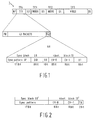
- Figure 1 shows the format of the signals as they are recorded in a track on a magnetic record carrier by means of a helical scan videorecorder.
- the left end of the track 1 in figure 1 is the start of the track and the right end of the track is the terminal part of the track.
- the track comprises a number of track parts.
- the track part denoted by G1 is the pre-amble track part, or clock run-in track part. It comprises as an example 47 25-bits pre-amble, or clock run-in, codewords.
- the clock run-in track part G1 has been described extensively in published European patent application 492,704 A1 (PHN 13,546).
- the application gives various possibilities for the bit patterns of the codewords to be used in the track part G1. As an example: a certain 25-bit long bit pattern and the inverse bit pattern of the said bit pattern can be used as codewords, where the choice for the bit pattern or the inverse bit pattern is determined by the tracking tone that is to be embedded in the track part G1.
- the track part G1 is followed by tracking tone recording part TP4, which is denoted by ITI (insert timing information) track part and which contains a tracking tone, synchronisation information and identification (or timing) information. Further explanation of the contents of the ITI track part will be given later.
- ITI insert timing information
- the track part TP4 is followed by an edit gap G2, which comprises as an example 37 25-bits codewords.
- the edit gap G2 is followed by the track part TP1, which is denoted by INDEX and which comprises amongst others subcode information, such as absolute and/or relative time information and a table of contents (TOC).
- This track part TP1 can comprise 45 25-bits words.
- the edit gap G3, which can comprise 52 25-bits codewords, is followed by a track part TP2 which comprises digital audio information included in 423 25-bits words.
- the edit gap G4 comprises in the present example 62 25-bits codewords, and is followed by a track part TP3 which comprises digital video information included in 4136 25-bits words.
- the track is terminated by the track part G5, which is the post-amble track part and comprises 47 25-bits codewords.
- the codewords used in the track part G5 can be the same codewords as the codewords used in the track part G1, where again the choice for a certain codeword or the inverse codeword depends on the tracking tone that is to be embedded in the track part G5.
- the ITI track part TP4 comprises in the present embodiment 43 packets P0, P1, ...., P42, of two 25-bits words each, resulting in 86 25-bits words in total.
- Figure 1 discloses the contents of a packet, such as packet P42.
- the packet comprises a 25-bit sync block SB and a 25-bit identification block ID.
- the sync block SB comprises a 17-bit sync pattern SP and an 8-bit dummy word D0.
- the identification block ID comprises a single bit SB, an 8-bit first binary count value CV-0, an 8-bit second binary count value CV-1 and an 8-bit dummy word D1.
- the following bit patterns for the various blocks are possible.
- the sync block SB can have different bit patterns called 'SB-A' and 'SB-B'.
- the 17-bit sync pattern SP has the bit pattern, 0000 1111 1111 1100 1, which has a disparity of +5.
- the corresponding dummy word D0 equals the pattern 0001 1001 and has a disparity of -2, so that the disparity of 'SB-A' in this case equals +3.
- the 17-bit sync pattern SP equals the bit pattern 1111 0000 0000 0011 0, which is the inverse of the sync pattern in 'SB-A', and consequently has a disparity of -5.
- the data pattern for the corresponding dummy word D0 is in this case 1110 0110, which is also the inverse of the previous data pattern for the dummy word.
- the disparity of this data pattern is +2, so that the disparity of "SB-B' equals -3.
- the 25-bit identification block can have two possible data patterns.
- the first data pattern called 'ID-A'
- the single bit SB equals '1'
- the 8-bit dummy word D1 equals 0111 1100.
- the 8-bit count value CV-0 has as the first two bits a '00' pattern, and the next 6 bits indicate the sequence number of the packet in which the identification block is included. That means that the CV-0 word in the packet P0 equals 0000 0000, and that the CV-0 word in the packet P42 equals 0010 1010.
- the relation holds that the CV-1 word is the inverse of the CV-0 word. Consequently, the disparity of 'ID-A' is +3.
- the most significant bit of the count values are written first. This lowers the energy of the count values, so that the energy near the tracking frequencies as a result of the presence of the count values is minimum.
- the SB bit is '0' and the 8-bit dummy word D1 equals 1000 0011.
- the 8-bit count value CV-0 has as the first two bits a '11' pattern, and the next 6 bits again indicate the sequence number of the packet in which the identification block is included. That means that the CV-0 word in the packet P0 equals 1100 0000, and that the CV-0 word in the packet P42 equals 1110 1010.
- the CV-1 word is again the inverse of the CV-0 word. Consequently, the disparity of the 'ID-B' is -3.
- the ITI track part could be obtained by concatenating blocks as follows: 'SB-A', 'ID-B', 'SB-A', 'ID-B', which sequence is repeated.
- a tracking frequency f0 which equals the frequency of the waveform of the running digital sum (or digital sum value) of all the disparities, having a certain value, as an example 360 kHz.
- the ITI track part could be obtained by concatenating as follows: 'SB-A', 'ID-A', 'SB-B', 'ID-B', which sequence is repeated.
- the ITI track part could be obtained by concatenating as follows: 'SB-A', 'ID-A', 'SB-A', 'ID-B', 'SB-B', 'ID-B', which sequence is repeated. This means that subsequent disparities appear: +3, +3, +3, -3, -3, -3 .... This results in a tracking frequency f2 to be equal to one third the frequency (of 360 kHz) given above. That is a value of 120 kHz, in the above given example.
- the frequency values mentioned above are lower than the bit frequency in the serial datastream, which is 1/T, where T is the length in time of one bit in the serial datastream.
- This tracking system is based on the detection of the crosstalk of the tracking tones recorded in the directly neighbouring tracks.
- the previous tracking tone of 120 kHz can have the disadvantage that, especially in the case that the tracks have a relatively narrow width, the crosstalk of this 120 kHz tracking tone can be present over more than one neighbouring track, so that it negatively influences the tracking in tracks lying further away from the track having the 120 kHz tracking tone.
- Increasing the frequency of the tracking tone towards a frequency between 180 kHz and 360 kHz would significantly improve this situation, as higher frequencies results in a smaller spread-out of the crosstalk.
- the embedding of the tracking tones is also applied to the signals included in the audio blocks TP2 and video blocks TP3.
- This embedding of any tracking frequency in the data to be recorded that is: not only the frequencies of 120, 180 and 360 kHz, but also frequencies in between those values, is realized very easily by means of the 24-to-25 bit modulator described in the previously mentioned EP 492,704.
- the bit pattern in the ITI track part is optimised for the frequencies of 120, 180 and 360 kHz, using a fixed bit pattern, the choice for a tracking frequency in between 180 and 360 kHz requires an adaptation of the fixed bit pattern in the ITI track part.
- the packets in the track part TP4 could comprise the sync block and the identification block shown in figure 2.
- the packets now comprise a sync block SB', which now only comprises the 17-bit syncpattern SP, and a 18-bit identification block ID', which now comprises the CV-0 word, the CV-1 word and a 2-bit word TB.
- the packet in figure 2 which is denoted by P i -A, i indicating the sequence number of the packet in the track part TP4, can have a sync pattern in the form of 0000 1111 1111 1100 1.
- the CV-0 and CV-1 words are again as described above and the 2-bit word TB has a pattern of '01'. This means that the packet P i -A has a disparity of +5.
- the packet in figure 2 can also be denoted by P i -B.
- the sync pattern is in the form of 1111 0000 0000 0011 0, which is the inverse of the sync pattern in P i -A.
- the CV-0 and CV-1 words are again as described above and the 2-bit word TB has a pattern of '10'. This means that the packet P i -B has a disparity of -5.
- the packets In order to generate the data stream for the ITI track part of a track in which a tracking frequency lying in the frequency region between 180 kHz and 360 kHz should be embedded, the packets should be concatenated as follows: P1-A, P2-B, P3-A, P4-B, and so on. This means that subsequent disparities appear: +5, -5, +5, -5, +5, -5, and so on.
- the number of 35-bit packets should be 61, plus in addition 15 bits so as to come to a total number of 2150 bits, which is the same as 43 x 50 bits.
- This 15 bits can be exchanged with the track part G1 of that same track.
- this track part normally includes 47 25-bit codewords.
- a track part G1 can be obtained by concatenating 34 35-bit codewords, which results in 1190 bits in the track part G1.
- a track part G1 of 47 25-bit codewords results in 1175 bits, which means that the 15 bits of the ITI track part can be exchanged with the G1 track part so as to make 34 35-bit codewords in the G1 track part possible.
- Figure 3 schematically shows an embodiment of the arrangement.
- the arrangement comprises a first and a second input terminal 10 and 11 respectively, for receiving a digital audio signal and a digital video signal respectively.
- the digital audio signal is converted in the conversion means 14 in a way as described in European patent application 492,704 A1.
- the digital video signal is converted in the conversion means 16 in a way as also described in European patent application 492,704 A1.
- the order in which the blocks of audio- and video information are recorded in a track is however in the reverse order as described in the said patent application.
- the arrangement comprises an edit-gap signal generator 18, a tracking tone signal (or ITI signal) generator 20, an index generator 22 and a central processing unit 24.
- Outputs of the generators 18, 20 and 22, and of the conversion means 14 and 16 are each coupled to a corresponding terminal of a multi-position switch 26, an output terminal (f) of which is coupled to write heads 28 and 30, accommodated on a rotatable head drum 32.
- the central processing unit 24 is adapted to control and activate the generators 18, 20 and 22, the conversion means 14 and 16 and the switch 26.
- a control signal input 42 of the central processing unit 24 is coupled to an output of a detector 40, which is located at a stationary position near the circumference of the head drum 32, which detector 40 supplies pulses for each rotation of the head drum, the pulses being a measure for the time instants that the start point of a new track is written or is read.
- the central processing unit 24 At the start of the recording of a new track, like the track in figure 1, the central processing unit 24 generates a control signal for the edit gap generator 18, in response to a pulse applied to its input 42. Further, the unit 24 generates a control signal to the switch 26. Under the influence of this control signal, the switch positions itself in a position in which the terminals a and f are interconnected.
- the generator 18 generates the pre-amble or clock run-in codewords for recording in the G1 track part of the track.
- the unit 24 generates a control signal to the generator 20 and a control signal to the switch 26, such that it interconnects its terminals d and f.
- the generator 20 generates the sequence of packets, as described in figure 1 or 2, for recording in the trackpart TP4. An embodiment of the generator 20 will be described later with reference to figure 4.
- the central processing unit 24 generates a control signal to the edit-gap generator 18, and a control signal to the switch 26, which is again positioned in the position a-f.
- the generator 18 generates the edit gap signal described previously with reference to figure 1, for recording in the edit gap G2.
- the processing unit 24 generates a control signal to the INDEX generator 22, and a control signal to the switch, which is now positioned in the position e-f.
- the generator 22 generates the signal for recording in the track part TP1 of the track in figure 1.
- the processing unit 24 supplies a control signal to the edit-gap generator 18 and the switch 26, so that the switch is again positioned into the position a-f.
- the generator 18 generates the edit gap signal described previously with reference to figure 1, for recording in the edit gap G3. This is followed by the generation of a control signal which is supplied to the audio conversion means 14, and a control signal to the switch 26, which is controlled into the position b-f.
- the audio information can now be recorded so as to obtain the track part TP2 of the track.
- the processing unit 24 supplies a control signal to the edit-gap generator 18 and the switch 26, so that the switch is again positioned into the position a-f.
- the generator 18 generates the edit gap signal described previously with reference to figure 1, for recording in the edit gap G4. This is followed by the generation of a control signal which is supplied to the video conversion means 16, and a control signal to the switch 26, which is controlled into the position c-f.
- the video information can now be recorded so as to obtain the track part TP3 of the track.
- the processing unit 24 supplies a control signal to the edit-gap generator 18 and the switch 26, so that the switch is again positioned into the position a-f.
- the generator 18 generates the edit gap signal for recording as the post-amble track part G5.
- Figure 4 shows an embodiment of the generator 20 in more detail.
- the generator comprises a memory 50 in which the bit pattern of 'SB-A', described previously with reference to figure 1, is stored.
- 'SB-B' can be obtained by inverting all the bits of 'SB-A'.
- Figure 4 shows an additional memory 51 in which the bit pattern for 'SB-B' is stored.
- the 25-bit wide bit patterns of 'SB-A' and 'SB-B' are supplied to corresponding inputs of a selector 52.
- the selector 52 selects one of the two 25-bit sync blocks under the influence of a control signal applied to a control signal input 53, and supplies the selected 25-bit sync block to its output 54.
- the output 54 of the selector 52 is coupled to a first input of a combiner 79.
- the generator further comprises memories 55a and 55b, which supply the 3-bit bitpatterns '100' and '011' respectively, memories 56a and 56b, which supply 2-bit bitpatterns '11' and '00' respectively and a memory 58 which supplies the 8-bit dummy word D1.
- the two 3-bit data patterns supplied by the memories 55a and 55b are supplied to inputs of a selector 70a.
- the two 2-bit datapatterns supplied by the memories 56a and 56b are supplied to inputs of a selector 70b.
- the 8-bit dummy word from the memory 58 and the inverted dummy word are supplied to inputs of a selector 70c.
- the selectors Under the influence of a control signal generated by the sequence generator 88, which control signal is applied to the control signal inputs 74a, 74b and 74c of the selectors 70a, 70b and 70c respectively, the selectors select either the one or the other data patterns applied to their inputs and supply the selected data pattern to their outputs 76a, 76b and 76c respectively.
- the outputs of the selectors 70a, 70b and 70c are coupled to a combiner 78.
- the generator is further provided with a packet counter 60, which cyclically counts from zero (decimal) to 42 under the influence of packet pulses applied to a clock input 62. At its output a 6-bit count value is present.
- This 6-bit count value is the 6-bit count value corresponding to the decimal count value of the counter 60.
- the 6-bit binary count value is applied to an inverter 66, which supplies a 6-bit inverted value at its output.
- the output of the block counter 60 as well as the output of the inverter 68 is also supplied to a combiner 78.
- the combiner combines the bit patterns supplied to its inputs.
- the combined outputs of the selectors 70a, 70b, 70c, the counter 60 and the inverter 66 form the 25-bit wide bit pattern of the identification block ID.
- the combiner 78 supplies the 25-bit identification block ID-A to its output.
- the combiner 78 supplies the 25-bit identification block ID-B to its output.
- the combiner 78 supplies the 25-bit identification block to a second input of the combiner 79.
- the combiner 79 combines the two 25-bit blocks so as to generate the 50-bit datapatterns for the packets P0 to P42, so that they can be recorded in the track part TP4 after having been subjected to a parallel-to-serial conversion in the converter 80.
- the generator further comprises an input 81 (which is not shown in figure 3) for receiving the head pulses generated by the detector 40.
- the head pulses are applied to inputs of a track counter 82 and the packet counter 60.
- the track counter 82 supplies a first, a second or a third control signal at its output, in response to the occurrence of a head pulse applied to its input.
- the first control signal relates to the tracking tone having the highest frequency, indicated by f0.
- the second control signal relates to the next highest frequency, indicated by f1.
- the third control signal relates to the lowest frequency, indicated by f2.
- the control signals are applied to an input 90 of a sequence generator 88.
- a packet pulse generator 84 is provided, having an input 94 coupled to the control signal input 96 of the generator 20. Under the influence of the control signal applied to the input 94, the packet pulse generator 84 generates 43 pulses, one pulse for each packet P i in the track part TP4, which pulses are applied to the input 62 of the packet counter 60, as well as to an input 98 of the sequence generator 88.
- the packet counter 60 counts from zero to 42, and the corresponding binary values of the count values are applied to the output 64 so as to generate the 'ID-A' and the 'ID-B' for the packets P0 to P42.
- the sequence generator 88 supplies such control signals to the selectors 52 and 70a, 70b and 70c, that, when the first control signal (relating to f0) is applied to the sequence generator 88, the following sync blocks and ID blocks are concatenated so as to form the ITI track part: 'SB-A', 'ID-B', 'SB-A', 'ID-B', which sequence is repeated.
- the third control signal (relating to f2) is applied to the sequence generator 88, the following sync blocks and ID blocks are concatenated so as to form the ITI track part: 'SB-A', 'ID-A, 'SB-A', 'ID-B', 'SB-B', 'ID-B', which sequence is repeated.
- the track counter 82 In again the next track, the track counter 82 generates again the first control signal (relating to f0), so that the first mentioned concatenation is again generated. This continues, so that cyclically the tracking tone signals f0, f1 and f2 are embedded in the ITI track part of each time three neighbouring tracks.
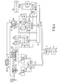
- Figure 5 shows an embodiment in which the f2 tone based on the concatenation of sync blocks and ID blocks as explained with reference to figure 2 can be generated.
- the generator disclosed in figure 5 includes a memory 110 in which the 17-bit sync pattern 0000 1111 1111 1100 1, followed by a 2-bit pattern '00' is stored. This 19-bit bitpattern is supplied to a first input of a selector 112 and, via an inverter 114, which inverts all the bits, to a second input of the selector 112.
- the functioning of the circuit part inside the broken lines indicated by reference numeral 116 is largely the same as in the corresponding circuit part in figure 4.
- the generator of figure 5 further comprises the memories 120a and 120b, for supplying the 2-bit word TB, which equals '01' and '10' for the packets P i -A and P i -B respectively.
- the outputs of the memories 120a and 120b are coupled to a selector 122.
- Outputs of the selectors 112, 70b and 122 and of the packet counter 60' and the inverter 68 are coupled to corresponding inputs of a combiner 124, which combines all the bits so as to obtain a 35-bit block for a packet P i.
- the 35-bit wide output signal of the combiner 124 is supplied to a parallel-serial converter 126, whose output is coupled to a first input 128 of a switch 130.
- FIG. 5 Also shown in figure 5 is the parallel-serial converter 80 of the circuit diagram of figure 4, whose output is now coupled to a second input 132 of the switch 130.
- the output 134 of the switch is coupled to the output 105 of the generator 20.
- a control signal input 136 of the switch 130 is further coupled to the output 86 of the track counter 82. Under the influence of the occurrence of the f2 control signal supplied by the track counter 82 to the switch 134, this switch connects the terminals 128 and 134 with each other, so that the 35-bit packets P i can be supplied to the output 105.
- the output 86 of the track counter 82 is also coupled to a control signal input 138 of the packet pulse generator 84', which under the influence of the control signal f2 supplies a sequence of 61 pulses to the packet counter 60', so as to obtain the 61 packets for the track having the f2 tracking tone embedded in it.
- the switch In the absence of the control signal f2, the switch is positioned in the other position, and connects the terminals 132 and 134 with each other, so that the packets generated by the circuit part of figure 4 can be supplied to the output 105. Further, in the absence of the control signal f2, the packet pulse generator 84' supplies only 43 packet pulses, as described previously in figure 4, so as to obtain the 43 packets in the other tracks.
- sync blocks having either the first or the second disparity such as +3 and -3, as in the previous example.
- the sync blocks can have more than two disparities.
- three disparities such as +2, 0 and -2, as an example.
- four disparities such as -3, -1, 1 and 3 as an example.
- identification blocks having either the third or fourth disparity. If required, the identification blocks can have more than two disparities.
- the sync blocks and the identification blocks in the subsequent packets are chosen with such a disparity that the running digital sum of the tracking tone signal varies as the relatively low frequency waveform described previously.
- first and second binary count value need not be accommodated serially after each other in the identification blocks.
- the count value and its inverted value are, in combination, DC free and result in little energy at the tracking tone frequencies.
- bits of the first binary count value CV-O to be b0, b1, ... b7, and the bits of the second binary count value b ⁇ 0, b ⁇ 1, ... b ⁇ 7.
- the bit sequence for a DC-free bit pattern in various ways such as: b0, ... b7, b ⁇ 0, ... b ⁇ 7 or b0...b3, b ⁇ 0... b ⁇ 3, b4...b7, b ⁇ 4... b ⁇ 7 or b0, b1, b ⁇ 0, b ⁇ 1, b2, b3, b ⁇ 2, b ⁇ 3, ... or b0, b ⁇ 0, b1, b ⁇ 1, b2, b ⁇ 2, ... b7, b ⁇ 7.
Priority Applications (1)
| Application Number | Priority Date | Filing Date | Title |
|---|---|---|---|
| EP94200152A EP0608946A3 (en) | 1993-01-28 | 1994-01-21 | Arrangement for recording a video signal and a corresponding audio signal in slant tracks on a longitudinal magnetic record carrier, and record carrier obtained by means of the arrangement. |
Applications Claiming Priority (5)
| Application Number | Priority Date | Filing Date | Title |
|---|---|---|---|
| EP93200215 | 1993-01-28 | ||
| EP93200215 | 1993-01-28 | ||
| EP93201263 | 1993-05-04 | ||
| EP93201263 | 1993-05-04 | ||
| EP94200152A EP0608946A3 (en) | 1993-01-28 | 1994-01-21 | Arrangement for recording a video signal and a corresponding audio signal in slant tracks on a longitudinal magnetic record carrier, and record carrier obtained by means of the arrangement. |
Publications (2)
| Publication Number | Publication Date |
|---|---|
| EP0608946A2 true EP0608946A2 (de) | 1994-08-03 |
| EP0608946A3 EP0608946A3 (en) | 1995-08-16 |
Family
ID=27235274
Family Applications (1)
| Application Number | Title | Priority Date | Filing Date |
|---|---|---|---|
| EP94200152A Withdrawn EP0608946A3 (en) | 1993-01-28 | 1994-01-21 | Arrangement for recording a video signal and a corresponding audio signal in slant tracks on a longitudinal magnetic record carrier, and record carrier obtained by means of the arrangement. |
Country Status (1)
| Country | Link |
|---|---|
| EP (1) | EP0608946A3 (de) |
Cited By (2)
| Publication number | Priority date | Publication date | Assignee | Title |
|---|---|---|---|---|
| US5579183A (en) * | 1994-04-08 | 1996-11-26 | U.S. Philips Corporation | Recording and reproducing an MPEG information signal on/from a record carrier |
| GB2361093A (en) * | 2000-04-05 | 2001-10-10 | Sony Uk Ltd | Digital video tape recording with metadata on slant tracks |
Citations (6)
| Publication number | Priority date | Publication date | Assignee | Title |
|---|---|---|---|---|
| EP0250049A1 (de) * | 1986-06-20 | 1987-12-23 | Koninklijke Philips Electronics N.V. | Kanalkodierer |
| EP0339724A1 (de) * | 1988-04-26 | 1989-11-02 | Koninklijke Philips Electronics N.V. | Anordnung zum Aufzeichnen eines digitalen Informationssignals |
| EP0436991A1 (de) * | 1990-01-08 | 1991-07-17 | Koninklijke Philips Electronics N.V. | Digitales Übertragungssystem und bei diesem Übertragungssystem benutzter Sender und Empfänger und Aufzeichnungsträger, der mittels des Senders in Form einer Aufzeichnungseinrichtung erhalten wird |
| EP0470792A1 (de) * | 1990-08-06 | 1992-02-12 | Matsushita Electric Industrial Co., Ltd. | Verfahren zur Aufzeichnung digitaler Signale |
| EP0473412A1 (de) * | 1990-08-31 | 1992-03-04 | Matsushita Electric Industrial Co., Ltd. | Verfahren zur Aufzeichnung digitaler Signale |
| EP0492704A1 (de) * | 1990-12-21 | 1992-07-01 | Koninklijke Philips Electronics N.V. | Anordnung zum Aufzeichnen von Takteinlauf-Codewörtern in einer Spur auf einem magnetischen Aufzeichnungsträger |
-
1994
- 1994-01-21 EP EP94200152A patent/EP0608946A3/en not_active Withdrawn
Patent Citations (6)
| Publication number | Priority date | Publication date | Assignee | Title |
|---|---|---|---|---|
| EP0250049A1 (de) * | 1986-06-20 | 1987-12-23 | Koninklijke Philips Electronics N.V. | Kanalkodierer |
| EP0339724A1 (de) * | 1988-04-26 | 1989-11-02 | Koninklijke Philips Electronics N.V. | Anordnung zum Aufzeichnen eines digitalen Informationssignals |
| EP0436991A1 (de) * | 1990-01-08 | 1991-07-17 | Koninklijke Philips Electronics N.V. | Digitales Übertragungssystem und bei diesem Übertragungssystem benutzter Sender und Empfänger und Aufzeichnungsträger, der mittels des Senders in Form einer Aufzeichnungseinrichtung erhalten wird |
| EP0470792A1 (de) * | 1990-08-06 | 1992-02-12 | Matsushita Electric Industrial Co., Ltd. | Verfahren zur Aufzeichnung digitaler Signale |
| EP0473412A1 (de) * | 1990-08-31 | 1992-03-04 | Matsushita Electric Industrial Co., Ltd. | Verfahren zur Aufzeichnung digitaler Signale |
| EP0492704A1 (de) * | 1990-12-21 | 1992-07-01 | Koninklijke Philips Electronics N.V. | Anordnung zum Aufzeichnen von Takteinlauf-Codewörtern in einer Spur auf einem magnetischen Aufzeichnungsträger |
Cited By (4)
| Publication number | Priority date | Publication date | Assignee | Title |
|---|---|---|---|---|
| US5579183A (en) * | 1994-04-08 | 1996-11-26 | U.S. Philips Corporation | Recording and reproducing an MPEG information signal on/from a record carrier |
| US5596581A (en) * | 1994-04-08 | 1997-01-21 | Philips Electronics North America Corporation | Recording and reproducing an MPEG information signal using tagged timing information |
| US6081526A (en) * | 1994-04-08 | 2000-06-27 | Saeijs; Ronald W. J. J. | Apparatus and methods for transmitting an MPEG information signal, and a method for reproducing that signal |
| GB2361093A (en) * | 2000-04-05 | 2001-10-10 | Sony Uk Ltd | Digital video tape recording with metadata on slant tracks |
Also Published As
| Publication number | Publication date |
|---|---|
| EP0608946A3 (en) | 1995-08-16 |
Similar Documents
| Publication | Publication Date | Title |
|---|---|---|
| US5400187A (en) | Arrangement for recording a video signal and a corresponding audio signal in slant tracks on a longitudinal magnetic record carrier, and record carrier obtained by means of the arrangement | |
| KR100221903B1 (ko) | 디지탈 정보 신호 기록 장치 | |
| RU2156039C2 (ru) | Устройство для записи цифрового сигнала | |
| US5365232A (en) | Data conversion method, pilot signal formation method using the same and rotary magnetic head device for use therein | |
| SE451775B (sv) | Tidbaskorrigeringsanordning for korrigering av tidbasfel | |
| KR850006958A (ko) | 로터리 헤드 방식의 pcm 기록 및 재생 방법과 그 시스템 | |
| EP0310330B1 (de) | Vorrichtung zum Aufnehmen und Wiedergeben von digitalen Signalen | |
| US4866544A (en) | Data modulation and demodulation system for magnetic recording system | |
| US4310860A (en) | Method and apparatus for recording data on and reading data from magnetic storages | |
| NL8104006A (nl) | Werkwijze en inrichting voor het redigeren van een op een registratiemedium opgenomen, digitaal signaal. | |
| US5446597A (en) | Apparatus for recording digital signals with associated auxiliary data | |
| EP0395125B1 (de) | PCM-Aufzeichnungs- und Wiedergabegerät | |
| EP0608946A2 (de) | Einrichtung zum Aufzeichnen eines Videosignals und eines entsprechenden Tonsignals in Schrägspuren auf einem longitudinalen magnetischen Aufzeichnungsträger und mittels der Einrichtung hergestellte Aufzeichnungsträger | |
| KR100251435B1 (ko) | 기록된 테입과 같은 자기 레코드 캐리어를 얻기 위한 장치 및 레코드 캐리어를 재생하기 위한 재생장치 | |
| KR0137377B1 (ko) | 정보신호 기록용 장치 | |
| US4132142A (en) | Method and apparatus for reproducing a musical presentation | |
| JP2947081B2 (ja) | デジタル情報変調装置 | |
| JPH11502356A (ja) | データ信号および追加の信号を記録キャリヤに記録し、再生する装置と、記録されたこのような信号を有する記録キャリヤ | |
| US5065260A (en) | Method for recording/reproducing expanded digital signals in conventional format | |
| US5644675A (en) | Method of helical scan magnetic tape recording | |
| US6317556B1 (en) | Sync block numbering of trick play signals during recording of such signals on a record carrier | |
| JPH07106976A (ja) | 符号変換方法、符号伝送装置及び磁気記録再生装置 | |
| US6288857B2 (en) | Digital signal recording apparatus, and related method | |
| JP3311428B2 (ja) | トラック追従制御方法 | |
| KR0151571B1 (ko) | 데이터기록방법 |
Legal Events
| Date | Code | Title | Description |
|---|---|---|---|
| PUAI | Public reference made under article 153(3) epc to a published international application that has entered the european phase |
Free format text: ORIGINAL CODE: 0009012 |
|
| AK | Designated contracting states |
Kind code of ref document: A2 Designated state(s): AT DE ES FR GB IT PT SE |
|
| RAP1 | Party data changed (applicant data changed or rights of an application transferred) |
Owner name: N.V. PHILIPS' GLOEILAMPENFABRIEKEN |
|
| PUAL | Search report despatched |
Free format text: ORIGINAL CODE: 0009013 |
|
| AK | Designated contracting states |
Kind code of ref document: A3 Designated state(s): AT DE ES FR GB IT PT SE |
|
| RAP1 | Party data changed (applicant data changed or rights of an application transferred) |
Owner name: N.V. PHILIPS' GLOEILAMPENFABRIEKEN |
|
| 17P | Request for examination filed |
Effective date: 19960216 |
|
| GRAG | Despatch of communication of intention to grant |
Free format text: ORIGINAL CODE: EPIDOS AGRA |
|
| 17Q | First examination report despatched |
Effective date: 19970808 |
|
| GRAG | Despatch of communication of intention to grant |
Free format text: ORIGINAL CODE: EPIDOS AGRA |
|
| GRAG | Despatch of communication of intention to grant |
Free format text: ORIGINAL CODE: EPIDOS AGRA |
|
| GRAH | Despatch of communication of intention to grant a patent |
Free format text: ORIGINAL CODE: EPIDOS IGRA |
|
| RAP3 | Party data changed (applicant data changed or rights of an application transferred) |
Owner name: KONINKLIJKE PHILIPS ELECTRONICS N.V. |
|
| STAA | Information on the status of an ep patent application or granted ep patent |
Free format text: STATUS: THE APPLICATION IS DEEMED TO BE WITHDRAWN |
|
| 18D | Application deemed to be withdrawn |
Effective date: 19980528 |