EP0608699B1 - Refrigerating apparatus - Google Patents
Refrigerating apparatus Download PDFInfo
- Publication number
- EP0608699B1 EP0608699B1 EP94100324A EP94100324A EP0608699B1 EP 0608699 B1 EP0608699 B1 EP 0608699B1 EP 94100324 A EP94100324 A EP 94100324A EP 94100324 A EP94100324 A EP 94100324A EP 0608699 B1 EP0608699 B1 EP 0608699B1
- Authority
- EP
- European Patent Office
- Prior art keywords
- refrigerating apparatus
- receptacle
- shell
- retaining elements
- webs
- Prior art date
- Legal status (The legal status is an assumption and is not a legal conclusion. Google has not performed a legal analysis and makes no representation as to the accuracy of the status listed.)
- Expired - Lifetime
Links
Images

Classifications
-
- F—MECHANICAL ENGINEERING; LIGHTING; HEATING; WEAPONS; BLASTING
- F25—REFRIGERATION OR COOLING; COMBINED HEATING AND REFRIGERATION SYSTEMS; HEAT PUMP SYSTEMS; MANUFACTURE OR STORAGE OF ICE; LIQUEFACTION SOLIDIFICATION OF GASES
- F25D—REFRIGERATORS; COLD ROOMS; ICE-BOXES; COOLING OR FREEZING APPARATUS NOT OTHERWISE PROVIDED FOR
- F25D23/00—General constructional features
- F25D23/06—Walls
- F25D23/062—Walls defining a cabinet
-
- F—MECHANICAL ENGINEERING; LIGHTING; HEATING; WEAPONS; BLASTING
- F25—REFRIGERATION OR COOLING; COMBINED HEATING AND REFRIGERATION SYSTEMS; HEAT PUMP SYSTEMS; MANUFACTURE OR STORAGE OF ICE; LIQUEFACTION SOLIDIFICATION OF GASES
- F25D—REFRIGERATORS; COLD ROOMS; ICE-BOXES; COOLING OR FREEZING APPARATUS NOT OTHERWISE PROVIDED FOR
- F25D25/00—Charging, supporting, and discharging the articles to be cooled
-
- F—MECHANICAL ENGINEERING; LIGHTING; HEATING; WEAPONS; BLASTING
- F25—REFRIGERATION OR COOLING; COMBINED HEATING AND REFRIGERATION SYSTEMS; HEAT PUMP SYSTEMS; MANUFACTURE OR STORAGE OF ICE; LIQUEFACTION SOLIDIFICATION OF GASES
- F25D—REFRIGERATORS; COLD ROOMS; ICE-BOXES; COOLING OR FREEZING APPARATUS NOT OTHERWISE PROVIDED FOR
- F25D2201/00—Insulation
- F25D2201/10—Insulation with respect to heat
- F25D2201/14—Insulation with respect to heat using subatmospheric pressure
Definitions
- the invention relates to a refrigerator, in particular a refrigerator and / or freezer, according to the preamble of the first claim.
- a gas-tight inner container is also located in a gas-tight outer housing, the free space between the outer housing and inner container being filled with an insulating material serving as a proppant.
- the outer housing and inner container are connected to one another in a gas-tight manner at their edge zones, so that the cavity filled with heat insulating material can also be evacuated.
- the inner walls of the inner container intended to hold goods to be cooled are smooth.
- Such a refrigerator with an integrated freezer compartment is also known from EP 0 071 090 A1.
- the invention has for its object to take measures in a refrigerator according to the preamble of the first claim, by which it is possible in a simple manner to accommodate built-in parts in the refrigerator.
- the holding elements are in particular arranged closely adjacent to wall surfaces of the container or the shell, so that they can be supported on them.
- the holding elements are designed as mutually parallel frames which rest against vertical walls of the container or the shell and which are supported on the lower horizontal floor surface or other wall parts projecting horizontally into the cooling space.
- the frames are preferably combined via horizontal connecting webs to form a cage, which can be placed in the inner container in particular without any aids.
- supports for storage plates or storage racks can be easily formed.
- retaining tabs, supports or guides for evaporator boards or evaporator grids can also be provided thereon.
- guides for shelves or evaporator grids or the like horizontally extending guide strips or guide grooves can be formed on horizontal webs be.
- fastening means for lighting elements and / or regulating or control elements are also provided on the holding elements.
- a fastening means for a lighting fixture is arranged on a connecting web between the frames. To hold the holding elements in a self-locking manner, they can be clamped under mechanical pretension between wall parts of the container or the shell. The frictional force thus generated then prevents these fasteners from automatically moving relative to the wall parts assigned to them.
- the frame or the cage can be made in one piece as a whole. To adapt to different inner container sizes, however, it is expedient to assemble these holding elements from individual parts.
- an additional intermediate frame can be provided between two frames if shortened supports or other built-in parts are to be used. It is expedient to hold the respective intermediate frame on connecting webs of the cage.
- a door 2, 4 is hinged to an outer housing 1, an inner container 3 with smooth walls being located in the outer housing 1 and an inner door shell 4 in the door 2, 4.
- a heat insulating material 5 which serves as a support means and which prevents the boundary walls from bending when the cavity is additionally evacuated.
- self-supporting holding elements 6 are inserted into the inner container 3 or in the inner door shell, which are located on the horizontal leg 7 of a rear molding or on the bottom 8 of the inner container and in the inner door shell support on the lower horizontal edge section and are made of plastic profiles (Fig. 1 and 2) or of wire. These parts 7, 8 absorb the weight forces of the holding elements 6 which may be loaded with installation elements.
- the container 3 like the inner door shell 4, but also the outer housing 1 and the outer door shell 2, is made of gas diffusion-tight, smooth metal sheet. In particular, 2.4 stainless steel is used for the inner container 3 as for the door.
- the holding elements 6 are in particular designed as a ladder-like frame 6.1, which stand up on the horizontal parts 7, 8 and likewise have plastic profiles or wire webs 6.2 (FIGS. 3 and 4) which are designed in the manner of rungs.
- the frames 6.1 lean closely against the rear wall 12 or the vertical side walls 10 of the inner container 3 or against the inner door shell 4.
- the horizontal webs 6.2 can serve as supports for storage plates or storage grids on which goods to be cooled can be placed.
- These webs 6.2 can be provided as guide strips or with guide grooves and, in accordance with FIGS. 3 and 4, are formed in pairs as guide strips in the manner of guide grooves into which these shelves can be inserted from the door.
- Evaporator boards or evaporator grids are also provided.
- At least one retaining tab 6.3 can also be provided on the rear spars of the frame 6.1, on which or between which an evaporator plate 11 can be fixed.
- the webs 6.2 can also carry pull-out refrigerated goods baskets in freezers.
- the holding elements are to represent a rigid structure in themselves, it is expedient to combine them into a prefabricated cage according to FIG. 1.
- This cage can be prefabricated in one piece or completely if a large number of identical elements is required in series production. Otherwise, it may be expedient to only produce the frames 6.1 in one piece with the webs 6.2 if only an adjustment in width is necessary (FIG. 2.5). Otherwise, the individual elements are made from individual parts, for example by plugging together, gluing or welding to match the internal dimensions of the inner container 3 or the inner door shell 4.
- the holding elements are designed as cages, the frames 6.1 are held together via connecting webs 6.4. It is sufficient if in particular the rear spars of the frames are connected to these connecting webs 6.4.
- the upper or lower end of the vertical spars facing the door 2.4 can also be connected to such a connecting web 6.4 without making it more difficult to access the inner container 3. Given the small depth of the inner door shell 4, it is sufficient if the spars adjacent to it are held together with a connecting web 6.4.
- the connecting webs 6.4 can additionally be provided with elements 6.5, which can in particular be a housing for interior lighting. If the holding element is attached to the front upper connecting web 6.4, it can Display elements or control means are provided. It is also expedient to arrange a controller and / or lighting combination between two horizontal, sufficiently spaced webs 6.2.
- the webs 6.2 are bow-shaped or bridge-shaped and protrude into the interior of the inner container 3. 3 and 4 form guide groove replicas into which storage plates or grids and the like can be inserted with their edges.
- the holding elements 6, in particular the frame 6.1 or the cage formed therefrom, can be matched to the inner dimensions of the inner container 3 or the inner door shell 4 in such a way that they are clamped under mechanical prestress between adjacent wall parts and are thus held by frictional engagement.
- an intermediate frame between two frames 6.1, which then rest in particular on side walls 10 of the container 3 or the shell 4.
- This intermediate frame can correspond wholly or partially to the frame 6.1 and serve for the storage of shelves or grids and the like, which do not extend across the entire width of the inner container 3, that is to say not from one outer frame 6.1 to the other outer frame 6.1.
- This or several of these intermediate frames are held on connecting webs 6.4, so that no additional parts are required for this either.
- the self-supporting holding elements 6 designed as plastic profile bars or wire gratings provide a possibility of being able to hold the installation parts required within a cooling space without having to carry out any damage or deformation of the walls in question. It is also possible to use a holding element for fastening a drip channel 6.7, which is below the evaporator 11 and collects condensation water dripping from the latter. This drip gutter 6.7 can also be detachably attached to the frame or a holding element or the evaporator 11.
Description
Die Erfindung betrifft ein Kältegerät, insbesondere ein Kühl- und/oder Gefriergerät, gemäß dem Oberbegriff des ersten Anspruchs.The invention relates to a refrigerator, in particular a refrigerator and / or freezer, according to the preamble of the first claim.
Bei einem bekannten Kühlgerät dieser Art (US-PS 2,795,020) befindet sich in einem gasdichten Außengehäuse ein ebenfalls gasdicht ausgebildeter Innenbehälter, wobei der freie Raum zwischen Außengehäuse und Innenbehälter mit einem als Stützmittel dienenden Isolierstoff ausgefüllt ist. Außengehäuse und Innenbehälter sind an ihren Randzonen gasdicht miteinander verbunden, so daß der mit Wärmeisolierstoff gefüllte Hohlraum zusätzlich evakuiert werden kann. Die Innenwände des für die Aufnahme von zu kühlendem Gut bestimmten Innenbehälters sind glatt ausgebildet. Ein derartiges Kühlgerät mit integriertem Gefrierfach ist auch aus der EP 0 071 090 A1 bekannt.In a known cooling device of this type (US Pat. No. 2,795,020), a gas-tight inner container is also located in a gas-tight outer housing, the free space between the outer housing and inner container being filled with an insulating material serving as a proppant. The outer housing and inner container are connected to one another in a gas-tight manner at their edge zones, so that the cavity filled with heat insulating material can also be evacuated. The inner walls of the inner container intended to hold goods to be cooled are smooth. Such a refrigerator with an integrated freezer compartment is also known from EP 0 071 090 A1.
Weiter ist aus der britischen Patentanmeldung Nr. 2 129 114 bekannt, eine Kohltruhe in einer Weise auszugestalten, daß bei übereinander gelagertem Kühlgut das in den unteren Lagen eingelagerte Gefriergut gut sichtbare ist. Hierzu ist in die Gefriertruhe ein Traggestell als Korbhalterung eingestellt, an dem die einzelnen Gefrierkörbe waagrecht verschiebbar gehalten sind. Ein vergleichbares Traggestell ist aus dem französischem Patent Nr. 1.050.538 bekannt, welches in eine tragbare Kühlbox einsetzbar und auch komplett mit dem zu kühlenden Gut herausnehmbar ist.Furthermore, it is known from British Patent Application No. 2 129 114 to design a cabbage chest in such a way that the frozen goods stored in the lower layers are clearly visible when the refrigerated goods are stacked on top of one another. For this purpose, a support frame is placed in the freezer as a basket holder, on which the individual freezer baskets are held horizontally displaceable. A comparable support frame is known from French Patent No. 1,050,538, which can be inserted into a portable cool box and can also be completely removed with the goods to be cooled.
Der Erfindung liegt die Aufgabe zugrunde, bei einem Kältegerät gemäß dem Oberbegriff des ersten Anspruchs Maßnahmen zu treffen, durch welche es auf einfache Weise möglich wird, Einbauteile im Kühlraum unterzubringen.The invention has for its object to take measures in a refrigerator according to the preamble of the first claim, by which it is possible in a simple manner to accommodate built-in parts in the refrigerator.
Die Lösung dieser Aufgabe erfolgt bei einem Kältegerät der eingangs genannten Art erfindungsgemäß durch die kennzeichnenden Merkmale des ersten Anspruchs. Bei einer Ausgestaltung eines Kältegeräts gemäß der Erfindung übernehmen selbsttragende Halteelemente die Funktion zur Ablagerung von Auflageplatten oder Rosten oder zur Befestigung von Beleuchtungs- oder Regel-bzw. Steuerelementen und dergl. Zusatzteilen. Auch Verdampfer oder Verdampferroste werden von solchen Halteelementen getragen. Dabei ist es möglich, die Halteelemente zugleich mit waagerechten Führungen zu versehen, um Kühlgutkörbe oder Ablagen verschiebbar darin zu halten. In entsprechender Weise läßt sich auch eine Türinnenschale mit solchen Halteelementen ausstatten, um beispielsweise Eierhalter, Butter- oder Käsefächer oder dergl. Ablagen daran festsetzen zu können. Da sich die Halteelemente auf waagerechten Partien des Behälters bzw. der Schale abstützen, bedarf es keiner besonderen Befestigungsmittel. Durchbrechungen oder besondere Verformungen der Behälterwände bzw. der Schale sind daher nicht erforderlich. Die Halteelemente sind insbesondere eng benachbart an Wandflächen des Behälters bzw. der Schale angeordnet, so daß sie sich daran abstützen können. Insbesondere sind die Halteelemente als sich parallel gegenüberstehende Rahmen ausgebildet, die an senkrechten Wänden des Behälters bzw. der Schale anliegen und die sich auf der unteren waagerechten Bodenfläche oder anderen waagerecht in den Kühlraum hineinstehenden Wandpartien abstützen. Dabei sind die Rahmen vorzugsweise über waagerechte Verbindungsstege zu einem Käfig zusammengefaßt, der ohne Hilfsmittel insbesondere im Innenbehälter stehen kann. Bei der Ausbildung der Halteelemente als Käfig brauchen die seitlichen Rahmen nicht an Seitenwänden des Innenbehälters anliegen, wenn der Rahmen in sich steif ist. An den Rahmen lassen sich in einfacher Weise Auflagen für Ablageplatten oder Ablageroste ausbilden. Es können jedoch auch Haltelaschen, Auflagen oder Führungen für Verdampferplatinen oder Verdampferroste daran vorgesehen sein. Als Führungen für Ablagen bzw. Verdampferroste oder dergl. können an waagrechten Stegen der Rahmen waagrecht verlaufende Führungsleisten oder Führungsnuten ausgebildet sein. An den Halteelementen werden jedoch auch Befestigungsmittel für Beleuchtungselemente und/oder Regel- bzw. Steuerelemente vorgesehen. Insbesondere wird ein Befestigungsmittel für einen Beleuchtungskörper an einem Verbindungssteg zwischen den Rahmen angeordnet. Zur selbstsichernden Halterung der Halteelemente können dieselben unter mechanischer Vorspannung zwischen Wandungsteile des Behälters bzw. der Schale eingespannt sein. Die dadurch erzeugte Reibungskraft verhindert dann eine selbsttätige Verschiebung dieser Befestigungsmittel gegenüber den ihnen zugeordneten Wandungsteilen. Die Rahmen bzw. der Käfig können als ganzes einstückig hergestellt sein. Zur Anpassung an unterschiedliche Innenbehältergrößen ist es jedoch zweckmäßig, diese Halteelemente aus Einzelteilen zusammenzusetzen. Im übrigen kann zwischen zwei Rahmen auch ein zusätzlicher Zwischenrahmen vorgesehen werden, wenn verkürzte Auflagen oder andere Einbauteile zur Anwendung gelangen sollen. Dabei ist es zweckmäßig, den jeweiligen Zwischenrahmen an Verbindungsstegen des Käfigs zu halten.This object is achieved according to the invention in a refrigeration device of the type mentioned at the outset by the characterizing features of the first claim. In a configuration of a refrigerator according to the invention, self-supporting holding elements take over Function for depositing support plates or grids or for fastening lighting or control or. Controls and the like. Additional parts. Evaporators or evaporator grids are also carried by such holding elements. It is possible to provide the holding elements with horizontal guides at the same time in order to slidably hold refrigerated goods baskets or shelves therein. In a corresponding manner, an inner door shell can also be equipped with such holding elements in order, for example, to be able to fix egg holders, butter or cheese compartments or the like. Since the holding elements are supported on horizontal parts of the container or the shell, no special fastening means are required. Breakthroughs or special deformations of the container walls or the shell are therefore not necessary. The holding elements are in particular arranged closely adjacent to wall surfaces of the container or the shell, so that they can be supported on them. In particular, the holding elements are designed as mutually parallel frames which rest against vertical walls of the container or the shell and which are supported on the lower horizontal floor surface or other wall parts projecting horizontally into the cooling space. The frames are preferably combined via horizontal connecting webs to form a cage, which can be placed in the inner container in particular without any aids. When the holding elements are in the form of a cage, the side frames do not need to rest against the side walls of the inner container if the frame is rigid in itself. On the frame, supports for storage plates or storage racks can be easily formed. However, retaining tabs, supports or guides for evaporator boards or evaporator grids can also be provided thereon. As guides for shelves or evaporator grids or the like, horizontally extending guide strips or guide grooves can be formed on horizontal webs be. However, fastening means for lighting elements and / or regulating or control elements are also provided on the holding elements. In particular, a fastening means for a lighting fixture is arranged on a connecting web between the frames. To hold the holding elements in a self-locking manner, they can be clamped under mechanical pretension between wall parts of the container or the shell. The frictional force thus generated then prevents these fasteners from automatically moving relative to the wall parts assigned to them. The frame or the cage can be made in one piece as a whole. To adapt to different inner container sizes, however, it is expedient to assemble these holding elements from individual parts. In addition, an additional intermediate frame can be provided between two frames if shortened supports or other built-in parts are to be used. It is expedient to hold the respective intermediate frame on connecting webs of the cage.
Die Erfindung ist nachfolgend anhand der Skizzen eines Ausführungsbeispiels näher erläutert.The invention is explained in more detail below with the aid of the sketches of an exemplary embodiment.
Es zeigen:
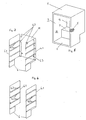
- Fig. 1 ein als Käfig ausgebildetes Halteelement und
- Fig. 2 einen perspektivischen Halbschnitt durch einen Kühl- oder Gefrierschrank mit eingesetzten Halteelementen.
- Fig. 3 ein als Draht-Käfig ausgebildetes weiteres Halteelement,
- Fig. 4 ein Paar von spiegelbildlich ausgebildeteten zusammengehörigen Halteelementen nach Fig. 3 und
- Fig. 5 eine perspektivische Ansicht eines Kühl- oder Gefrierschranks ohne Einbauteile.
- Fig. 1 is designed as a cage holding element and
- Fig. 2 is a perspective half section through a refrigerator or freezer with inserted holding elements.
- 3 shows a further holding element designed as a wire cage,
- Fig. 4 shows a pair of mirror-image associated holding elements according to Fig. 3 and
- Fig. 5 is a perspective view of a refrigerator or freezer without built-in parts.
Bei einem Kühlschrank ist an ein Außengehäuse 1 eine Tür 2,4 angelenkt, wobei sich im Außengehäuse 1 ein Innenbehälter 3 mit glatten Wänden und in der Tür 2,4 eine Türinnenschale 4 befindet. Im Hohlraum zwischen dem Außengehäuse 1 und dem Innenbehälter 3 bzw. in analoger Art zwischen der Türaußenschale 4 und der Türinnenschale befindet sich ein als Stützmittel dienender Wärmeisolierstoff 5, der ein Durchbiegen der Begrenzungswände verhindert, wenn der Hohlraum zusätzlich evakuiert wird.In the case of a refrigerator, a
Um im Innenbehälter 3 bzw. in der Türinnenschale Einbauteile festsetzen zu können, sind in den Innenbehälter 3 bzw. in die Türinnenschale selbsttragende Halteelemente 6 eingesetzt, die sich auf dem waagerechten Schenkel 7 einer rückwärtigen Einformung bzw. am Boden 8 des Innenbehälters und in der Türinnenschale an deren unteren waagerechten Randabschnitt abstützen und aus Kunststoffprofilen (Fig.1 und 2) oder aus Draht gefertigt sind. Diese Partien 7,8 nehmen die ggf. mit Einbauelementen belasteten Gewichtskräfte der Halteelemente 6 auf. Bei Anwendung einer evakuierten Vakuumisolation ist der Behälter 3 wie die Türinnenschale 4 aber auch das Außengehäuse 1 und die Türaußenschale 2 aus gasdiffusionsdichtem glattem Metallblech gefertigt. Insbesondere wird dabei für den Innenbehälter 3 wie für die Tür 2,4 Edelstahl verwendet. Die Halteelemente 6 sind insbesondere als leiterartig ausgebildete Rahmen 6.1 ausgebildet, die auf den waagerechten Partien 7,8 aufstehen und ebenfalls Kunststoffprofilen oder aus Draht (Fig. 3 und 4) bestehende, nach Art von Sprossen ausgebildete waagrechte Stege 6.2 besitzen. Die Rahmen 6.1 lehnen sich eng an die Rückwand 12 bzw. die senkrechten Seitenwände 10 des Innenbehälters 3 bzw. an der Türinnenschale 4 an. Die waagerechten Stege 6.2 können als Auflagen für Ablageplatten oder Ablageroste dienen, auf welche zu kühlendes Gut aufgestellt werden kann. Diese Stege 6.2 können als Führungsleisten oder mit Führungsnuten versehen sein und sind gemäß Fig. 3 und 4 paarig als Führungsleisten nach Art von Führungsnuten ausgebildet, in welche diese Ablagen von der Tür her einschiebbar sind. Als Ablagen werden dabei auch Verdampferplatinen oder Verdampferroste vorgesehen. Für einen Plattenverdampfer kann außerdem an rückwärtigen Holmen des Rahmens 6.1 wenigstens eine Haltelasche 6.3 vorgesehen werden, an welcher bzw. zwischen welchen eine Verdampferplatine 11 festgesetzt werden kann. Die Stege 6.2 können dabei aber auch in Gefrierschränken herausziehbare Kühlgutkörbe tragen.In order to be able to fix built-in parts in the
Wenn die Halteelemente ein in sich steifes Gebilde darstellen sollen, ist es zweckmäßig, sie zu einem vorgefertigten Käfig gemäß Fig. 1 zusammenzufassen. Dieser Käfig kann einstückig bzw. komplett vorgefertigt werden, wenn in einer Serienfertigung eine Vielzahl gleicher Elemente erforderlich ist. Anderenfalls kann es zweckmäßig sein, nur die Rahmen 6.1 mit den Stegen 6.2 einstückig herzustellen, wenn lediglich eine Anpassung in der Breite notwendig ist (Fig.2,5). Anderenfalls werden die einzelnen Elemente aus Einzelteilen, beispielsweise durch Zusammenstecken, Kleben oder Schweißen in Anpassung an die Innenabmessungen des Innenbehälters 3 bzw. der Türinnenschale 4 gefertigt. Bei der Ausbildung der Halteelemente als Käfig werden die Rahmen 6.1 über Verbindungsstege 6.4 zusammengehalten. Dabei genügt es, wenn insbesondere die rückwärtigen Holme der Rahmen mit diesen Verbindungsstegen 6.4 verbunden werden. Es kann auch das obere bzw. untere Ende der der Tür 2.4 zugewandten senkrechten Holme mit einem solchen Verbindungssteg 6.4 verbunden werden, ohne die Zugriffmöglichkeit in den Innenbehälter 3 zu erschweren. Bei der geringen Tiefe der Türinnenschale 4 genügt es, wenn die derselben benachbarten Holme mit einem Verbindungssteg 6.4 zusammengehalten sind. Dabei können die Verbindungsstege 6.4 zusätzlich mit Elementen 6.5 versehen sein, wobei es sich dabei insbesondere um ein Gehäuse für eine Innenbeleuchtung handeln kann. Wird das Halteelement am vorderen oberen Verbindungssteg 6.4 angebracht, können daran Anzeigeelemente oder Steuermittel vorgesehen werden. Zweckmäßig ist es auch, eine Regler- und/oder Beleuchtungskombination zwischen zwei waagerechten, ausreichend beabstandeten Stegen 6.2 anzuordnen. Die Stege 6.2 sind bügel- oder brückenförmig ausgebildet und ragen in das Innere des Innenbehälters 3 hinein. Dabei bilden eng benachbart übereinander angeordnete Drahtstege 6.2 nach Fig. 3 und 4 Führungsnuten-Nachbildungen, in die Ablageplatten oder Roste und dergl. mit ihren Rändern einschiebbar sind.If the holding elements are to represent a rigid structure in themselves, it is expedient to combine them into a prefabricated cage according to FIG. 1. This cage can be prefabricated in one piece or completely if a large number of identical elements is required in series production. Otherwise, it may be expedient to only produce the frames 6.1 in one piece with the webs 6.2 if only an adjustment in width is necessary (FIG. 2.5). Otherwise, the individual elements are made from individual parts, for example by plugging together, gluing or welding to match the internal dimensions of the
Die Halteelemente 6, insbesondere die Rahmen 6.1 bzw. der daraus gebildete Käfig kann so auf das Innenmaß des Innenbehälters 3 bzw. der Türinnenschale 4 abgestimmt sein, daß sie unter mechanischer Vorspannung zwischen benachbarten Wandungsteilen eingespannt sind und so durch Reibschluß gehalten werden. Daneben ist noch möglich, zwischen zwei Rahmen 6.1, die dann insbesondere an Seitenwänden 10 des Behälters 3 bzw. der Schale 4 anliegen, einen Zwischenrahmen anzuordnen. Dieser Zwischenrahmen kann ganz oder teilweise den Rahmen 6.1 entsprechen und für die Auflagerung von Ablagen oder Rosten und dergl. dienen, die nicht über die gesamte Breite des Innenbehälters 3, also nicht von einem äußeren Rahmen 6.1 zum anderen äußeren Rahmen 6.1 reichen. Dabei wird dieser oder auch mehrere dieser Zwischenrahmen an Verbindungsstegen 6.4 gehalten, so daß auch dafür keine Zusatzteile erforderlich sind. Insgesamt ergibt sich so durch die selbsttragenden als Kunststoffprofilstäbe oder Drahtroste ausgebildeten Halteelemente 6 eine Möglichkeit, die innerhalb eines Kühlraumes erforderlichen Einbauteile halten zu können, ohne eine Beschädigung oder Verformung der betreffenden Wandungen vornehmen zu müssen. Dabei ist es auch möglich, ein Halteelement für die Befestigung einer Tropfrinne 6.7 auszunutzen, die unterhalb des Verdampfers 11 liegt und von letzterem abtropfendes Tauwasser auffängt. Diese Tropfrinne 6.7 kann auch ggf. lösbar an den Rahmen bzw. ein Halteelement oder den Verdampfer 11 angesetzt werden.The holding
Claims (17)
- A refrigerating apparatus, more particularly a refrigerator and/or freezer, with vacuum insulation and smooth walls of the inner receptacle (3) and/or of the door inner shell (4), the walls being made of gas diffusion-proof metal sheets, characterised in that self-supporting retaining elements (6) supported on horizontal parts of the inner receptacle (3) are constructed in such a manner that components provided in the device, at least one depositing grille or plate, an evaporating element, a light unit, a regulating and/or control element, a door shelf, can be arranged on the retaining elements (6).
- A refrigerating apparatus according to claim 1, characterised in that the receptacle (3) or the shell (4) is made of high-grade steel.
- A refrigerating apparatus according to claim 1 or 2, characterised in that the retaining elements (6) are arranged closely adjacent one another on wall surfaces of the receptacle (3) or the shell (4).
- A refrigerating apparatus according to claim 1 or one of the following, characterised in that the retaining elements (6) are constructed as frames (6.1), which are arranged parallel and opposite one another and rest against vertical walls (10) of the receptacle (3) or the shell (4).
- A refrigerating apparatus according to claim 4, characterised in that the frames (6.1) are joined together via connecting webs (6.4) to form a cage.
- A refrigerating apparatus according to claim 5, characterised in that the connecting webs (6.4) are provided with retaining elements (6.5).
- A refrigerating apparatus according to claim 1 or one of the following, characterised in that the retaining elements (6.2) comprise horizontally extending guide strips or grooves over the depth of the receptacle (3) or the shell (4) for chilled goods baskets or shelves.
- A refrigerating apparatus according to one of claims 5 to 7, characterised in that securing means (6.5) are arranged on at least one connecting web (6.4).
- A refrigerating apparatus according to one of claims 4 to 8, characterised in that retaining elements (6) are clamped with mechanical prestressing between wall parts of the receptacle (3) and/or the shell (4).
- A refrigerating apparatus according to claim 4 or one of the following, characterised in that the frame (6.1) or the cage is integrally formed.
- A refrigerating apparatus according to one of claims 4 to 9, characterised in that the frame (3) or the cage is composed of individual parts.
- A refrigerating apparatus according to claim 4 or one of the following, characterised in that an intermediate frame is arranged between two frames resting against lateral walls (10) of the receptacle (3) or the shell (4).
- A refrigerating apparatus according to claim 5, characterised in that the intermediate frame is held on connecting webs (6.4) of the cage.
- A refrigerating apparatus according to claim 1 or one of the following, characterised in that a retaining element provided beneath the evaporator (19) is constructed as a drip gutter (6.7) or supports a drip gutter (6.7).
- A refrigerating apparatus according to claim 1 or one of the following, characterised in that the retaining elements (6) are constructed in the manner of wire grilles.
- A refrigerating apparatus according to claim 15, characterised in that a retaining element (6) comprises a closed frame (6.1) made of wire, on which horizontal wire webs (6.2) constructed in the manner of rungs are fitted, which are bent in the manner of brackets and project into the interior of the refrigerating receptacle (3).
- A refrigerating apparatus according to claim 15 or 16, characterised in that wire webs (6.2) are arranged above one another and closely adjacent one another in pairs and form guides for chilled goods shelves, evaporator plates or grilles, which engage with peripheral areas between the wire webs (6.2) arranged in pairs.
Applications Claiming Priority (4)
| Application Number | Priority Date | Filing Date | Title |
|---|---|---|---|
| DE19934302332 DE4302332A1 (en) | 1993-01-28 | 1993-01-28 | Prefabricated rigid frame for interior components of refrigerator |
| DE4302332 | 1993-01-28 | ||
| DE4342892A DE4342892A1 (en) | 1993-01-28 | 1993-12-16 | Cooling unit |
| DE4342892 | 1993-12-16 |
Publications (3)
| Publication Number | Publication Date |
|---|---|
| EP0608699A2 EP0608699A2 (en) | 1994-08-03 |
| EP0608699A3 EP0608699A3 (en) | 1994-10-26 |
| EP0608699B1 true EP0608699B1 (en) | 1997-09-17 |
Family
ID=25922590
Family Applications (1)
| Application Number | Title | Priority Date | Filing Date |
|---|---|---|---|
| EP94100324A Expired - Lifetime EP0608699B1 (en) | 1993-01-28 | 1994-01-12 | Refrigerating apparatus |
Country Status (3)
| Country | Link |
|---|---|
| EP (1) | EP0608699B1 (en) |
| DE (2) | DE4342892A1 (en) |
| ES (1) | ES2107691T3 (en) |
Cited By (1)
| Publication number | Priority date | Publication date | Assignee | Title |
|---|---|---|---|---|
| DE102017119088A1 (en) | 2017-08-21 | 2019-02-21 | Liebherr-Hausgeräte Ochsenhausen GmbH | Fridge and / or freezer |
Families Citing this family (2)
| Publication number | Priority date | Publication date | Assignee | Title |
|---|---|---|---|---|
| ITVA20020011A1 (en) * | 2002-02-07 | 2003-08-07 | Whirlpool Co | DOMESTIC REFRIGERATOR AND PROCEDURE FOR ITS REALIZATION |
| DE102006061152A1 (en) * | 2006-12-22 | 2008-06-26 | BSH Bosch und Siemens Hausgeräte GmbH | The refrigerator |
Family Cites Families (9)
| Publication number | Priority date | Publication date | Assignee | Title |
|---|---|---|---|---|
| FR1050538A (en) * | 1954-01-08 | |||
| US2671004A (en) * | 1949-10-28 | 1954-03-02 | Perfection Stove Co | Rack guide for cooking ovens |
| US2795020A (en) * | 1952-12-30 | 1957-06-11 | Gen Electric | Methods of making insulated cabinets |
| DE1804747U (en) * | 1959-10-23 | 1960-01-28 | Carl Moehner | COOLING BOX. |
| US3083836A (en) * | 1962-02-01 | 1963-04-02 | Paul London | Freezer rack |
| SU937925A1 (en) * | 1980-01-04 | 1982-06-23 | Киевский Ордена Ленина Завод "Ленинская Кузница" | Freezing unit |
| IT1144387B (en) * | 1981-07-16 | 1986-10-29 | Indesit | INSULATION SYSTEM FOR A REFRIGERATOR |
| GB2129114B (en) * | 1982-10-20 | 1986-04-16 | Christopher Hugh Josep Simpson | Storage of goods in a cabinet |
| GB2192701A (en) * | 1986-05-07 | 1988-01-20 | Richard Craven & Co Ltd | Improvements in or relating to the displaying of goods for sale |
-
1993
- 1993-12-16 DE DE4342892A patent/DE4342892A1/en not_active Ceased
-
1994
- 1994-01-12 ES ES94100324T patent/ES2107691T3/en not_active Expired - Lifetime
- 1994-01-12 DE DE59404055T patent/DE59404055D1/en not_active Expired - Fee Related
- 1994-01-12 EP EP94100324A patent/EP0608699B1/en not_active Expired - Lifetime
Cited By (1)
| Publication number | Priority date | Publication date | Assignee | Title |
|---|---|---|---|---|
| DE102017119088A1 (en) | 2017-08-21 | 2019-02-21 | Liebherr-Hausgeräte Ochsenhausen GmbH | Fridge and / or freezer |
Also Published As
| Publication number | Publication date |
|---|---|
| EP0608699A3 (en) | 1994-10-26 |
| EP0608699A2 (en) | 1994-08-03 |
| DE59404055D1 (en) | 1997-10-23 |
| DE4342892A1 (en) | 1995-06-22 |
| ES2107691T3 (en) | 1997-12-01 |
Similar Documents
| Publication | Publication Date | Title |
|---|---|---|
| EP2414756B1 (en) | Household refrigerator | |
| EP1882146B1 (en) | Refrigerator comprising an extractably guided receptacle for chilled goods | |
| EP0675332B1 (en) | Refrigerator with shelves for goods to be cooled | |
| EP1032797B1 (en) | Refrigerating device | |
| DE102009002059B4 (en) | Refrigerating appliance, in particular household refrigerating appliance, and storage arrangement therefor | |
| EP3549489B1 (en) | Chamber for cooling or heating goods | |
| EP2816304A1 (en) | Cooling device with holders for a shelf | |
| EP0608699B1 (en) | Refrigerating apparatus | |
| DE3605891A1 (en) | Cooling device, in particular domestic refrigerator | |
| DE202006007152U1 (en) | Cool rack kit comprises four main modules, with base module consisting of insulated bottom tray in which are fitted heat exchanger and fan sub-assembly, and rear wall module with rear wall and air deflection wall | |
| EP1225404A2 (en) | Cabinet for storing wine | |
| DE202010008333U1 (en) | cooling rack kit | |
| EP1816418A2 (en) | Cooling device for storing bottles | |
| DE4436736A1 (en) | fridge | |
| DE3810212A1 (en) | FREEZER | |
| DE4420149A1 (en) | Refrigerator installation with integral construction refrigerant panels | |
| DE4302332A1 (en) | Prefabricated rigid frame for interior components of refrigerator | |
| EP0175248B1 (en) | Oven with hot air recirculation | |
| EP2218994A2 (en) | Cooler with pull-out storage boards and underlying storage compartments | |
| WO2012136537A2 (en) | Refrigerator arrangement having a refrigerating storage element | |
| DE3544873C1 (en) | Refrigerating appliance, in particular domestic refrigerator | |
| DE102009002443A1 (en) | Refrigerating appliance, in particular household refrigerating appliance | |
| DE102011077370A1 (en) | Storage arrangement for cooling device i.e. household cooling device, utilized for storing e.g. beverages in determined temperature, has cooling goods carriers suspended at front and rear edges of lower shelf over hook element | |
| DE10163187A1 (en) | The refrigerator | |
| DE102011077371A1 (en) | Tray assembly for refrigerator, particularly household refrigerator, has bottom refrigerated goods carrier, which has one connecting point, at which bottom refrigerated goods carrier is coupled with additional refrigerated goods carrier |
Legal Events
| Date | Code | Title | Description |
|---|---|---|---|
| PUAI | Public reference made under article 153(3) epc to a published international application that has entered the european phase |
Free format text: ORIGINAL CODE: 0009012 |
|
| AK | Designated contracting states |
Kind code of ref document: A2 Designated state(s): DE ES FR GB IT |
|
| PUAL | Search report despatched |
Free format text: ORIGINAL CODE: 0009013 |
|
| AK | Designated contracting states |
Kind code of ref document: A3 Designated state(s): DE ES FR GB IT |
|
| 17P | Request for examination filed |
Effective date: 19950308 |
|
| RAP1 | Party data changed (applicant data changed or rights of an application transferred) |
Owner name: AEG HAUSGERAETE GMBH |
|
| 17Q | First examination report despatched |
Effective date: 19951127 |
|
| GRAG | Despatch of communication of intention to grant |
Free format text: ORIGINAL CODE: EPIDOS AGRA |
|
| GRAH | Despatch of communication of intention to grant a patent |
Free format text: ORIGINAL CODE: EPIDOS IGRA |
|
| GRAH | Despatch of communication of intention to grant a patent |
Free format text: ORIGINAL CODE: EPIDOS IGRA |
|
| GRAA | (expected) grant |
Free format text: ORIGINAL CODE: 0009210 |
|
| AK | Designated contracting states |
Kind code of ref document: B1 Designated state(s): DE ES FR GB IT |
|
| PG25 | Lapsed in a contracting state [announced via postgrant information from national office to epo] |
Ref country code: FR Free format text: THE PATENT HAS BEEN ANNULLED BY A DECISION OF A NATIONAL AUTHORITY Effective date: 19970917 |
|
| ITF | It: translation for a ep patent filed |
Owner name: PROPRIA PROTEZIONE PROPR. IND. |
|
| REF | Corresponds to: |
Ref document number: 59404055 Country of ref document: DE Date of ref document: 19971023 |
|
| ET | Fr: translation filed | ||
| REG | Reference to a national code |
Ref country code: ES Ref legal event code: FG2A Ref document number: 2107691 Country of ref document: ES Kind code of ref document: T3 |
|
| GBT | Gb: translation of ep patent filed (gb section 77(6)(a)/1977) |
Effective date: 19971118 |
|
| PG25 | Lapsed in a contracting state [announced via postgrant information from national office to epo] |
Ref country code: GB Free format text: LAPSE BECAUSE OF NON-PAYMENT OF DUE FEES Effective date: 19980112 |
|
| PG25 | Lapsed in a contracting state [announced via postgrant information from national office to epo] |
Ref country code: ES Free format text: LAPSE BECAUSE OF NON-PAYMENT OF DUE FEES Effective date: 19980113 |
|
| PLBE | No opposition filed within time limit |
Free format text: ORIGINAL CODE: 0009261 |
|
| STAA | Information on the status of an ep patent application or granted ep patent |
Free format text: STATUS: NO OPPOSITION FILED WITHIN TIME LIMIT |
|
| GBPC | Gb: european patent ceased through non-payment of renewal fee |
Effective date: 19980112 |
|
| 26N | No opposition filed | ||
| REG | Reference to a national code |
Ref country code: FR Ref legal event code: ST |
|
| PGFP | Annual fee paid to national office [announced via postgrant information from national office to epo] |
Ref country code: DE Payment date: 19990212 Year of fee payment: 6 |
|
| PG25 | Lapsed in a contracting state [announced via postgrant information from national office to epo] |
Ref country code: DE Free format text: LAPSE BECAUSE OF NON-PAYMENT OF DUE FEES Effective date: 20001101 |
|
| REG | Reference to a national code |
Ref country code: ES Ref legal event code: FD2A Effective date: 20021016 |
|
| PG25 | Lapsed in a contracting state [announced via postgrant information from national office to epo] |
Ref country code: IT Free format text: LAPSE BECAUSE OF NON-PAYMENT OF DUE FEES;WARNING: LAPSES OF ITALIAN PATENTS WITH EFFECTIVE DATE BEFORE 2007 MAY HAVE OCCURRED AT ANY TIME BEFORE 2007. THE CORRECT EFFECTIVE DATE MAY BE DIFFERENT FROM THE ONE RECORDED. Effective date: 20050112 |