EP0608425A1 - Device for measuring viscosity of liquid - Google Patents
Device for measuring viscosity of liquid Download PDFInfo
- Publication number
- EP0608425A1 EP0608425A1 EP92921482A EP92921482A EP0608425A1 EP 0608425 A1 EP0608425 A1 EP 0608425A1 EP 92921482 A EP92921482 A EP 92921482A EP 92921482 A EP92921482 A EP 92921482A EP 0608425 A1 EP0608425 A1 EP 0608425A1
- Authority
- EP
- European Patent Office
- Prior art keywords
- viscosity
- pressure
- liquid sample
- time
- liquid
- Prior art date
- Legal status (The legal status is an assumption and is not a legal conclusion. Google has not performed a legal analysis and makes no representation as to the accuracy of the status listed.)
- Granted
Links
Images


Classifications
-
- G—PHYSICS
- G01—MEASURING; TESTING
- G01N—INVESTIGATING OR ANALYSING MATERIALS BY DETERMINING THEIR CHEMICAL OR PHYSICAL PROPERTIES
- G01N35/00—Automatic analysis not limited to methods or materials provided for in any single one of groups G01N1/00 - G01N33/00; Handling materials therefor
- G01N35/10—Devices for transferring samples or any liquids to, in, or from, the analysis apparatus, e.g. suction devices, injection devices
- G01N35/1081—Devices for transferring samples or any liquids to, in, or from, the analysis apparatus, e.g. suction devices, injection devices characterised by the means for relatively moving the transfer device and the containers in an horizontal plane
- G01N35/109—Devices for transferring samples or any liquids to, in, or from, the analysis apparatus, e.g. suction devices, injection devices characterised by the means for relatively moving the transfer device and the containers in an horizontal plane with two horizontal degrees of freedom
-
- G—PHYSICS
- G01—MEASURING; TESTING
- G01N—INVESTIGATING OR ANALYSING MATERIALS BY DETERMINING THEIR CHEMICAL OR PHYSICAL PROPERTIES
- G01N11/00—Investigating flow properties of materials, e.g. viscosity, plasticity; Analysing materials by determining flow properties
- G01N11/02—Investigating flow properties of materials, e.g. viscosity, plasticity; Analysing materials by determining flow properties by measuring flow of the material
- G01N11/04—Investigating flow properties of materials, e.g. viscosity, plasticity; Analysing materials by determining flow properties by measuring flow of the material through a restricted passage, e.g. tube, aperture
- G01N11/08—Investigating flow properties of materials, e.g. viscosity, plasticity; Analysing materials by determining flow properties by measuring flow of the material through a restricted passage, e.g. tube, aperture by measuring pressure required to produce a known flow
-
- G—PHYSICS
- G01—MEASURING; TESTING
- G01N—INVESTIGATING OR ANALYSING MATERIALS BY DETERMINING THEIR CHEMICAL OR PHYSICAL PROPERTIES
- G01N33/00—Investigating or analysing materials by specific methods not covered by groups G01N1/00 - G01N31/00
- G01N33/48—Biological material, e.g. blood, urine; Haemocytometers
- G01N33/483—Physical analysis of biological material
- G01N33/487—Physical analysis of biological material of liquid biological material
- G01N33/49—Blood
-
- G—PHYSICS
- G01—MEASURING; TESTING
- G01N—INVESTIGATING OR ANALYSING MATERIALS BY DETERMINING THEIR CHEMICAL OR PHYSICAL PROPERTIES
- G01N35/00—Automatic analysis not limited to methods or materials provided for in any single one of groups G01N1/00 - G01N33/00; Handling materials therefor
- G01N35/10—Devices for transferring samples or any liquids to, in, or from, the analysis apparatus, e.g. suction devices, injection devices
- G01N35/1009—Characterised by arrangements for controlling the aspiration or dispense of liquids
- G01N2035/1025—Fluid level sensing
Definitions
- the present invention relates to a liquid viscosity measuring device and more particularly to a liquid viscosity measuring device which enables a simultaneous measurement of a viscosity of a liquid sample with aspiration of the liquid sample in a pipetting apparatus or the like.
- a collected blood sample 10 is put into a test tube 12 and then separated into a blood plasma component 14 and a red blood cell component 16 by centrifugation. Practically, a small quantity of white blood cell component 18 appears between the blood plasma component 14 and the red blood cell component 16.
- a blood sample pipetting method which is carried out in a conventional pipetting apparatus generally comprises two processes, including a process of pipetting blood plasma and a process of pipetting red blood cells.
- the blood plasma component 14 is aspirated through a nozzle tip 20, and then dispensed into a plurality of other recipient containers 22 in a predetermined volume, respectively.
- the red blood cell pipetting process the red blood cell component 16 is aspirated through the nozzle tip 20, and then transferred to a diluting container (not shown) to be mixed with a diluent. Thereafter, the diluted red blood cell component 16 is aspirated again through the nozzle tip 20 and then dispensed into a plurality of other recipient containers 24, respectively in a predetermined volume.
- Blood type testing reagents i.e., a reagent for the blood plasma component and a reagent for the red blood cell component
- a reagent for the blood plasma component and a reagent for the red blood cell component are then introduced into the recipient containers 22, 24, respectively.
- these recipient containers 22, 24 are conveyed to an agglutination testing apparatus, where agglutination of the samples in the containers 22, 24 are measured optically.
- a type, B type, 0 type or AB type, or Rh type, or the like is determined.
- the viscosity of the red blood cell component is useful data for diagnosing diseases, and it is also a useful factor for determining an aspiration pressure to be set when pipetting the blood sample.
- a capillary viscometer As an apparatus for measuring the viscosity of the liquid sample, a capillary viscometer, a rotational viscometer, a falling body viscometer, an oscillational viscometer, and the like are conventionally well known. However, it takes a long time to measure the viscosity with these conventional viscometers, and their operations are troublesome. Further, these viscometers require to prepare a predetermined volume of the blood sample to be used for the viscosity measurement, in addition to the blood sample to be used for the pipetting. Therefore, when measuring the viscosity of the blood sample by the conventional viscometers, there is a disadvantage in that recycling of the blood sample used for the viscosity measurement is difficult.
- This invention has been made in view of above problems. It is therefore an object of the present invention to provide a liquid viscosity measuring device capable of measuring a viscosity of a liquid sample simultaneously with the aspiration of the liquid sample.
- Another object of the present invention is to provide a pipetting apparatus which enables simultaneous viscosity measurement during the pipetting operation, without preparing another blood sample to be used only for the viscosity measurement.
- a liquid viscosity measuring device comprising: a viscosity table storing data corresponding to relationship between a viscosity of a liquid sample and a time required from a point of time when the liquid sample is aspirated under a predetermined initial aspiration pressure to a point of time when the aspiration pressure of an aspiration system reaches a predetermined value; and a viscosity measuring unit for measuring the required time for the liquid sample, and comparing the required time with the data in said table, thereby obtaining the viscosity of the liquid sample.
- the aforementioned object can be also achieved by a pipetting apparatus having a liquid sample aspirating device including a nozzle tip for aspirating a liquid sample, an aspirating pump connected to the nozzle tip, and a pressure sensor for measuring a pressure in an aspiration system, wherein the pipetting apparatus further comprises a liquid viscosity measuring device as defined in Claim 1 which measures the viscosity of the liquid sample simultaneously with the aspiration of the liquid sample.
- a viscosity table representing the relationship between the required time and the viscosity of the liquid sample is previously prepared.
- the viscosity measuring unit measures the required time for the liquid sample to obtain the viscosity of the liquid sample with reference to the data stored in the viscosity table.
- the viscosity of the blood sample can be measured simultaneously with the pipetting operation of the blood sample. Further, it is possible to measure the viscosity, without preparing a predetermined volume of a blood sample to be used only for the viscosity measurement.
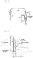
- FIG. 5 shows schematically a construction of an ordinary aspirating device used in a pipetting apparatus or the like.
- a nozzle chip 20 is connected to a pump 104 via an air hose 102.
- the pump 104 is composed of a cylinder 106 and a piston 108.
- the air hose 102 is equipped with a pressure sensor 110 for detecting an internal pressure of the air hose 102.
- Fig. 6 shows changes of the pressure in the aspiration system which are detected by the pressure sensor 110, after the initial aspiration pressure has been produced by pulling downwardly the piston 108 as shown in Fig.5.
- a predetermined pressure value is determined as ⁇
- the time required until a produced pressure reaches the predetermined value ⁇ differs depending on the viscosity of a liquid sample to be aspirated.
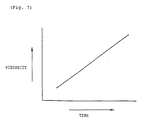
- Fig. 7 shows the relationship between the required time and the viscosity. The relationship therebetween is approximately proportional. This relationship can be also proved by calculation.
- the table representing the relationship shown in Fig. 7 is prepared, and the required time is measured, then it is easy to obtain the viscosity. Namely, according to the present invention, the required time is measured and the viscosity is obtained on the basis of the measured result.
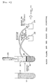
- Fig. 1 is a perspective view showing schematically a pipetting apparatus 30 according to the present invention.
- the pipetting apparatus 30 is used to pipette the blood plasma component and the red blood cell component which have been obtained by centrifugation to perform a preprocess for blood type test.
- a nozzle 32 for aspirating a blood sample is held by an XYZ robot 34 so as to be movable three-dimensionally.
- Fig. 2 shows a cross sectional view of a main part of the nozzle 32.
- the nozzle 32 is composed of a nozzle base 35, and a disposable tip serving as a nozzle tip 36.
- the pipetting apparatus in the embodiment of the present invention uses a disposable type nozzle tip.
- a distal end of the nozzle base 35 is forced into an upper opening of the nozzle tip 36 and is fitted therein.
- the nozzle tip 36 is fixed firmly to the nozzle base 35.
- the nozzle tip 36 has at its lower end a smaller orifice 36a from which the blood sample is aspirated and dispensed.
- the nozzle tip 36 may be made of a hard plastic material or the like, and the nozzle base 35 may be made of a metal.
- the XYZ robot 34 is composed of an X drive Portion 34x, an Y drive portion 34y and a Z drive portion 34z.
- an elevator 38 equipped with the nozzle 32 is mounted so as to be vertically movable.
- the elevator 38 has a limit switch 40 serving as a jamming sensor or the like.
- the limit switch 40 detects an external force imparted upwardly to the nozzle 32 and having a value greater than a predetermined force.
- a diluent pipette 42 for dispensing a diluent is fixedly mounted.
- An air hose 44 is connected at one end thereof to the nozzle 32 and at the other end thereof to a syringe 46 serving as a pump for causing aspirating and dispensing actions.
- a diluent hose 48 is connected at one end thereof to the diluent pipette 42 and at the other end thereof to a syringe 52 via an electromagnetic valve 50.
- a pressure sensor 54 for measuring an internal pressure of the air hose 44 is connected between the syringe 46 and the nozzle 32.
- a signal from the limit switch 40 is fed to the apparatus via a cable 56.
- test tube rack 60 placed on a pipetting table 58, a plurality of test tubes 62 each containing a blood sample which has been already subjected to centrifugation are held uprightly.
- Each test tube 62 contains the blood sample in which the blood plasma component and the red blood cell component are separated into an upper portion and a lower portion in the test tube 62, respectively.
- a dilution tray 68 equipped with a plurality of diluting containers 66, and a microplate 70.
- the microplate 70 there are provided a plurality of wells each serving as a recipient container for containing the blood plasma component or the diluted the red blood cell component.
- the microplate 70 is conveyed to an apparatus for blood type test, by which an agglutination test, for example, is made optically. Further, the agglutination test may be made visually.
- the nozzle tip is a disposable type. Therefore, a plurality of new nozzle tips are prepared on a nozzle tip stand 72, and the nozzle tip already used is exchanged with a new one. There is also provided a nozzle scrap tray 74.
- the device according to the present invention it is possible to aspirate the blood plasma component or the red blood cell component through the nozzle tip 36 of the nozzle 32 and then transfer it into other recipient container.
- This device may also be applied to purposes other than pipetting of the blood sample. Various kinds of applications are possible.
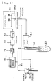
- Fig. 3 is a block diagram which shows diagrammatically the structure of the device of the embodiment according to the present invention.
- a piston 76 By moving a piston 76 up and down, inside volume of the syringe 46 varies, so that an aspirating pressure or a dispensing pressure is transmitted to the nozzle tip 36 of the nozzle 32 via the air hose 44 to perform the aspiration or dispensation of the blood sample.
- the internal pressure of the air hose 44 is detected by the pressure sensor 54, a sensor signal outputted from the pressure sensor 54 is amplified by a DC amplifier 78 and is then fed to an analog-digital converter 82 via a limiter circuit 80.
- the limiter circuit 80 functions as a protection circuit for suppressing any excessive input.
- the analog-digital converter 82 converts the sensor signal into a digital signal and feeds the digital signal to a control unit 84.
- the control unit 84 includes a computer, for example, for controlling the inside volume of the syringe 46, and the XYZ robot 34, etc.
- the control unit 84 also includes a viscosity measuring unit 86 and a table 88. The detailed of the viscosity measuring unit 86 and the table 88 will be described below.
- the data corresponding to the relationship between the viscosity and the required time is stored in the table 88.
- a predetermined initial aspiration pressure is produced by the pump under the monitoring of the control unit 84, and subsequent pressure changes are detected by the pressure sensor 54.
- the viscosity measuring unit 86 measures a time required from a point of time when the initial aspiration pressure is produced, to a point of time when the pressure reaches a predetermined pressure value ( ⁇ ). Then, the viscosity measuring unit 86 compare the measured time with the data storing in the table 88 to obtain the viscosity of the blood sample. The obtained viscosity is displayed in a display unit (not-shown), and the data representing the obtained viscosity is supplied to the control unit 84 and used for controlling the pump.
- the viscosity measuring unit 86 as described above has advantages as follows. Since the viscosity can be measured simultaneously with the aspiration of the blood sample, the unit 86 requires no additional time for measuring the viscosity, and realizes a very simple viscosity measurement. Further, it is unnecessary to prepare an additional blood sample specially for viscosity measurement.
- the viscosity measuring apparatus since it is possible to easily measure the viscosity of the liquid sample by measuring the required time, there is an advantage of enabling a simultaneous viscosity measurement during the aspiration of the liquid sample. Therefore, the viscosity measuring apparatus according to the present invention is particularly useful when employed in the pipetting apparatus for pipetting the blood sample or the like.
Landscapes
- Health & Medical Sciences (AREA)
- Life Sciences & Earth Sciences (AREA)
- Physics & Mathematics (AREA)
- Chemical & Material Sciences (AREA)
- Engineering & Computer Science (AREA)
- General Health & Medical Sciences (AREA)
- Biomedical Technology (AREA)
- General Physics & Mathematics (AREA)
- Immunology (AREA)
- Pathology (AREA)
- Biochemistry (AREA)
- Analytical Chemistry (AREA)
- Hematology (AREA)
- Ecology (AREA)
- Biophysics (AREA)
- Molecular Biology (AREA)
- Urology & Nephrology (AREA)
- Food Science & Technology (AREA)
- Medicinal Chemistry (AREA)
- Automatic Analysis And Handling Materials Therefor (AREA)
- Sampling And Sample Adjustment (AREA)
- Investigating Or Analysing Biological Materials (AREA)
Abstract
Description
- The present invention relates to a liquid viscosity measuring device and more particularly to a liquid viscosity measuring device which enables a simultaneous measurement of a viscosity of a liquid sample with aspiration of the liquid sample in a pipetting apparatus or the like.
- Various kinds of tests are conducted on a blood sample collected from a human body. For example, in a blood type test, as shown in Fig.4, a collected
blood sample 10 is put into atest tube 12 and then separated into ablood plasma component 14 and a redblood cell component 16 by centrifugation. Practically, a small quantity of whiteblood cell component 18 appears between theblood plasma component 14 and the redblood cell component 16. - A blood sample pipetting method which is carried out in a conventional pipetting apparatus generally comprises two processes, including a process of pipetting blood plasma and a process of pipetting red blood cells. In the blood plasma pipetting process, the
blood plasma component 14 is aspirated through anozzle tip 20, and then dispensed into a plurality ofother recipient containers 22 in a predetermined volume, respectively. In the red blood cell pipetting process, the redblood cell component 16 is aspirated through thenozzle tip 20, and then transferred to a diluting container (not shown) to be mixed with a diluent. Thereafter, the diluted redblood cell component 16 is aspirated again through thenozzle tip 20 and then dispensed into a plurality ofother recipient containers 24, respectively in a predetermined volume. - Blood type testing reagents (i.e., a reagent for the blood plasma component and a reagent for the red blood cell component) are then introduced into the
recipient containers - Subsequently, these
recipient containers containers - The viscosity of the red blood cell component is useful data for diagnosing diseases, and it is also a useful factor for determining an aspiration pressure to be set when pipetting the blood sample.
- However, in conventional pipetting apparatuses, there has been equipped with no viscosity measuring device, and the viscosity of the blood sample or the like has been measured by another measuring apparatus.
- As aforementioned, in the conventional pipetting apparatuses it has been impossible to measure the viscosity of the blood sample simultaneously with the pipetting operation of the blood sample. Therefore, means for enabling a simultaneous measurement of the viscosity of the blood sample during the pipetting operation has been so far desired.
- As an apparatus for measuring the viscosity of the liquid sample, a capillary viscometer, a rotational viscometer, a falling body viscometer, an oscillational viscometer, and the like are conventionally well known. However, it takes a long time to measure the viscosity with these conventional viscometers, and their operations are troublesome. Further, these viscometers require to prepare a predetermined volume of the blood sample to be used for the viscosity measurement, in addition to the blood sample to be used for the pipetting. Therefore, when measuring the viscosity of the blood sample by the conventional viscometers, there is a disadvantage in that recycling of the blood sample used for the viscosity measurement is difficult.
- This invention has been made in view of above problems. It is therefore an object of the present invention to provide a liquid viscosity measuring device capable of measuring a viscosity of a liquid sample simultaneously with the aspiration of the liquid sample.
- Another object of the present invention is to provide a pipetting apparatus which enables simultaneous viscosity measurement during the pipetting operation, without preparing another blood sample to be used only for the viscosity measurement.
- According to the present invention, the aforementioned object can be achieved by a liquid viscosity measuring device comprising: a viscosity table storing data corresponding to relationship between a viscosity of a liquid sample and a time required from a point of time when the liquid sample is aspirated under a predetermined initial aspiration pressure to a point of time when the aspiration pressure of an aspiration system reaches a predetermined value; and a viscosity measuring unit for measuring the required time for the liquid sample, and comparing the required time with the data in said table, thereby obtaining the viscosity of the liquid sample.
- According to the present invention, the aforementioned object can be also achieved by a pipetting apparatus having a liquid sample aspirating device including a nozzle tip for aspirating a liquid sample, an aspirating pump connected to the nozzle tip, and a pressure sensor for measuring a pressure in an aspiration system, wherein the pipetting apparatus further comprises a liquid viscosity measuring device as defined in Claim 1 which measures the viscosity of the liquid sample simultaneously with the aspiration of the liquid sample.
- According to the aforementioned construction, a viscosity table representing the relationship between the required time and the viscosity of the liquid sample is previously prepared. The viscosity measuring unit measures the required time for the liquid sample to obtain the viscosity of the liquid sample with reference to the data stored in the viscosity table.
- Therefore, it is possible to measure the viscosity of the liquid sample simultaneously with the aspiration of the liquid sample.
- If the apparatus according to the present invention is applied to a pipetting apparatus, there are advantages as follows. The viscosity of the blood sample can be measured simultaneously with the pipetting operation of the blood sample. Further, it is possible to measure the viscosity, without preparing a predetermined volume of a blood sample to be used only for the viscosity measurement.
- The principles of the present invention will now be described with reference to the accompanying drawings.
- Fig. 5 shows schematically a construction of an ordinary aspirating device used in a pipetting apparatus or the like. A
nozzle chip 20 is connected to apump 104 via anair hose 102. Thepump 104 is composed of acylinder 106 and apiston 108. Theair hose 102 is equipped with apressure sensor 110 for detecting an internal pressure of theair hose 102. - Fig. 6 shows changes of the pressure in the aspiration system which are detected by the
pressure sensor 110, after the initial aspiration pressure has been produced by pulling downwardly thepiston 108 as shown in Fig.5. As shown in Fig.6, as the viscosity becomes higher, the time required until the pressure returns from a predetermined pressure to an atmospheric pressure becomes longer. This means that if a predetermined pressure value is determined as β, the time required until a produced pressure reaches the predetermined value β differs depending on the viscosity of a liquid sample to be aspirated. - Fig. 7 shows the relationship between the required time and the viscosity. The relationship therebetween is approximately proportional. This relationship can be also proved by calculation.
- If the predetermined pressure value β is set, the table representing the relationship shown in Fig. 7 is prepared, and the required time is measured, then it is easy to obtain the viscosity. Namely, according to the present invention, the required time is measured and the viscosity is obtained on the basis of the measured result.
- Embodiments of the present invention will now be described with reference to the accompanying drawings.
- Fig. 1 is a perspective view showing schematically a
pipetting apparatus 30 according to the present invention. - In this embodiment, the
pipetting apparatus 30 is used to pipette the blood plasma component and the red blood cell component which have been obtained by centrifugation to perform a preprocess for blood type test. - As shown substantially in the roughly central portion of Fig. 1, a
nozzle 32 for aspirating a blood sample is held by an XYZrobot 34 so as to be movable three-dimensionally. - Fig. 2 shows a cross sectional view of a main part of the
nozzle 32. Thenozzle 32 is composed of anozzle base 35, and a disposable tip serving as anozzle tip 36. Thus, the pipetting apparatus in the embodiment of the present invention uses a disposable type nozzle tip. A distal end of thenozzle base 35 is forced into an upper opening of thenozzle tip 36 and is fitted therein. Thus, thenozzle tip 36 is fixed firmly to thenozzle base 35. Thenozzle tip 36 has at its lower end a smaller orifice 36a from which the blood sample is aspirated and dispensed. Thenozzle tip 36 may be made of a hard plastic material or the like, and thenozzle base 35 may be made of a metal. - In Fig. 1, the XYZ
robot 34 is composed of anX drive Portion 34x, anY drive portion 34y and aZ drive portion 34z. On theZ drive portion 34z, anelevator 38 equipped with thenozzle 32 is mounted so as to be vertically movable. Theelevator 38 has alimit switch 40 serving as a jamming sensor or the like. - The
limit switch 40 detects an external force imparted upwardly to thenozzle 32 and having a value greater than a predetermined force. - Onto the
Z drive portion 34z, adiluent pipette 42 for dispensing a diluent is fixedly mounted. Anair hose 44 is connected at one end thereof to thenozzle 32 and at the other end thereof to asyringe 46 serving as a pump for causing aspirating and dispensing actions. Adiluent hose 48 is connected at one end thereof to thediluent pipette 42 and at the other end thereof to asyringe 52 via an electromagnetic valve 50. - Between the
syringe 46 and thenozzle 32, apressure sensor 54 for measuring an internal pressure of theair hose 44 is connected. A signal from thelimit switch 40 is fed to the apparatus via acable 56. - On a test tube rack 60 placed on a pipetting table 58, a plurality of
test tubes 62 each containing a blood sample which has been already subjected to centrifugation are held uprightly. Eachtest tube 62, as shown in Fig.4, contains the blood sample in which the blood plasma component and the red blood cell component are separated into an upper portion and a lower portion in thetest tube 62, respectively. On a horizontal table 64 mounted on the pipetting table 58, there are provided adilution tray 68 equipped with a plurality of dilutingcontainers 66, and a microplate 70. On the microplate 70, there are provided a plurality of wells each serving as a recipient container for containing the blood plasma component or the diluted the red blood cell component. After all of the blood samples have been pipetted, the microplate 70 is conveyed to an apparatus for blood type test, by which an agglutination test, for example, is made optically. Further, the agglutination test may be made visually. - In the device according to the present invention, the nozzle tip is a disposable type. Therefore, a plurality of new nozzle tips are prepared on a nozzle tip stand 72, and the nozzle tip already used is exchanged with a new one. There is also provided a
nozzle scrap tray 74. - Therefore, in the device according to the present invention, it is possible to aspirate the blood plasma component or the red blood cell component through the
nozzle tip 36 of thenozzle 32 and then transfer it into other recipient container. This device may also be applied to purposes other than pipetting of the blood sample. Various kinds of applications are possible. - Fig. 3 is a block diagram which shows diagrammatically the structure of the device of the embodiment according to the present invention. By moving a
piston 76 up and down, inside volume of thesyringe 46 varies, so that an aspirating pressure or a dispensing pressure is transmitted to thenozzle tip 36 of thenozzle 32 via theair hose 44 to perform the aspiration or dispensation of the blood sample. The internal pressure of theair hose 44 is detected by thepressure sensor 54, a sensor signal outputted from thepressure sensor 54 is amplified by aDC amplifier 78 and is then fed to an analog-digital converter 82 via alimiter circuit 80. Thelimiter circuit 80 functions as a protection circuit for suppressing any excessive input. The analog-digital converter 82 converts the sensor signal into a digital signal and feeds the digital signal to acontrol unit 84. - The
control unit 84 includes a computer, for example, for controlling the inside volume of thesyringe 46, and theXYZ robot 34, etc. In this embodiment, thecontrol unit 84 also includes aviscosity measuring unit 86 and a table 88. The detailed of theviscosity measuring unit 86 and the table 88 will be described below. - As aforementioned, when a liquid is aspirated, a predetermined pressure used as an initial aspiration pressure is produced. In this case, there is a close relationship between the liquid viscosity and a time (required time) required from a point of time when the predetermined pressure is produced, to a point of time when the aspiration pressure reaches a certain pressure value (β).
- In view of the above, in the embodiment according to the present invention, the data corresponding to the relationship between the viscosity and the required time is stored in the table 88.
- Specifically, when the blood sample is aspirated by the
tip 36 in Fig.3, a predetermined initial aspiration pressure is produced by the pump under the monitoring of thecontrol unit 84, and subsequent pressure changes are detected by thepressure sensor 54. Theviscosity measuring unit 86 measures a time required from a point of time when the initial aspiration pressure is produced, to a point of time when the pressure reaches a predetermined pressure value (β). Then, theviscosity measuring unit 86 compare the measured time with the data storing in the table 88 to obtain the viscosity of the blood sample. The obtained viscosity is displayed in a display unit (not-shown), and the data representing the obtained viscosity is supplied to thecontrol unit 84 and used for controlling the pump. - The
viscosity measuring unit 86 as described above has advantages as follows. Since the viscosity can be measured simultaneously with the aspiration of the blood sample, theunit 86 requires no additional time for measuring the viscosity, and realizes a very simple viscosity measurement. Further, it is unnecessary to prepare an additional blood sample specially for viscosity measurement. - According to the present invention, since it is possible to easily measure the viscosity of the liquid sample by measuring the required time, there is an advantage of enabling a simultaneous viscosity measurement during the aspiration of the liquid sample. Therefore, the viscosity measuring apparatus according to the present invention is particularly useful when employed in the pipetting apparatus for pipetting the blood sample or the like.
-
- Fig. 1 is a perspective view showing schematically an embodiment of a pipetting apparatus according to the present invention;
- Fig. 2 is a cross-sectional view showing a main part of a nozzle;
- Fig. 3 is a block diagram showing schematically the pipetting apparatus of Fig. 1
- Fig. 4 is an explanatory view showing a pipetting operation of blood plasma and red blood cells for a preprocess of a blood type test;
- Fig. 5 is a schematic view showing an ordinary aspirating device;
- Fig. 6 is a characteristic graph showing the relationship between the elapsed time after an initial aspiration pressure is produced, and the pressure changes in an aspirating system, for respective liquid samples having different viscosities; and
- Fig. 7 is an explanatory view showing the relationship between the required time and the viscosity.
-
- 30
- pipetting apparatus
- 32
- nozzle
- 34
- XYZ robot
- 35
- nozzle base
- 36
- disposable tip
- 54
- pressure sensor
- 84
- control unit
- 86
- viscosity measuring unit
- 88
- table
Claims (2)
- A liquid viscosity measuring device comprising:(a) a viscosity table storing data corresponding to the relationship between a viscosity of a liquid sample and a time required from a point of time when the liquid sample is aspirated under a predetermined initial aspiration pressure to a point of time when the aspiration pressure of an aspiration system reaches a predetermined value; and(b) a viscosity measuring unit for measuring said required time for the liquid sample, and comparing said time with the data in said table to thereby obtain the viscosity of the liquid sample.
- A pipetting apparatus having a liquid sample aspirating device including a nozzle tip for aspirating a liquid sample, an aspirating pump connected to the nozzle tip, and a pressure sensor for measuring a pressure in an aspiration system, wherein the pipetting apparatus further comprises a liquid viscosity measuring device as defined in Claim 1 to measure the viscosity of a liquid sample simultaneously with the aspiration of the liquid sample.
Applications Claiming Priority (3)
| Application Number | Priority Date | Filing Date | Title |
|---|---|---|---|
| JP3271484A JP2552408B2 (en) | 1991-10-18 | 1991-10-18 | Liquid viscosity measuring device |
| JP271484/91 | 1991-10-18 | ||
| PCT/JP1992/001343 WO1993008475A1 (en) | 1991-10-18 | 1992-10-15 | Device for measuring viscosity of liquid |
Publications (3)
| Publication Number | Publication Date |
|---|---|
| EP0608425A1 true EP0608425A1 (en) | 1994-08-03 |
| EP0608425A4 EP0608425A4 (en) | 1994-11-23 |
| EP0608425B1 EP0608425B1 (en) | 1997-06-18 |
Family
ID=17500693
Family Applications (1)
| Application Number | Title | Priority Date | Filing Date |
|---|---|---|---|
| EP92921482A Expired - Lifetime EP0608425B1 (en) | 1991-10-18 | 1992-10-15 | Device for measuring viscosity of liquid |
Country Status (7)
| Country | Link |
|---|---|
| EP (1) | EP0608425B1 (en) |
| JP (1) | JP2552408B2 (en) |
| AU (1) | AU2771692A (en) |
| CA (1) | CA2121500A1 (en) |
| DE (1) | DE69220500T2 (en) |
| TW (1) | TW221672B (en) |
| WO (1) | WO1993008475A1 (en) |
Cited By (10)
| Publication number | Priority date | Publication date | Assignee | Title |
|---|---|---|---|---|
| US5750881A (en) * | 1995-07-13 | 1998-05-12 | Chiron Diagnostics Corporation | Method and apparatus for aspirating and dispensing sample fluids |
| US6158269A (en) * | 1995-07-13 | 2000-12-12 | Bayer Corporation | Method and apparatus for aspirating and dispensing sample fluids |
| DE10239530B4 (en) * | 2002-08-01 | 2006-06-01 | Göttfert Werkstoff-Prüfmaschinen GmbH | capillary |
| DE102004063358A1 (en) * | 2004-12-23 | 2006-07-06 | Georg-August-Universität Göttingen | Method for determining the viscosity and viscometer |
| EP1745851A1 (en) | 2005-07-22 | 2007-01-24 | Tecan Trading AG | Process, device and computerprogramm product for the classification of a liquid |
| WO2009104065A1 (en) * | 2008-02-21 | 2009-08-27 | Gilson Sas | Pipette system and method for measuring viscosity |
| US7634367B1 (en) | 2005-07-12 | 2009-12-15 | Ortho-Clinical Diagnostics, Inc. | Estimating fluidic properties and using them to improve the precision/accuracy of metered fluids and to improve the sensitivity/specificity in detecting failure modes |
| WO2013066806A1 (en) * | 2011-10-31 | 2013-05-10 | Freeslate, Inc. | Automated capillary viscometer |
| EP2730909A4 (en) * | 2011-07-08 | 2015-03-04 | Hitachi High Tech Corp | SOLID STATE EXTRACTION DEVICE AND VISCOSITY MEASURING DEVICE |
| EP2885621A4 (en) * | 2012-08-20 | 2016-04-27 | Us Health | CAPILLARY VISCOSIMETER AND MULTI-SCALE DIFFERENTIAL PRESSURE MEASUREMENT DEVICE |
Families Citing this family (7)
| Publication number | Priority date | Publication date | Assignee | Title |
|---|---|---|---|---|
| JP2688163B2 (en) * | 1993-06-04 | 1997-12-08 | アロカ株式会社 | Dispensing device |
| JP3740392B2 (en) * | 2001-07-17 | 2006-02-01 | アロカ株式会社 | Dispensing device |
| KR100643586B1 (en) * | 2005-05-16 | 2006-11-10 | 현대모비스 주식회사 | Metal Melt Flow Measurement System |
| JP2007132855A (en) * | 2005-11-11 | 2007-05-31 | Aloka Co Ltd | Liquid stirring method and liquid stirring device |
| US20130045498A1 (en) | 2010-03-01 | 2013-02-21 | Novozymes A/S | Viscosity pressure assay |
| KR102331945B1 (en) * | 2020-08-19 | 2021-12-01 | 주식회사 바이오리올로직스 | Multi-channel blood viscosity measuring device |
| CN113176178B (en) * | 2021-04-20 | 2023-02-07 | 安徽名士达新材料有限公司 | Paint production viscosity measuring device and implementation method thereof |
Family Cites Families (16)
| Publication number | Priority date | Publication date | Assignee | Title |
|---|---|---|---|---|
| JPS4840488A (en) * | 1971-09-21 | 1973-06-14 | ||
| JPS4879683A (en) * | 1972-01-28 | 1973-10-25 | ||
| DE2444148C3 (en) * | 1974-09-16 | 1981-09-17 | Dr. Karl Thomae Gmbh, 7950 Biberach | Capillary viscometer |
| US3999538A (en) * | 1975-05-22 | 1976-12-28 | Buren Philpot V Jun | Method of blood viscosity determination |
| CA1078643A (en) * | 1976-10-28 | 1980-06-03 | Robert I. Barker | Viscosity-stress tester |
| JPS56164957A (en) * | 1980-05-23 | 1981-12-18 | Aloka Co Ltd | Automatic dispenser |
| US4446726A (en) * | 1982-09-01 | 1984-05-08 | Deere & Company | Apparatus and method for measuring the filterability of a fluid at low temperatures |
| JPS60165552A (en) * | 1984-02-09 | 1985-08-28 | Toshiba Corp | Automatic biochemical analysis device |
| JPS6236537A (en) * | 1985-08-10 | 1987-02-17 | Konishiroku Photo Ind Co Ltd | Linkage measurement for surface tension, viscosity and density of solution |
| FR2604271A1 (en) * | 1986-09-19 | 1988-03-25 | Boillet Alain | Viscosity and tube coefficient calculator |
| JPH0625771B2 (en) * | 1987-01-07 | 1994-04-06 | 株式会社日立製作所 | Sample dispensing method |
| JPH07119685B2 (en) * | 1987-04-17 | 1995-12-20 | 東洋紡績株式会社 | Capillary viscometer |
| JPH02222826A (en) * | 1989-02-23 | 1990-09-05 | Shimadzu Corp | Capillary rheometer |
| JPH0316648A (en) * | 1989-06-14 | 1991-01-24 | Hitachi Ltd | Dispenser |
| JPH0399245A (en) * | 1989-09-12 | 1991-04-24 | Hiroyoshi Moriyama | Viscometer |
| JPH0641905B2 (en) * | 1990-02-28 | 1994-06-01 | 株式会社島津製作所 | Capillary viscometer |
-
1991
- 1991-10-18 JP JP3271484A patent/JP2552408B2/en not_active Expired - Fee Related
-
1992
- 1992-10-12 TW TW81108084A patent/TW221672B/zh active
- 1992-10-15 EP EP92921482A patent/EP0608425B1/en not_active Expired - Lifetime
- 1992-10-15 DE DE69220500T patent/DE69220500T2/en not_active Expired - Lifetime
- 1992-10-15 WO PCT/JP1992/001343 patent/WO1993008475A1/en not_active Ceased
- 1992-10-15 AU AU27716/92A patent/AU2771692A/en not_active Abandoned
- 1992-10-15 CA CA 2121500 patent/CA2121500A1/en not_active Abandoned
Cited By (14)
| Publication number | Priority date | Publication date | Assignee | Title |
|---|---|---|---|---|
| US6158269A (en) * | 1995-07-13 | 2000-12-12 | Bayer Corporation | Method and apparatus for aspirating and dispensing sample fluids |
| US5750881A (en) * | 1995-07-13 | 1998-05-12 | Chiron Diagnostics Corporation | Method and apparatus for aspirating and dispensing sample fluids |
| DE10239530B4 (en) * | 2002-08-01 | 2006-06-01 | Göttfert Werkstoff-Prüfmaschinen GmbH | capillary |
| DE102004063358A1 (en) * | 2004-12-23 | 2006-07-06 | Georg-August-Universität Göttingen | Method for determining the viscosity and viscometer |
| US7634367B1 (en) | 2005-07-12 | 2009-12-15 | Ortho-Clinical Diagnostics, Inc. | Estimating fluidic properties and using them to improve the precision/accuracy of metered fluids and to improve the sensitivity/specificity in detecting failure modes |
| CN1920575B (en) * | 2005-07-22 | 2012-10-24 | 泰肯贸易股份公司 | Method for the classification of a liquid |
| EP1745851A1 (en) | 2005-07-22 | 2007-01-24 | Tecan Trading AG | Process, device and computerprogramm product for the classification of a liquid |
| FR2927999A1 (en) * | 2008-02-21 | 2009-08-28 | Gilson Sas Soc Par Actions Sim | VISCOSIMETER COMPRISING A PIPETAGE SYSTEM, WITH IMPROVED PRECISION AND SIMPLIFIED DESIGN |
| WO2009104065A1 (en) * | 2008-02-21 | 2009-08-27 | Gilson Sas | Pipette system and method for measuring viscosity |
| US7904258B2 (en) | 2008-02-21 | 2011-03-08 | Gilson Sas | System for measuring viscosity |
| EP2730909A4 (en) * | 2011-07-08 | 2015-03-04 | Hitachi High Tech Corp | SOLID STATE EXTRACTION DEVICE AND VISCOSITY MEASURING DEVICE |
| US9494496B2 (en) | 2011-07-08 | 2016-11-15 | Hitachi High-Technologies Corporation | Solid-phase extraction apparatus and viscosity measurement apparatus |
| WO2013066806A1 (en) * | 2011-10-31 | 2013-05-10 | Freeslate, Inc. | Automated capillary viscometer |
| EP2885621A4 (en) * | 2012-08-20 | 2016-04-27 | Us Health | CAPILLARY VISCOSIMETER AND MULTI-SCALE DIFFERENTIAL PRESSURE MEASUREMENT DEVICE |
Also Published As
| Publication number | Publication date |
|---|---|
| JPH05107174A (en) | 1993-04-27 |
| TW221672B (en) | 1994-03-11 |
| WO1993008475A1 (en) | 1993-04-29 |
| AU2771692A (en) | 1993-05-21 |
| DE69220500D1 (en) | 1997-07-24 |
| CA2121500A1 (en) | 1993-04-29 |
| DE69220500T2 (en) | 1997-10-02 |
| JP2552408B2 (en) | 1996-11-13 |
| EP0608425A4 (en) | 1994-11-23 |
| EP0608425B1 (en) | 1997-06-18 |
Similar Documents
| Publication | Publication Date | Title |
|---|---|---|
| US5452619A (en) | Method for pipetting a blood sample | |
| EP0608423B1 (en) | Method of sucking liquid | |
| EP0608425B1 (en) | Device for measuring viscosity of liquid | |
| EP0607442B1 (en) | Method of diluting highly viscous liquid | |
| US5537880A (en) | Automatic pipetting apparatus with leak detection and method of detecting a leak | |
| US5158748A (en) | Automated dispensing and diluting system | |
| JP5686744B2 (en) | Automatic analyzer | |
| JP3065100B2 (en) | Sample pipetting method | |
| JPH0217448A (en) | Air type detection system | |
| JPH08501149A (en) | Liquid dispensing system | |
| CA2143674C (en) | Leakage detecting method for automatic pipetting apparatus | |
| CN101377521A (en) | Automatic analyzer | |
| WO1998053325A1 (en) | Fluid handler and method of handling a fluid | |
| EP2172782A1 (en) | Dispensing device and automatic analysis device | |
| EP1756587B1 (en) | Aspirator systems having an aspirator tip used as optical level detector and methods for using the same | |
| EP3073272B1 (en) | Method for automatic in vitro diagnosis | |
| JP3029388B2 (en) | Automatic dispensing device with leak detection function and leak detection method in the device | |
| JPH02196963A (en) | Detection of short sample of automatic dispenser | |
| JP2011137676A (en) | Dispensing apparatus, automatic analyzer, and method of measuring amount of liquid | |
| JPS61292557A (en) | Automatic chemical analyzer | |
| JPS63269061A (en) | Liquid specimen portionwise sampling method of automatic chemical analyser | |
| US20260050003A1 (en) | Dispenser and analysis device | |
| EP4136462B1 (en) | Automatic sampling method for handling whole blood | |
| US20240264192A1 (en) | Automatic analyzing apparatus and control method thereof | |
| JPS63109372A (en) | Sample portionwise collecting method and apparatus of automatic chemical analyzer |
Legal Events
| Date | Code | Title | Description |
|---|---|---|---|
| PUAI | Public reference made under article 153(3) epc to a published international application that has entered the european phase |
Free format text: ORIGINAL CODE: 0009012 |
|
| 17P | Request for examination filed |
Effective date: 19940517 |
|
| AK | Designated contracting states |
Kind code of ref document: A1 Designated state(s): DE FR GB IT |
|
| RIN1 | Information on inventor provided before grant (corrected) |
Inventor name: MAGEE, ROSIE, L. C/O MS. ANNIE LEWIS Inventor name: BIELARCZYK, GREGORY, A. Inventor name: KATO, YUKO Inventor name: KATAGI, HITOMI Inventor name: TAKEDA, MASAAKI Inventor name: KAWANABE, JUNICHI |
|
| A4 | Supplementary search report drawn up and despatched | ||
| AK | Designated contracting states |
Kind code of ref document: A4 Designated state(s): DE FR GB IT |
|
| GRAG | Despatch of communication of intention to grant |
Free format text: ORIGINAL CODE: EPIDOS AGRA |
|
| 17Q | First examination report despatched |
Effective date: 19960820 |
|
| GRAH | Despatch of communication of intention to grant a patent |
Free format text: ORIGINAL CODE: EPIDOS IGRA |
|
| GRAH | Despatch of communication of intention to grant a patent |
Free format text: ORIGINAL CODE: EPIDOS IGRA |
|
| GRAA | (expected) grant |
Free format text: ORIGINAL CODE: 0009210 |
|
| AK | Designated contracting states |
Kind code of ref document: B1 Designated state(s): DE FR GB IT |
|
| REF | Corresponds to: |
Ref document number: 69220500 Country of ref document: DE Date of ref document: 19970724 |
|
| ITF | It: translation for a ep patent filed | ||
| ET | Fr: translation filed | ||
| PLBE | No opposition filed within time limit |
Free format text: ORIGINAL CODE: 0009261 |
|
| STAA | Information on the status of an ep patent application or granted ep patent |
Free format text: STATUS: NO OPPOSITION FILED WITHIN TIME LIMIT |
|
| 26N | No opposition filed | ||
| REG | Reference to a national code |
Ref country code: GB Ref legal event code: IF02 |
|
| PGFP | Annual fee paid to national office [announced via postgrant information from national office to epo] |
Ref country code: FR Payment date: 20101004 Year of fee payment: 19 |
|
| PGFP | Annual fee paid to national office [announced via postgrant information from national office to epo] |
Ref country code: GB Payment date: 20100923 Year of fee payment: 19 |
|
| PGFP | Annual fee paid to national office [announced via postgrant information from national office to epo] |
Ref country code: DE Payment date: 20101029 Year of fee payment: 19 |
|
| PGFP | Annual fee paid to national office [announced via postgrant information from national office to epo] |
Ref country code: IT Payment date: 20101016 Year of fee payment: 19 |
|
| GBPC | Gb: european patent ceased through non-payment of renewal fee |
Effective date: 20111015 |
|
| REG | Reference to a national code |
Ref country code: FR Ref legal event code: ST Effective date: 20120629 |
|
| PG25 | Lapsed in a contracting state [announced via postgrant information from national office to epo] |
Ref country code: DE Free format text: LAPSE BECAUSE OF NON-PAYMENT OF DUE FEES Effective date: 20120501 |
|
| REG | Reference to a national code |
Ref country code: DE Ref legal event code: R119 Ref document number: 69220500 Country of ref document: DE Effective date: 20120501 |
|
| PG25 | Lapsed in a contracting state [announced via postgrant information from national office to epo] |
Ref country code: GB Free format text: LAPSE BECAUSE OF NON-PAYMENT OF DUE FEES Effective date: 20111015 Ref country code: FR Free format text: LAPSE BECAUSE OF NON-PAYMENT OF DUE FEES Effective date: 20111102 Ref country code: IT Free format text: LAPSE BECAUSE OF NON-PAYMENT OF DUE FEES Effective date: 20111015 |