EP0608006A2 - Analytical rotors and methods for analysis of biological fluids - Google Patents
Analytical rotors and methods for analysis of biological fluids Download PDFInfo
- Publication number
- EP0608006A2 EP0608006A2 EP94104814A EP94104814A EP0608006A2 EP 0608006 A2 EP0608006 A2 EP 0608006A2 EP 94104814 A EP94104814 A EP 94104814A EP 94104814 A EP94104814 A EP 94104814A EP 0608006 A2 EP0608006 A2 EP 0608006A2
- Authority
- EP
- European Patent Office
- Prior art keywords
- chamber
- rotor
- fluid
- flow
- separation
- Prior art date
- Legal status (The legal status is an assumption and is not a legal conclusion. Google has not performed a legal analysis and makes no representation as to the accuracy of the status listed.)
- Granted
Links
Images


Classifications
-
- G—PHYSICS
- G01—MEASURING; TESTING
- G01N—INVESTIGATING OR ANALYSING MATERIALS BY DETERMINING THEIR CHEMICAL OR PHYSICAL PROPERTIES
- G01N33/00—Investigating or analysing materials by specific methods not covered by groups G01N1/00 - G01N31/00
- G01N33/48—Biological material, e.g. blood, urine; Haemocytometers
- G01N33/483—Physical analysis of biological material
- G01N33/487—Physical analysis of biological material of liquid biological material
- G01N33/49—Blood
- G01N33/491—Blood by separating the blood components
-
- G—PHYSICS
- G01—MEASURING; TESTING
- G01N—INVESTIGATING OR ANALYSING MATERIALS BY DETERMINING THEIR CHEMICAL OR PHYSICAL PROPERTIES
- G01N21/00—Investigating or analysing materials by the use of optical means, i.e. using sub-millimetre waves, infrared, visible or ultraviolet light
- G01N21/01—Arrangements or apparatus for facilitating the optical investigation
- G01N21/03—Cuvette constructions
- G01N21/07—Centrifugal type cuvettes
-
- B—PERFORMING OPERATIONS; TRANSPORTING
- B01—PHYSICAL OR CHEMICAL PROCESSES OR APPARATUS IN GENERAL
- B01L—CHEMICAL OR PHYSICAL LABORATORY APPARATUS FOR GENERAL USE
- B01L2400/00—Moving or stopping fluids
- B01L2400/04—Moving fluids with specific forces or mechanical means
- B01L2400/0403—Moving fluids with specific forces or mechanical means specific forces
- B01L2400/0406—Moving fluids with specific forces or mechanical means specific forces capillary forces
-
- G—PHYSICS
- G01—MEASURING; TESTING
- G01N—INVESTIGATING OR ANALYSING MATERIALS BY DETERMINING THEIR CHEMICAL OR PHYSICAL PROPERTIES
- G01N35/00—Automatic analysis not limited to methods or materials provided for in any single one of groups G01N1/00 - G01N33/00; Handling materials therefor
- G01N2035/00178—Special arrangements of analysers
- G01N2035/00237—Handling microquantities of analyte, e.g. microvalves, capillary networks
Definitions
- the present invention relates generally to devices and methods for optically analyzing biological fluids.
- it relates to analytical rotors which allow for sample metering, separation of cellular material from fluid in the sample, and distribution of the separated fluid to a plurality of test wells for various biochemical analyses.
- Blood tests frequently require that potentially-interfering cellular components of the blood be separated from the blood plasma prior to testing of the plasma. It is also frequently desirable to divide the separated blood plasma into a plurality of discrete aliquots so that a variety of tests or assays may be performed on the blood. Such separation and division steps have heretofore been typically performed by centrifugation to separate the blood plasma from the cellular components, followed by manual or automated pipetting of the blood plasma into separate test wells. Such procedures are labor intensive and time-consuming, and various automated systems and methods have been proposed for providing multiple aliquots of plasma suitable for testing in a more efficient manner.
- centrifugal rotors which have been modified both to separate plasma from whole blood and to distribute the separated plasma into separate test wells.
- the use of such rotors can provide a plurality of discrete plasma volumes which may be tested or evaluated, all present within the centrifugal rotor, greatly enhancing the efficiency of automated testing procedures.
- the rotors should be capable of separating relatively small volumes of blood and should not require the use of a displacement fluid for effecting such separation. In particular, it would be desirable to have a separation efficiency greater than 10%, preferably greater than 20%, and more preferably greater than 30%.
- the rotors should be able to accommodate relatively large numbers of test wells, and the rotor design should be simple and amenable to low-cost manufacturing procedures. In particular, it would be desirable if the rotors were of unitary construction with no separable or movable parts.
- Plasma separation methods should be simple and be capable of being performed in relatively short times. In particular, the methods should require relatively few steps and should be capable of being performed with little or no intervention or manipulations by the operator. It would be particularly desirable if the methods required only rotation of the rotor in order to effect both the separation and distribution of the plasma.
- a first aspect of the invention is defined by patent claim 1.
- the rotor is a disk having means for mounting on a driver. At least a portion of the rotor comprises clear plastic.
- the biological sample is whole blood.
- the rotor may comprise a bulk fluid chamber adapted to receive a fluid; a metering chamber connected to the bulk fluid chamber, the metering chamber being poisitioned radially outward from the bulk fluid chamber such that the fluid in the bulk fluid chamber enters the metering chamber as the rotor spins; an overflow chamber connected to the metering chamber; and a connecting means through which the separation chamber communicates with the metering chamber, the connecting means being capable of alternately allowing or preventing flow of fluid into the separation chamber.
- the connecting means may be a capillary exit duct which prevents flow of fluid at a first rotation speed and allows flow of fluid at a second, higher rotatinal speed.
- the connecting means may include a siphon structure having a path segment which extends radially inward.
- the bulk fluid chamber may be a diluent chamber having a preloaded bulk amount of diluent.
- the bulk fluid chamber may be a blood capillary having a means for introducing the biological sample therein.
- the rotor of claim 1 may comprise a collection chamber connected to the separation chamber and a plurality of cuvettes disposed radially outward from the collection chamber and connected thereto.
- the collection chamber is positioned below the separation chamber and is connected to the separation chamber by an axial drainage port.
- the collection chamber may be positioned radially outward from the separation chamber.
- Each cuvette may contain reagents necessary for a biochemical analysis of the biological sample and the biochemical analysis may produce an optical effect when exposed to a light beam.
- a plurality of generally radial inlet channels may connect each cuvette to the collection chamber, wherein each inlet channel comprises means for defining two contiguous flow paths, each flow path being separately defined and distinct, whereby the fluid enters the cuvette through a first flow path and gas exits the cuvette through a second flow path.
- the first flow path may be on a side of the inlet channel in the direction or rotation of the rotor and the second flow path may be on a side of the inlet channel away from the direction of the rotation of the rotor.
- the first flow path and the second flow path have different depths.
- the first flow path and the second flow path may have different surface textures.
- the rotor may comprise a mixing chamber spaced radially inward from the separation chamber, the mixing chamber having a volume greater than that of the separation chamber, and a flow restrictive channel connecting the mixing chamber to the separation chamber.
- the rotor may further comprise a sample receptacle and a diluent chamber spaced radially-inward from the mixing chamber and connected thereto with non-flow-restrictive means for connecting the sample receptacle and the mixing chamber, whereby sample in the sample receptacle and diluent in the diluent chamber may be rapidly transferred in a radially outward direction to the mixing chamber but will be retained in the mixing chamber by the flow restrictive channel.
- the mixing chamber includes a cell retention region at a radially-outward periphery thereof.
- a further aspect of the invention is defined by claim 2.
- the flow rate into the overflow chamber is restricted relative to the flow rate into the metering chamber so that the metering chamber will preferentially fill with fluid.
- a further aspect of the invention is defined by claim 3.
- the sample chamber is a mixing chamber having a volume greater than that of the separation chamber.
- the rotor may further comprise a sample receptacle and a diluent chamber spaced radially-inward from the mixing chamber and connected thereto with non-restrictive connecting means, whereby sample in the sample receptacle and diluent in the diluent chamber may be rapidly transferred to the mixing chamber but will be retained in the mixing chamber by the flow restrictive channel.
- the flow restrictive channel may include a siphon structure having a path segment which extends radially inward.
- a second aspect of the invention is defined by claim 4.
- the reflective surface is oriented at about a 45 degree angle to the vertical axis of the rotor.
- the reflective surface may be a mirror.
- a further aspect of the invention is defined by claim 5.
- a further aspect of the invention is defined by claim 6.
- a further aspect of the invention is defined by claim 7.
- a further aspect of the invention is defined by claim 8.
- a third aspect of the invention is defined by claim 9.
- the method of claim 9 may comprise combining the biological fluid with a diluent in the receptacle region.
- the method may further comprise flowing separated fluid from the receptacle region into a plurality of test wells.
- a further aspect of the invention is defined by claim 10.
- the biological fluid continues to be introduced to the receptacle region while the separated fluid is removed through the port.
- the port is connected to an annular channel which allows the separated fluid to pass to an annularly-displaced collection chamber.
- the method of claim 9 and 10 may further comprise exposing the separated fluid to a reagent after the fluid is removed through the port.
- the method may further comprise examining the separated fluid after exposure to the reagent.
- the biological fluid is blood and the separated fluid is plasma.
- a further aspect of the invention is defined by claim 11.
- the receiving chamber is a separation chamber having a cell trap.
- the bulk fluid chamber is a diluent chamber and the step of introducing the fluid is carried out by preloading a diluent in the diluent chamber.
- the bulk fluid container may be a blood capillary and the step of introducing the fluid may be carried out by placing whole blood in the blood capillary.
- a further aspect of the invention is defined by claim 12.
- a further aspect of the invention is defined by claim 13.
- a further aspect of the invention is defined by claim 14.
- the light beam is oriented generally parallel to the vertical axis and is reflected to be oriented generally perpendicular to the vertical axis.
- the light beam may be oriented generally perpendicular to the vertical axis and may be reflected to be orientated generally parallel to the vertical axis.
- an improved cell separator comprises a centrifugal rotor having top and bottom surfaces and a central axis therethrough.
- a separation chamber is disposed at a first level within the rotor whereby a biological fluid (e.g., whole blood) can be separated into cell-free fluid (e.g., plasma) and cellular components in response to spinning of the rotor.
- the separation chamber usually includes a receptacle region, a cell trap spaced radially outward from the receptacle region, and a capillary region between the receptacle region and the cell trap.
- spinning of the rotor causes cells in the biological fluid to pass from the receptacle region through the capillary region into the cell trap.
- the capillary region inhibits backflow of the cellular material from the cell trap into the receptacle region where the clear biological fluid, e.g., plasma, remains.
- the separation chamber may be located radially outward from a sample chamber and connected thereto by a flow restrictive channel.
- biological fluid which is introduced to the sample chamber will flow radially outward into the separation chamber as the rotor is spun.
- the dimensions of the flow restrictive channel are selected to provide a desired flow rate into the separation chamber when the rotor is spun at a predetermined speed.
- the sample chamber may be a sample receptacle having an inlet opening or port which allows the user to introduce a volume of sample to be tested.
- the sample chamber may be a mixing chamber which receives sample from a sample chamber and diluent from a diluent chamber.
- such a mixing chamber may include a cell retention region at or near its radially outward periphery.
- the separation chamber will have dimensions selected to allow cellular components to separate from the biological fluid as the fluid continuously flows toward a means for collecting cell-free fluid within the chamber.
- the separation chamber will be annularly elongated with the flow restrictive channel located at or near one annular extremity and the means for collecting cell free fluid located at or near the opposite annular extremity. In this way, the separation chamber provides a sufficiently long flow path so that the residence time of the biological fluid (i.e., the time prior to the collection of cell-free fluid) is adequate to allow the cellular components to migrate radially outward into a retention region which is located at the radially outward periphery of the separation chamber.
- the analytical rotors of the present invention present invention preferably contain means for measurement and delivery of a predetermined volume of fluid to a receiving chamber, such as the separation chamber.
- the rotor typically comprises a bulk fluid chamber containing a bulk amount of fluid to be partitioned and a metering chamber connected to the bulk fluid chamber positioned radially outward from the bulk fluid chamber such that fluid enters the metering chamber as the rotor is spun.
- An overflow chamber is connected to the metering chamber for receiving excess fluid after the metering chamber is filled.
- the volume of the fluid remaining in the metering chamber corresponds to the predetermined volume. Either a biological fluid, such as whole blood, or a reagent, such as a diluent, may be placed in the bulk fluid chamber.
- a receiving chamber is positioned radially outward from the metering chamber and is connected to the metering chamber through a connecting means which prevents flow of fluid into the receiving chamber until the metering chamber contains the predetermined volume.
- the fluid can be held in the metering chamber for as long as desired before delivery to the receiving chamber.
- the connecting means is a capillary exit duct in which capillary forces prevent flow at a first rotational speed. At a second, higher rotational speed, centrifugal force exceeds the capillary force and the metering chamber is emptied.
- the connecting means can also be a siphon having an elbow that is substantially the same distance from the center of the rotor as the radially most inward point of the metering chamber.
- each of the cuvettes is connected to a central collection chamber by means of a generally radial inlet channel which has a discrete flow path for flow of liquid into the cuvette and a second discrete flow path for flow of gas out of the cuvette as the rotor is spun.
- the liquid flow path is on the side of the inlet channel in the direction of the rotation of the rotor and the gas evacuation flow path is on the side away from the direction of the rotation. The liquid is channeled into its flow path by differences in depth or surface texture between the two flow paths.
- the rotor may also comprise a plurality of reflective surfaces positioned radially inward from the cuvettes, the reflective surfaces being capable of deflecting a light beam by about 90°.
- a light beam oriented generally parallel to the axis of rotation of the rotor is deflected so that it passes horizontally through a fluid in the cuvette.
- the reflective surface is preferably oriented at about a 45° angle to the vertical axis of the rotor and is produced by a total internal reflection condition at the rotor material/air interface.
- the rotor of the present invention is preferably made of clear plastic, more preferably acrylic.
- Each cuvette typically contains reagents necessary for a biochemical analysis of the fluid in the cuvette.
- the biochemical analysis preferably produces an optical effect when exposed to the light beam which is then detected and analyzed.
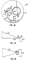
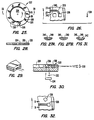
- Fig. 1 is a perspective view of a centrifugal rotor constructed in accordance with the principles of the present invention, with portions broken away.
- Figs. 1A and 1B illustrate alternate geometries for a separation chamber of the type employed in a centrifugal rotor constructed in accordance with the principles of the present invention.
- Fig. 2 is a top plan view of the centrifugal rotor of Fig. 1.
- Fig. 3 is a vertical cross-sectional view of the rotor of Figs. 1 and 2, taken along line 3-3 in Fig. 2.
- Fig. 4 is a vertical cross-sectional view of the rotor of Figs. 1 and 2, taken along line 4-4 in Fig. 2.
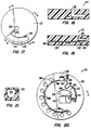
- Fig. 5 is a horizontal cross-sectional view of the rotor of Figs. 1-3, taken along line 5-5 in Fig. 3.
- Fig. 6 is a horizontal cross-sectional view of the rotor of Figs. 1-3, taken along line 6-6 in Figs. 3 and 4.
- Figs. 7-11 illustrate the method of the present invention utilizing the centrifugal rotor of Fig. 1.
- Fig. 12 illustrates an alternate embodiment of the centrifugal rotor of the present invention.
- Fig. 13 is a perspective view of an analytical rotor constructed in accordance with the principles of the present invention, with portions broken away.
- Fig. 14 is a plan view of the centrifugal rotor of Fig. 13.
- Fig. 15 is a cross-sectional view taken along line 15-15 of Fig. 14.
- Fig. 16 is a cross-sectional view taken along line 16-16 of Fig. 14.
- Fig. 17 is a plan view of an alternate rotor design.
- Fig. 18 is a cross-sectional view taken along line 18-18 of Fig. 17.
- Fig. 19 is a cross-sectional view taken along line 19-19 of Fig. 17.
- Fig. 20 is a plan view of a second alternate rotor design.
- Fig. 21 is a cross-sectional view taken along line 21-21 in Fig. 20.
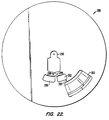
- Fig. 22 is a plan view of a rotor designed in accordance with one embodiment of the present invention in which the metering chamber is used to measure a precise volume of blood.
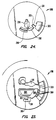
- Fig. 23 is a plan view of a rotor in which the metering chamber is used for diluent.
- Fig. 24 is a plan view of a rotor in which a siphon is used to control flow between the metering chamber and the separation chamber.
- Fig. 25 is a plan view of the bottom layer of a rotor made in accordance with the present invention.
- Fig. 26 is a plan view of the bottom layer of the rotor of Fig. 25 showing a cuvette, a curved inlet channel and a reflective surface.
- Fig. 27 shows two cross-sectional views along line 27-27 in Fig. 26.
- Fig. 28 is a cross-sectional view along line 28-28 of the bottom layer of the rotor in Fig. 25.
- Fig. 29 is perspective view of an inlet channel showing the direction of flow in the discrete flow paths.
- Fig. 30 s a cross-sectional view of the bottom layer of the rotor of the present invention showing the light path through the fluid in the cuvette.
- Fig. 31 is a cross-sectional view along line 31-31 in Fig. 32.
- Fig. 32 is a plan view of the rotor showing a cuvette, a straight inlet channel and a reflective surface.
- the present invention provides apparatus and methods for separating cellular components from biological fluids, and in particular for separating whole blood into plasma which may then be subjected to a wide variety of analytic procedures.
- the apparatus and methods will also provide for distribution of the separated plasma into a plurality of test wells within the rotor so that different analytic procedures may be performed without having to transfer aliquots of the plasma from the apparatus.
- the apparatus and method are able to separate very low volumes of blood, usually as low as about 0.03 cc, frequently as low as about 0.015 cc, and sometimes as low as about 0.005 cc, although the present invention is suitable for separating much larger volumes as well.
- the present invention does not require the use of a displacement medium for effecting the desired separation and distribution, and the apparatus design is very simple with no separate or moving parts required. Of course, it may be desirable in certain circumstances to provide such separate or moving parts, but they are not required in order to achieve the blood separation according to the method of the present invention.
- the apparatus is very easy to manufacture and can be produced at a very low cost, making the apparatus suitable for use as a disposable in testing whole-blood samples.
- the apparatus and method are able to separate precise volumes of blood without the need to premeasure the amount applied to the apparatus.
- the apparatus can further provide for automatic combination of the separated plasma with a reagent or diluent and can apportion substantially equal volumes of plasma among the plurality of test wells.
- diluents known to those skilled in the art are suitable for use in the present invention.
- standard diluents such as normal saline solution (0.5% NaCl in water), phosphate buffered solution, and Ringer's lactate solution and the like may be used.
- the apparatus is suitable for use with a variety of conventional analytic measurement devices, such as spectrophotometers and fluorometers, which allow the plasma in the test wells to be individually examined without the need to remove the plasma from the wells.
- conventional analytic measurement devices such as spectrophotometers and fluorometers, which allow the plasma in the test wells to be individually examined without the need to remove the plasma from the wells.
- the present invention is particularly suitable for separating cells from blood to produce plasma, it will be useful with a wide variety of other biological fluids, such as urine, sputum, semen, saliva, ocular lens fluid, cerebral fluid, spinal fluid, amniotic fluid, and tissue culture media, as well as food and industrial chemicals, and the like, where it may be desirable to separate cells and other interfering substances prior to analysis or assay.
- biological fluids such as urine, sputum, semen, saliva, ocular lens fluid, cerebral fluid, spinal fluid, amniotic fluid, and tissue culture media, as well as food and industrial chemicals, and the like, where it may be desirable to separate cells and other interfering substances prior to analysis or assay.
- the apparatus of the present invention includes a centrifugal rotor which is capable of being mounted on a conventional laboratory centrifuge of the type which is commercially available from suppliers, such as Beckman Instruments, Inc., Spinco Division, Fullerton, California; Fisher Scientific, Pittsburgh, Pennsylvania; VWR Scientific, San Francisco, California, and the like.
- the centrifugal rotors will include a receptacle or other coupling device suitable for mounting on a vertical drive shaft within the centrifuge.
- the particular design of the receptacle or coupling device will depend on the nature of the centrifuge, and it will be appreciated that the centrifugal rotor of the present invention may be adapted to be used with most types of centrifuges which are now available or which may become available in the future.
- the centrifugal rotor comprises a body structure which maintains a desired geometric pattern or relationship between a plurality of chambers and interconnecting passages, as described in more detail hereinbelow.
- the body will be a substantially solid plate with the chambers and passages formed as spaces or voids in an otherwise solid matrix.
- such solid plate structures may be formed by laminating a plurality of separately formed layers together into a composite structure where the chambers and passages are generally formed between adjacent layers.
- the individual layers may be formed by injection molding, machining, and combinations thereof, and will usually be joined together, typically using a suitable adhesive or by ultrasonic welding. The final enclosed volumes are formed when the layers are brought together.
- centrifugal rotor could also be formed as a plurality of discrete components, such as tubes, vessels, chambers, etc., arranged in a suitable structural framework. Such assemblies, however, are generally more difficult to manufacture and are therefore less desirable than those formed in a substantially solid plate.
- the centrifugal rotor may be formed from a wide variety of materials and may optionally include two or more materials. Usually, the materials will be transparent so that the presence and distribution of blood, plasma, and other reagents, may be observed within the various internal chambers and passages. Also, it is generally required that the test wells formed within the rotor have suitable optical paths formed therethrough so that the contents of the test well may be observed spectrophotometrically, fluorometrically, or by other visual assessment instruments. In the exemplary embodiment described below, the rotor is formed from acrylic resins having the required optical properties, at least in those areas which define the optical paths.
- the apparatus and method of the present invention are suitable for performing a wide variety of analytic procedures which are beneficially or necessarily performed on blood plasma.
- the analytic procedures will generally require that the blood plasma be combined with one or more reagents so that some visibly detectable change occurs in the plasma which may be related to measurement of a particular component or characteristic of the plasma.
- the plasma will undergo a reaction or other change which results in a change in color, fluorescence, luminescence, or the like, which may be measured by conventional spectrophotometers, fluorometers, light detectors, etc.
- immunoassays and other specific binding assays may be performed in the test wells.
- such assay procedures must be homogeneous and not require a separation step.
- it will be possible to accommodate heterogeneous assay systems by providing a means to separate blood plasma from the test wells after an immunological reaction step has occurred.
- the separation chamber will include a capillary barrier which divides the cell retention region from the fluid flow path between the flow restrictive channel and the cell-free fluid collection means. In this way, the cells which pass into the retention region as the rotor is spun may be retained within the retention region even during subsequent handling of the rotor.
- the rotor will contain a plurality of sample receptacles, separation chambers, and optionally mixing chambers and collection chambers. In this way, multiple blood samples may be simultaneously separated and optionally analyzed with all cellular separation steps being performed simultaneously.
- the flow rate restrictive channel will include a siphon structure having a path which extends radially inward and which (prior to "priming") prevents flow from the sample chamber into the separation chamber while the rotor is spinning.
- a siphon barrier is particularly advantageous in embodiments which employ a mixing chamber to allow initial introduction of sample and diluent without carryover into the separation chamber.
- the mixing chamber may be sufficient to provide a desired level of separation without a separation chamber.
- the provision of a flow restrictive outlet on the mixing chamber allows a sufficient fluid residence time within the mixing chamber so that the cellular components of the fluid can be separated radially outward into a retention region as the rotor is spun.
- the cell-containing biological fluid is introduced to the receptacle region within the analytical rotor.
- Spinning of the rotor causes a radially outward flow of the biological fluid through the flow restrictive channel into the separation chamber.
- continued spinning of the rotor causes cellular components of the fluid to migrate radially outward into the retention region at the periphery of the chamber where they are entrapped.
- the resulting cell-free fluid in contrast, flows along a flow path which is radially inward from the retention region and is continuously removed from the separation chamber through the collection means which is located at a position annularly spaced-apart from the flow channel entry point.
- the rotor can be designed to allow separation of a predetermined fluid volume without substantial carryover of the cellular components.
- the cell-containing biological fluid is transferred to a mixing chamber where it is combined with a diluent.
- the biological fluid and diluent are mixed in the mixing chamber, typically by reversing the rotational direction of the rotor or by alternately accelerating and decelerating the velocity of rotation in a single rotational direction.
- the cells can then be separated outward into a peripheral retention region by spinning the rotor.
- a flow restrictive outlet on the mixing chamber assures that there is sufficient residence time to effect a desired degree of separation.
- the fluid from the mixing chamber flows through the restrictive channel and into a separation chamber as described above. In this way, two stages of separation are achieved, assuring substantially complete separation of cellular components.
- the present invention also provides devices and methods for measuring and delivering predetermined volumes of fluid, such as a diluent or a biological fluid, to a receiving chamber in a centrifugal rotor.
- the measurement of the fluid is provided by a metering chamber of predetermined volume which is connected to a bulk fluid chamber.
- the bulk fluid chamber may contain a diluent, or other reagent, which is preloaded in the rotor for storage until the rotor is used.
- the bulk fluid chamber may be a capillary chamber which receives a biological fluid to be tested, for example blood.
- the fluid flowing into the metering chamber from the bulk fluid chamber fills the metering chamber, while excess fluid flows out of the metering chamber into an overflow chamber.
- the predetermined volume in the metering chamber is delivered to the receiving chamber through at least one connecting means which controls flow out of the metering chamber so that fluid is delivered to the receiving chamber only after some predetermined time. Typically, delivery is delayed until after the metering chamber is filled and it contains the predetermined volume of fluid.
- the connecting means is designed such that essentially no detectable fluid escapes from the metering chamber until it is emptied. No detectable fluid is considered to have escaped from the metering chamber if the total volume of fluid ultimately delivered to the receiving chamber is sufficiently accurate such that subsequent analyses are not adversely affected.
- the prevention of flow between the metering chamber and the receiving chamber can be accomplished in a number of ways.
- a capillary exit duct in which capillary forces prevent flow at a first rotational speed can be used. When the speed is increased to a second, higher rotational speed, centrifugal force exceeds the capillary force and the metering chamber is emptied.
- Other means can also be used to block flow at the first speed, for example, a membrane which ruptures only at the higher rotational speed can be inserted in the duct.
- a siphon having an elbow which is at substantially the same distance from the center of the rotor as the minimum radial point (i.e. , the radially most inward point) of the metering chamber.
- capillary action pulls the fluid just beyond the elbow.
- a siphon in which the fluid has moved to this point as a result of capillary action is considered to be "primed".
- the rotor is restarted and the combination of centrifugal and capillary forces pulls the fluid out of the metering chamber and into the receiving chamber.
- the present invention also provides devices and methods for optically analyzing biological fluids, and in particular for analyzing blood plasma after first separating it from cellular material in the separation chamber.
- the apparatus and methods provide for distribution of the separated plasma or diluted plasma into a plurality of cuvettes within the rotor so that different optical analytic procedures may be performed without having to transfer aliquots of the fluid from the apparatus.
- the present invention decreases variability in the analyses by providing uniform optical paths in each cuvette and avoiding the creation of air bubbles when filling the cuvette. Uniform optical paths are provided through the use of reflective surfaces in the rotor which deflect a light beam oriented parallel with the axis of rotation so that the beam passes horizontally through the cuvette. Alternatively, a horizontal (e.g.
- radial light beam may be deflected vertically after passing through the fluid.
- variations in the amount of fluid in the cuvette, distortions in the light path due to welding seams, or matter floating on the top of the fluid will not affect results.
- the creation of air bubbles is also avoided by the use of novel inlet channels which allow gas to exit through one flow path in the channel, while fluid enters through another flow path in the same channel.
- the rotor 10 is in the form of a substantially solid disk including a top layer 12, middle layer 14, and bottom layer 16 laminated together to form a composite structure.
- each of the layers 12, 14, and 16 will be composed of the same material, usually a transparent plastic such as an acrylate, but it is possible that the layers will be composed of different materials and that each layer may include two or more different materials forming different portions of the layer.
- the exposed surface of top layer 12 will be referred to as the top surface while the exposed surface of the bottom layer 16 will be referred to as the bottom surface.
- a receptacle 18 is formed in the bottom surface of layer 16 and is generally aligned with the vertical axis 20 of the rotor, as best observed in Figs. 3 and 4.
- the receptacle 18 is formed to mate with the drive shaft of a conventional centrifuge system, as described previously.
- the top surface 12 includes a blood application port 22 and four vent ports 24, 26, 28, and 30.
- the blood application port 22 and vent ports 24, 26, 28, and 30, penetrate the entire thickness of the top layer 12 and, as described in more detail hereinbelow, are aligned with various chambers formed in the middle layer 14 of the rotor 10. These penetrations may conveniently be formed in the top layer 12 by machining, e.g., drilling.
- the upper surface of middle layer 14 includes a plurality of chambers and passages formed therein.
- the chambers and passages may be formed by machining a disk having generally flat surfaces or may be formed by injection molding of a suitable plastic resin in order to initially form the disk.
- the middle layer 14 includes a metering chamber 40 having an inlet segment 42 which is generally aligned with the blood application port 22 in top layer 12.
- the metering chamber 40 is connected to an overflow chamber 44 by a connecting passage 46, with the overflow chamber being located radially outward from the metering chamber.
- a vent connector passage 48 extends from the radially-outward end of overflow chamber 44, first in a generally annular direction and thereafter in a generally radially-inward direction.
- the distal terminus 50 of passage 46 is aligned with vent port 28 in top layer 12 so that the outward radial extremity of overflow chamber 44 will be vented to the atmosphere during use of the rotor 10.
- the depth of metering chamber 40 and overflow chamber 44 will be selected to provide for capillary dimensions when the chambers are completed by lamination of the top layer 12. Typically, the depth will be in the range from about 0.1 to 1.0 mm, more typically being in the range from about 0.25 to 0.75 mm. Usually, the depth will be uniform for both chambers 40 and 46 as well as the connecting passage 46, although it will be possible to vary the depth so long as capillarity is maintained. Alternate embodiments for the metering chamber 40 and overflow chamber 44 are described in Figs. 22-24 and the accompanying text, below.
- a separation chamber 60 is formed in the upper surface of middle layer 14 and is disposed radially outward from the metering chamber 40.
- the separation chamber 60 includes a cell trap 62 formed at its radially-outward periphery and a receptacle region 65 formed along its radially-inward perimeter.
- a capillary region 66 is formed between the receptacle region 65 and the cell trap 62 in order to inhibit the backflow of cells after they have entered the cell trap 62 as a result of centrifugal separation.
- the receptacle region 65 provides a volume which is capable of receiving whole blood or other biological fluid (optionally combined with a diluent or reagent) and which retains the blood plasma or other separated fluid after centrifugation has been completed.
- An axial port 64 is conveniently formed as an annular passage which penetrates the entire thickness of middle layer 14 so that separated plasma may flow downward from receptacle region 65 of chamber 60 into a collection chamber 90 formed in bottom layer 16, as described in more detail hereinafter.
- the geometry of the separation chamber 60 may be varied considerably, as discussed in more detail in connection with Figs. 1A and 1B, below.
- the metering chamber 40 is connected to the separation chamber 60 by a short capillary passage 70 which terminates in a vertical wall 72 which forms the inner surface of axial port 64. Such termination of passage 70 will, of course, terminate the capillarity which would otherwise draw fluid through the passage.
- the volume of metering chamber 40 will vary depending on the desired application, but will usually be selected to be as low as possible to provide a desired amount of plasma to each of the test wells formed in bottom layer 16, as described in more detail hereinafter. Typically, the volume of metering chamber 40 will be in the range from about 0.005 to 0.05 cc, more typically being in the range from about 0.030 to 0.040 cc.
- the volume of overflow chamber 44 will generally be larger than that of the metering chamber 40 in order to accommodate excess blood which may be applied through blood application port 42. Generally, the volume of the overflow chamber 44 will be at least twice that of the metering chamber 40, typically being three or more times larger.
- the volume of separation chamber 60 will be selected to accommodate the expected volume of plasma and optionally reagent or diluent which can flow from the metering chamber 40 and reagent chamber 80 (as described below).
- the volume of the receptacle region 65 will be in the range from about 0.1 cc to 1.0 cc, more typically being in the range from about 0.25 cc to 0.50 cc.
- the volume of the cell trap 62 will depend at least in part on the volume of the receptacle region 65. In order to maximize the efficiency of separation, i.e., increase the amount of plasma obtained from a fixed amount of whole blood, it is desirable that the volume of the cell trap 62 be just large enough to accommodate the largest expected volume of cellular material. For whole blood this can be calculated based on the highest expected hematocrit, where the volume of cell trap 62 will then be the expected percentage of the volume of metering chamber 40.
- a reagent chamber 80 is also formed in the upper surface of middle layer 14 and connected to the separation chamber 60 through a capillary passage 82.
- the reagent chamber 80 will be disposed radially inward from the separation chamber 60 so that flow of reagent or diluent from the reagent chamber to the separation chamber 60 may be effected by spinning the rotor 14, as will be described in more detail hereinafter.
- the capillary passage 80 terminates with an open channel in wall 72. In this way, flow of reagent from chamber 80 will not occur in the absence of outward centrifugal force resulting from spinning of the rotor 10.
- a removable seal or barrier in chamber 82 or contain the reagent within a pouch or other package, to preserve the reagent and further assure that the reagent will not leak from chamber 80.
- a barrier, seal or package will be particularly desirable when the reagent is "prepackaged" into the centrifugal rotor 10 at a central preparation facility and later subjected to shipping, storing, and other handling procedures which might otherwise cause the reagent to degrade or leak.
- the reagent chamber 80 may have substantially greater depth than the metering chamber 40 since the ability to provide capillary flow is not necessary. Thus, it is easy to store volumes of reagent which are substantially greater than the volume of blood or plasma which is provided to separation chamber 60 from metering chamber 40.
- a collection chamber 90 is formed in the upper surface of bottom layer 16 and is disposed to receive plasma from the axial port 64.
- a plurality of test wells 92 is formed about the periphery of the collection chamber 90 and connected by short radial passages 94.
- the test wells 92 and radial passages 94 are described in more detail in Figs. 25-32 and the accompanying text, below.
- the test wells 92 will be spaced equally about the periphery of layer 16 in order to enhance the equal distribution of plasma to each of the test wells.
- the material above and below each test well 92 will usually be optically transparent in order to provide a clear optical path for visual assessment of the plasma in each well. Alternate optical paths through the rotor 10 may also be provided.
- the volume of the test wells 92 will usually be relatively low, typically being in the range from about 0.005 cc to 0.015 cc, more usually being in the range from about 0.008 cc to 0.010 cc. It is possible that liquid, dried, or lyophilized reagents may be provided within the individual test wells so that combination occurs with the plasma when it is introduced. Alternatively, the walls or bottom of the test well 92 may be derivatized with various active components, such as antibodies, antigens, receptors, or the like, which are intended to take part in the analytic procedure.
- the central feature of the separation chamber 60 is the capillary region 66, which is preferably an annular space having an inner arcuate boundary 200 and an outer arcuate boundary 202.
- the capillarity of region 66 is broken at each boundary 200 and 202 as the size of the adjoining regions, i.e., receptacle region 65 and cell trap 62, are increased to break the capillarity.
- fluid will be unable to flow through the capillary region 66 except when sufficient centrifugal force is applied by centrifugation.
- the shapes of the receptacle region 65 and cell trap 62 may vary substantially.
- the receptacle region 65 will generally be tapered so that the distance between opposed horizontal surfaces increases in the radially inward direction. Such increasing distance provides the desired capillarity break, as discussed above.
- the taper may be provided by inclining the lower surface relative to the horizontal plane (Fig. 1), inclining the upper surface relative to the horizontal plane (Fig. 1A), or inclining both surfaces (Fig. 1B).
- the angle between the opposed surfaces of receptacle region 65 is not critical, typically being between 0° and 40°, and usually being between 18° and 22°.
- the inner arcuate boundary 200 of the capillary region is usually formed contiguously with the narrow end of the tapered receptacle region which defines an arcuate aperture.
- the cell trap 62 is typically formed as an annular well which penetrates axially downward in the rotor and which is disposed contiguously with the outer arcuate boundary 202 of the annular space of the capillary region 66.
- the cell trap 62 may also extend upwardly, as illustrated in Fig. 1B, need not have a true annular shape.
- the geometry of collection chamber 90 may be modified to promote mixing of the separated biological fluid, e.g., plasma, with a diluent or reagent combined in separation chamber 60.
- the volume of the collection chamber 90 may be increased and a peripheral vertical wall 91 may be provided inside of radial passages 94.
- the radial passage 94 will be capillaries which serve to prevent loss of fluid from the test wells 92 after the separation and distribution steps are completed.
- the increased volume of collection chamber 90 and peripheral wall 91 both act to increase the retention time of liquid in chamber 90 as the rotor 10 is spun. Such increased retention time allows more thorough mixing prior to distribution.
- downward flow of plasma or other separated fluid through axial port 64 may be restricted by surface tension.
- the surface tension can be disrupted by abruptly stopping the spinning of the rotor 10 after separation has been achieved. Such cessation of spinning will cause the fluid to wet the wall of the region 65, allowing downflow.
- reagent chamber 80 will be filled with reagent to a desired volume. As illustrated, the chamber 80 is entirely filled, but it is also possible that the chamber will be partially filled.
- the reagent may be loaded into rotor 10 either at a central preparation facility or immediately prior to use by the user. In the later case, the reagent may be filled using a pipette through vent port 24.
- Whole blood may be loaded onto the rotor 10 through application port 24 in a volume greater than that which can be accommodated by measuring chamber 40.
- the blood As soon as the blood is applied through port 22, it will begin to flow laterally both into the main portion of chamber 40 and through passage 46 into overflow chamber 44 by capillary action. Since the flow area into measuring chamber 40 is substantially larger than that through passage 46, the measuring chamber will quickly fill with blood, with the overflow passing into overflow chamber 44. In this way, the blood applied through port 22 need not be carefully measured prior to application. After a time sufficient for the blood to partition between measuring chamber 40 and overflow chamber 44, the distribution of blood will be as illustrated in Fig. 7 with the capillary portion of chamber 40 being completely filled and overflow chamber 44 being partially filled.
- the rotor 10 will be centrifuged or spun at a rate sufficient to cause the blood from chamber 40 and reagent from chamber 80 to flow into separation chamber 60. Additionally, the blood in overflow chamber 44 will flow radially outward, as illustrated.
- the rotor 10 will be spun at a rate in the range from about 1500 rpm to 5000 rpm, more usually from about 2500 rpm to 4000 rpm, for a time in the range from about 20 seconds to 5 minutes, more typically being about 1 minute to 3 minutes, so that the cellular components of the blood will flow into trap 66 while the plasma will remain generally in the open portion of separation chamber 60.
- the rotor 10 After the separation of plasmas from the cellular components of the whole blood has been completed, spinning of the rotor 10 will be stopped and the separated plasma will flow downward through axial passage 64, as illustrated in Figs. 9 and 10. The cellular components remain in cell trap 66, and the overflow blood remains in overflow chamber 44 while the plasma has flowed downward into a pool P in collection chamber 90. The plasma may then be distributed substantially equally into the individual test wells 92 by further rotation of the rotor 10, typically at a rate in the range from about 900 rpm to 5000 rpm for a time in the range from about 10 seconds to 1 minute. After the desired distribution has been achieved, the rotor 10 may be removed from the centrifuge and the rotor transferred to an appropriate instrument, such as a spectrophotometer or fluorometer, for testing.
- an appropriate instrument such as a spectrophotometer or fluorometer
- the rotor 100 will generally be a laminate structure similar to rotor 10, with only a middle layer 102 being illustrated in Fig. 12.
- the upper layer will include an application port (not illustrated) which is aligned with an entry chamber 104 formed in the upper surface of layer 102.
- the entry chamber 104 is generally aligned with the vertical (spinning) axis of the rotor 100, and a pair of passages 106 and 108 extend radially outward from said entry port.
- Chamber 106 serves as the measuring chamber and has a larger cross-sectional area than passage 108 so that it will fill more rapidly.
- Chamber 108 serves as the overflow chamber so that it can take up any excess blood which is applied through entry chamber 104.
- a reagent chamber 110 is located radially outward from the entry chamber 104 and connects with a non-capillary passage 112, which is connected with the distal end of chamber 106 and extends generally radially outward.
- the rotor 100 may be spun to cause both the blood from passage 106 and reagent from chamber 110 to flow outward through passage 112 into a separation chamber 114.
- the cells generally to collect along the radially-outward wall 116 of chamber 114, and further to flow down a spirally-outward path 118 to collect in cell trap 120.
- the separation chamber 114 and cell trap 120 are vented through the terminal end 122 of event path 124.
- a drainage port 126 formed at the radially-inward periphery of separation chamber 114.
- the bottom floor of chamber 114 will be sloped downward in the inward radial direction to promote the drainage of plasma through port 126.
- a collection chamber will be formed beneath the drainage port 126 in a manner similar to that illustrated in Figs. 1-6.
- the rotor 10' includes a mounting receptacle 225 formed in the bottom surface of lower layer 206.
- the mounting receptacle 225 is suitable for mounting the rotor 10' on the spindle of a conventional centrifuge (not shown), as described hereinabove.
- a first separation assembly within the rotor 10' includes a sample receptacle 224 formed through the top layer 202 and into the bottom layer 206 which is joined to a separation chamber 210 by a flow restrictive channel 212.
- the separation chamber 210 includes a radially inward region 214 which generally defines a fluid flow path from the entry point of the flow channel 212 to a fluid outlet port 216.
- the separation chamber further includes a radially outward region 218 which forms a cell retention region which receives cells which are separated from the biological fluid as the rotor 10' is spun.
- rotor 10' includes a second separation assembly including sample receptacle 224', separation chamber 210', flow restrictive channel 212', and collection chamber 220'.
- the chambers and passageways in the second separation assembly are arranged in a pattern identical to that of the first separation assembly so that two equivalent separation and analytic procedures may be performed simultaneously. It will be appreciated that the rotor could be adapted to include three or more similar or identical separation assemblies to allow additional separation procedures to be performed simultaneously.
- the point at which flow channel 212 enters the separation chamber 210 be annularly-spaced apart from the collection port 216. In this way, the biological fluid will have a sufficient residence time within the separation chamber as the fluid flows from the entry point to the collection port.
- the flow passage 212 will be connected at one annular extremity of the collection chamber 210 while the collection port 216 will be located at or near the other annular extremity.
- the receptacle 224 will be sized to receive the entire volume of biological fluid which is to be separated.
- the cell retention region 218 within the separation chamber 210 will be sized to accommodate the maximum possible volume of cellular material which may be present in the sample. For blood samples, this will depend on the blood volume as well as the maximum expected hemocrit to be processed.
- the cell retention region will have a volume which is equal to about 4% to 10%, more usually being about 7%, of the volume of the sample region 214.
- the dimensions of the flow channel 212 will be selected to provide a flow rate of the biological sample into the separation chamber 210 which is sufficiently low to allow time for the cellular components to be separated from the fluid prior to the fluid reaching the outlet port 216.
- the particular dimensions will depend, of course, on the precise characteristics of the fluid as well as the speed at which the rotor is to be spun.
- flow channel having a width in the range from about 0.1 to 0.4 mm, more usually from about 0.15 to 0.25 mm, and a depth in the range from about 0.01 to 0.2 mm, more usually in the range from about 0.03 to 0.06 mm, will be suitable.
- the outlet port 216 may be connected to an annular overflow passage 222 which in turns is connected to an annularly spaced-apart collection chamber 220.
- cell-free fluid will begin flowing laterally through the connecting channel 222 into the collection chamber 220.
- the separation chamber 210 will be filled primarily with cell-free fluid, having a thin layer of separated cells formed adjacent the outer peripheral wall of the chamber. Over time, however, the thickness of the layer of cells will increase, with the interface between cells and the cell free fluid moving radially inward over time. The volume of the separation chamber 210, however, will be sufficient so that the entire sample will be separated before the cellular interface can move sufficiently close to the outlet port 216 to cause overflow of the cellular material.
- the cell-free fluid entering chamber 220 will be available immediately to react with any reagents which may be present within the chamber. In this way, an analytical reaction may be initiated prior to complete separation of the biological fluid. By the time the separation is complete, the desired analytical reaction may be substantially completed, requiring only a small additional reaction time.
- the cell-free fluid within collection chamber 220 may be observed directly through the rotor 10' without removal from the chamber 220.
- a vent port 226 will normally be provided near the inner peripheral wall of the collection chamber 220 in order to allow gases to vent as the chamber is filled with fluid.
- the rotor 10' is used by applying a biological sample to be separated into sample receptacle 224, usually while the rotor is at rest.
- the rotor 10' is then spun on a conventional centrifuge, typically at a speed in the range from about 1,500 rpm to 5,000 rpm, more usually being in the range from about 2,500 to 4,000 rpm, for a time in the range from about 20 seconds to five minutes, depending on the volume of fluid being separated.
- the direction of rotation is not critical but will usually be counterclockwise (i.e., the direction of arrow 211 in Fig. 1) so that cellular build-up will be more likely to move away from the outlet port 216.
- the collection chamber 220 may include reagent(s) which are selected to effect desired detection reactions, and reaction with the reagents may begin as soon as the cell-free fluid enters the collection chamber while the rotor continues to spin and additional fluid continues to be separated.
- a sample receptacle 228 is connected to a separation chamber 230 by means of a flow restrictive channel 232.
- Separation chamber 230 includes a cell retention region 234 at its outer periphery and a collection port 236 located near its inner periphery.
- the collection port 236 is annularly spaced apart from the inlet of the flow restrictive channel 232 in order to allow a sufficiently long flow path to provide sufficient residence time for the desired cellular separation.
- the collection port 236 is vertically disposed and connected to an underlying collection chamber 238 which in turn is connected to a plurality of analytical cuvette 240 located about the periphery of the rotor 227.
- a vent path 242 will be provided in order to allow gases to escape from the separation chamber 230 as the fluid enters.
- a biological sample is introduced to the sample receptacle 228, and the rotor is spun to cause the sample to enter the separation chamber 230 where the cellular components collect in the retention region 234.
- cell-free fluid will reach the collection port 236 and will begin to flow downward into the collection chamber 238. From the collection chamber, the cell-free fluid will move radially outward into the individual cuvettes where it may undergo reaction and subsequent analysis.
- the analytical rotor 244 comprises a disk-shaped rotor body 246 generally similar to the rotor 10' and rotor 227 described previously.
- the rotor 244 comprises a sample receptacle 248 having an inlet port 250.
- a diluent chamber 252 is formed adjacent the sample chamber 248 and will typically hold a container of "pre-packaged" diluent. Conveniently, the diluent container will be introduced at the time of rotor fabrication, but means may be provided for inserting such containers immediately prior to use.
- a mixing chamber 254 is located radially outward from both the sample chamber 248 and diluent chamber 252.
- the sample chamber 248 is connected to the mixing chamber 254 through a port 256
- the diluent chamber 252 is connected to the mixing chamber 254 through a port 258.
- Both the ports 256 and 258 are sufficiently large so that flow will not be substantially restricted between the chambers 248 and 252 and the mixing chamber 254.
- both the sample and the diluent may be substantially immediately transferred to the mixing chamber 254 by spinning the rotor 244.
- the mixing chamber 254 is connected to separation chamber 260 by a flow restrictive channel 262.
- the flow restrictive channel 262 typically a capillary channel, will prevent immediate transfer of the contents of mixing chamber 254 to the separation chamber 260.
- the sample and the diluent may be thoroughly mixed while present in chamber 254, typically by reversibly rotating the rotor 244 or by alternately accelerating and decelerating the velocity of rotation in a single direction.
- An exemplary pattern of reversible rotation is to accelerate from 0 to 1200 rpm in a first rotational direction over a period of three seconds, followed by stopping the rotation and accelerating from 0 to 1200 rpm in the opposite rotational direction over a period of three seconds.
- An exemplary pattern of acceleration and deceleration is to spin the rotor 244 at 500 rpm for a short period, e.g., about 1.6 seconds, followed by rapid acceleration to 4000 rpm for about 1.6 seconds. This pattern of acceleration and deceleration will also be repeated a sufficient number of times to effect a desired degree of mixing.
- the mixing chamber 254 may itself be formed as a separation chamber including a cell retention region 263 (best illustrated in Fig. 10) at its radially outward periphery.
- the cell retention region 263 is isolated by a capillary restriction 264, similar to capillary region 66 described in connection with Fig. 1.
- a first stage of cellular separation may be effected by spinning the rotor to cause the more dense cells to flow through capillary restriction 264 into the cell trap 263.
- the flow restrictive channel 262 is connected to a first annular extremity 264 of the separation chamber 260, while an outlet channel 266 is connected to the opposite annular extremity.
- a cell retention region 268 is formed at the radially outward periphery of chamber 260, so that cell-containing fluid entering the chamber through flow restrictive channel 262 will have sufficient residence time for the cellular material to separate out into the cell retention region 268 as the rotor is spun.
- the flow restrictive channel 262 will have an inlet port 280 (opening into separation chamber 260) which is spaced radially-outward from the outlet port 282 (which is connected to the mixing chamber 254).
- rotation of the rotor 244 will cause a fluid to flow at a controlled rate from the mixing chamber 254 to the separation chamber 260.
- the flow restrictive channel 262 may include a siphon structure defined by a path segment 284 which extends radially inward.
- a siphon structure will initially prevent flow from the mixing chamber 254 to the separation chamber 260. That is, so long as the path 264 is not filled with liquid, spinning of rotor 244 will not cause fluid from mixing chamber 254 to flow radially inward around the path 284 which defines the size and structure. Once spinning of the rotor 244 is stopped, however, capillary forces will cause fluid from the mixing chamber 254 to fill the flow restrictive channel 262, as described in connection with the previous embodiments.
- siphon structure is advantageous since it inhibits flow of the sample and diluent during the initial transfer from the sample chamber 248 and diluent chamber 252 which is effected by high speed spinning. Some carryover may occur, however, during the subsequent agitation step.
- a biological sample is introduced to sample receptacle 248 through port 250.
- Diluent will either be introduced or will be present in a package within the diluent chamber 252. In some cases, it may be necessary to open or pierce a diluent container in order to allow transfer of the diluent to the mixing chamber 254. In any event, the rotor 244 is then spun in order to effect transfer of the sample and diluent into the mixing chamber 254. At this point, the siphon structure in the flow restrictive channel 262 will substantially prevent any flow or carryover of fluids into the separation chamber 260.
- the contents of the chamber will be thoroughly mixed by subjecting the rotor 244 to a constantly reversing rotation or by alternately increasing and decreasing the velocity of rotation in the same direction, as described above. Such agitation will be continued for a time sufficient to assure complete mixing of the diluent sample. During such agitation, there may be some inadvertent loss or transfer of fluid from the mixing chamber 254 into the separation chamber 260, although the flow restrictive nature of channel 262 as well as the presence of the siphon structure will largely inhibit such transfer.
- the rotor 244 is held stationary for a time sufficient to allow fluid from the mixing chamber 254 to fill the flow restrictive channel 262 by capillary action. Once the channel 254 is filled, the rotor can be spun in order to effect the fluid flow from the mixing chamber to the separation chamber 260 by centrifugal force.
- the separation chamber 260 will fill with the fluid from the mixing chamber 254, and any cells which may be present will be trapped within the cell retention region 268, in a manner similar to that described for previous embodiments. Cell-free fluid from the separation chamber 260 will then flow into the distribution channel 264 and into a plurality of analytical chambers 286, e.g., optical cuvettes as described previously.
- Fig. 22 presents the middle layer 288 of a rotor such as is illustrated in Fig. 1.
- the middle layer 288 comprises a blood capillary 290 and a metering chamber 292 connected to the blood capillary 290 by a connecting channel 294.
- An overflow chamber 296 is connected to the metering chamber 292 through the overflow channel 298.
- the blood capillary 290, the metering chamber 292 and overflow chamber 296 preferably have capillary dimensions.
- An initial volume of fluid, such as whole blood, is introduced into the blood capillary 290 through blood application port 22 (shown in Fig. 1).
- the metering chamber 292 is sized to accept the predetermined amount of fluid desired to be split from the blood capillary 290.
- the first fluid entering the metering chamber 292 will fill the chamber, while excess fluid will overflow the metering chamber 292 and flow through connecting channel 294 and overflow channel 298 into overflow chamber 296.
- the overflow feature causes the original bulk amount of fluid to be split into two amounts, the first precisely measured amount and the excess fluid.
- the fluid entering the metering chamber 292 is delivered to a separation chamber 300 through an exit duct 302.
- the exit duct is typically of capillary dimensions which prevent flow of fluid at rotational speeds which cause filling of the metering chamber 292.
- the diameter of the capillary exit duct 302 is typically between about 0.05 mm and about 0.25 mm, preferably between about 0.075 mm and about 0.125 mm.
- the rotational speeds to fill the metering chamber typically generate a centrifugal force of about 5xg to about 42xg, preferably about 20xg to about 27xg.
- the rotor's speed is increased sufficiently to cause the centrifugal force to exceed the capillary force and thus drain the metering chamber 292 into the separation chamber 300.
- the higher rotational speeds are typically generate a centrifugal force exceeding about 45xg.
- Fig. 23 shows another embodiment of the middle layer 288 the present invention in which a diluent chamber 304 containing a bulk amount of diluent is connected to a diluent metering chamber 306, which is connected by a plurality of exit ducts 308 to the separation chamber 300.
- the diluent is preloaded in the rotor and stored in the rotor until use.
- a biological fluid, such as blood, is also delivered to the separation chamber 300 through a blood metering chamber 316.
- the diluent metering chamber operates on the same principles as the metering chamber described in Fig. 22. As the rotor spins the initial bulk volume of diluent partitions between the diluent metering chamber 306 and the overflow chamber 310.
- the diluent metering chamber 306 is sized to accept the predetermined amount of fluid desired to be split from the diluent chamber 304. The diluent entering the diluent metering chamber 306 will fill the chamber, while excess diluent will overflow the diluent metering chamber 306 and flow through connecting channel 312 and overflow channel 314 into overflow chamber 312.
- the overflow feature causes the original bulk diluent to be split into two amounts, the precisely measured amount and the excess fluid.
- the rotor's speed is increased sufficiently to cause the centrifugal force to exceed the capillary force and thus drain the diluent metering chamber 306 into the separation chamber 300.
- the rotational speeds to fill and empty the diluent metering chamber 306 are preferably the same as those to fill and empty the metering chamber 292 and to measure the blood.
- a rotor using a siphon 318 as the connecting means to control flow between the metering chamber 292 and separation chamber 300 is shown.
- the elbow 320 of the siphon 318 is positioned so that it is substantially the same distance from the center of the rotor as the radially most inward point of the metering chamber 292.
- Figs. 25-32 an analytical rotor comprising inlet channels, cuvettes, and reflective surfaces of the present invention are described in detail.
- the bottom layer 322 of a rotor as described in Fig. 1 is shown in Fig. 25. In some embodiments, however, the structures described below may be positioned radially outward from the separation chamber.
- the bottom layer 322 is composed of a transparent plastic, such as acrylic.
- the bottom layer 322 comprises a sample collection chamber 324 spaced radially inward from a plurality of peripheral cuvettes 326. Each cuvette 326 is connected to the collection chamber 324 by an inlet channel 328.
- the collection chamber may be formed in any shape, for instance, as a circle, a ring, or the like.
- Each inlet channel 328 comprises two discrete flow paths, a first flow path 340 for the flow of liquid into the cuvette 326 and a second flow path 342 for the flow of gas out of the cuvette.
- the term "discrete” as used herein refers to the fact that the two flow paths 340 and 342 are separately defined and distinct from each other.
- the inlet channels 328 are preferably curved so as to prevent backwash or carryover when the contents of the cuvettes are agitated to effect mixing of the contents. Thus, cross contamination between cuvettes is avoided.
- the use of the flow paths 340 and 342 allow gas to escape easily from the cuvette 326 as it is filled and thus prevent the formation of bubbles in the cuvette 326, which can deleteriously affect the results of optical analyses.
- Figs. 27A, 27B and 31 show three possible configurations in which liquid flow path 340 has a greater depth than the gas flow path 342. Because of its greater depth, the fluid will preferentially flow down path 340, leaving path 342 available for the evacuation of gas from the cuvette 328.
- the liquid flow path 340 may be on the side of the inlet channel 328 toward the direction of rotation of the rotor, as shown in Figs. 27A and 27B. In this configuration, centrifugal force will urge the liquid along the "leading" wall.
- the inlet channel is not curved, as shown in Fig. 32, the fluid flow path 340 may be in the center of the inlet channel 328, as shown in Fig. 31.
- the inlet channel 328 is conveniently formed such that it passes around a reflective surface 330 (described more fully, below). If a reflective surface 330 is present, the inlet channel 328 will typically pass around the reflective surface 330 on the side in the direction of rotation of the rotor. In the absence of a reflective surface 330, the inlet channel may be formed in any other generally radial configuration.
- inlet channels 328 having regions with different surface textures.
- the gas flow path 342 may be left unpolished, leaving a rough surface texture in that region, while the fluid flow path 340 is polished.
- the liquid flow path 340 may be treated so as to be hydrophilic whereas the gas flow path is treated so as to be hydrophobic.
- the manner of treatment to make the surfaces hydrophilic or hydrophobic is well known in the art and need not be recited here. Any known surface treatment may be used as desired so long as it is chemically inert to the fluids passing through the inlet channel 328.
- the rotor of this invention thus permits rapid filling of the cuvettes. Each cuvette is filled completely leaving little or no gas to interfere with subsequent optical analysis of the cuvettes contents.
- Fig. 30 it can be seen that optical analysis of the cuvette contents is facilitated by reflective surfaces 330 positioned radially inward from each cuvette 326 such that they are capable of deflecting a light beam between a generally vertical and a generally horizontal direction and which are oriented at about 45° from the vertical axis of the rotor.
- the "horizontal" and “vertical” directions are determined in relation to the axis of rotation of the rotor.
- the horizontal direction typically radial
- the vertical direction is parallel to the axis.
- the reflective surface 330 need not be oriented directly radially inward from the cuvette.
- the reflective surface 330 must be parallel to the side of the cuvette in the optical pathway. For instance, a horizontal light beam which does not pass radially through the rotor may be used. Thus, the reflective surface 330 will be placed on a radial plane different from that of the cuvette 326, as shown in Fig. 32.
- the reflective surface deflects a vertical light beam 332 from a light source 334 so that it passes radially through a fluid 336 in the cuvette 326. A light is then detected by the detector 338.
- the orientation of the reflective surfaces 330 is such that the positions of the detector 338 and light source 334 can be reversed. In the reversed configuration a horizontal light beam passes through the cuvette contents and is then deflected so that it passes vertically through the rotor where it is detected below the rotor.
- the reflective surfaces can be composed of any reflective surface known in the art which provides total internal reflection, and are typically air mirrors in which light is reflected at the acrylic-air interface. Alternatively, the surface can be coated or backed with a light reflective material.
- metering chambers may be provided in order to run simultaneous tests and assays which require different test conditions.
- multiple metering chambers may be provided to allow combination with different reagents or diluents in isolated separation chambers.
- a single metering chamber may be connected by separate capillary passages to control flow into separate separation chambers. In either case, assays and tests requiring different protocols can be carried out in a single rotor system.
Landscapes
- Health & Medical Sciences (AREA)
- Life Sciences & Earth Sciences (AREA)
- Engineering & Computer Science (AREA)
- Biomedical Technology (AREA)
- Chemical & Material Sciences (AREA)
- Physics & Mathematics (AREA)
- General Health & Medical Sciences (AREA)
- General Physics & Mathematics (AREA)
- Immunology (AREA)
- Pathology (AREA)
- Biochemistry (AREA)
- Hematology (AREA)
- Analytical Chemistry (AREA)
- Ecology (AREA)
- Biophysics (AREA)
- Molecular Biology (AREA)
- Urology & Nephrology (AREA)
- Food Science & Technology (AREA)
- Medicinal Chemistry (AREA)
- Investigating Or Analysing Biological Materials (AREA)
- Centrifugal Separators (AREA)
- Automatic Analysis And Handling Materials Therefor (AREA)
Abstract
Description
- The present invention relates generally to devices and methods for optically analyzing biological fluids. In particular, it relates to analytical rotors which allow for sample metering, separation of cellular material from fluid in the sample, and distribution of the separated fluid to a plurality of test wells for various biochemical analyses.
- Blood tests frequently require that potentially-interfering cellular components of the blood be separated from the blood plasma prior to testing of the plasma. It is also frequently desirable to divide the separated blood plasma into a plurality of discrete aliquots so that a variety of tests or assays may be performed on the blood. Such separation and division steps have heretofore been typically performed by centrifugation to separate the blood plasma from the cellular components, followed by manual or automated pipetting of the blood plasma into separate test wells. Such procedures are labor intensive and time-consuming, and various automated systems and methods have been proposed for providing multiple aliquots of plasma suitable for testing in a more efficient manner.
- Of particular interest to the present invention are centrifugal rotors which have been modified both to separate plasma from whole blood and to distribute the separated plasma into separate test wells. The use of such rotors can provide a plurality of discrete plasma volumes which may be tested or evaluated, all present within the centrifugal rotor, greatly enhancing the efficiency of automated testing procedures.
- Although a significant improvement over prior manual or partly manual procedures, previous modified centrifugal rotors have suffered from a number of deficiencies. Such rotors have frequently required the application of relatively large volumes of whole blood in order to achieve the desired separation and distribution. The efficiency of separation has frequently been low, typically on the order of 5% based on the initial amount of plasma available. Moreover, such rotors have frequently utilized complex designs which are difficult and costly to manufacture. Often, the rotors require various separable parts or components which are brought together or separated at different points in the centrifugation procedure. Previous centrifugal rotors have often been limited in the number of discrete samples and test wells which they can provide, and in some cases require the use of a separate displacement fluid to effect flow of blood and plasma through the system.
- For these reasons, it would be desirable to provide improved centrifugal rotors and methods suitable for separating blood into plasma and cellular components and for further distributing the separated plasma into a plurality of discrete test wells within the rotors. The rotors should be capable of separating relatively small volumes of blood and should not require the use of a displacement fluid for effecting such separation. In particular, it would be desirable to have a separation efficiency greater than 10%, preferably greater than 20%, and more preferably greater than 30%. The rotors should be able to accommodate relatively large numbers of test wells, and the rotor design should be simple and amenable to low-cost manufacturing procedures. In particular, it would be desirable if the rotors were of unitary construction with no separable or movable parts. Plasma separation methods should be simple and be capable of being performed in relatively short times. In particular, the methods should require relatively few steps and should be capable of being performed with little or no intervention or manipulations by the operator. It would be particularly desirable if the methods required only rotation of the rotor in order to effect both the separation and distribution of the plasma.
- A first aspect of the invention is defined by patent claim 1.
- Preferably, the rotor is a disk having means for mounting on a driver. At least a portion of the rotor comprises clear plastic. The biological sample is whole blood.
- The rotor may comprise a bulk fluid chamber adapted to receive a fluid; a metering chamber connected to the bulk fluid chamber, the metering chamber being poisitioned radially outward from the bulk fluid chamber such that the fluid in the bulk fluid chamber enters the metering chamber as the rotor spins; an overflow chamber connected to the metering chamber; and a connecting means through which the separation chamber communicates with the metering chamber, the connecting means being capable of alternately allowing or preventing flow of fluid into the separation chamber.
- In this case, the connecting means may be a capillary exit duct which prevents flow of fluid at a first rotation speed and allows flow of fluid at a second, higher rotatinal speed.
- The connecting means may include a siphon structure having a path segment which extends radially inward.
- The bulk fluid chamber may be a diluent chamber having a preloaded bulk amount of diluent.
- The bulk fluid chamber may be a blood capillary having a means for introducing the biological sample therein.
- The rotor of claim 1 may comprise a collection chamber connected to the separation chamber and a plurality of cuvettes disposed radially outward from the collection chamber and connected thereto.
- Preferably, the collection chamber is positioned below the separation chamber and is connected to the separation chamber by an axial drainage port.
- The collection chamber may be positioned radially outward from the separation chamber. Each cuvette may contain reagents necessary for a biochemical analysis of the biological sample and the biochemical analysis may produce an optical effect when exposed to a light beam.
- A plurality of generally radial inlet channels may connect each cuvette to the collection chamber, wherein each inlet channel comprises means for defining two contiguous flow paths, each flow path being separately defined and distinct, whereby the fluid enters the cuvette through a first flow path and gas exits the cuvette through a second flow path.
- In this case, the first flow path may be on a side of the inlet channel in the direction or rotation of the rotor and the second flow path may be on a side of the inlet channel away from the direction of the rotation of the rotor.
- Preferably, the first flow path and the second flow path have different depths.
- The first flow path and the second flow path may have different surface textures.
- The rotor may comprise a mixing chamber spaced radially inward from the separation chamber, the mixing chamber having a volume greater than that of the separation chamber, and a flow restrictive channel connecting the mixing chamber to the separation chamber.
- The rotor may further comprise a sample receptacle and a diluent chamber spaced radially-inward from the mixing chamber and connected thereto with non-flow-restrictive means for connecting the sample receptacle and the mixing chamber, whereby sample in the sample receptacle and diluent in the diluent chamber may be rapidly transferred in a radially outward direction to the mixing chamber but will be retained in the mixing chamber by the flow restrictive channel.
- In this case, the mixing chamber includes a cell retention region at a radially-outward periphery thereof.
- A further aspect of the invention is defined by
claim 2. - Preferably, the flow rate into the overflow chamber is restricted relative to the flow rate into the metering chamber so that the metering chamber will preferentially fill with fluid.
- A further aspect of the invention is defined by claim 3.
- Preferably, the sample chamber is a mixing chamber having a volume greater than that of the separation chamber.
- The rotor may further comprise a sample receptacle and a diluent chamber spaced radially-inward from the mixing chamber and connected thereto with non-restrictive connecting means, whereby sample in the sample receptacle and diluent in the diluent chamber may be rapidly transferred to the mixing chamber but will be retained in the mixing chamber by the flow restrictive channel.
- The flow restrictive channel may include a siphon structure having a path segment which extends radially inward.
- A second aspect of the invention is defined by claim 4.
- Preferably, the reflective surface is oriented at about a 45 degree angle to the vertical axis of the rotor.
- The reflective surface may be a mirror.
- A further aspect of the invention is defined by claim 5.
- A further aspect of the invention is defined by
claim 6. - A further aspect of the invention is defined by claim 7.
- A further aspect of the invention is defined by claim 8.
- A third aspect of the invention is defined by claim 9.
- The method of claim 9 may comprise combining the biological fluid with a diluent in the receptacle region.
- The method may further comprise flowing separated fluid from the receptacle region into a plurality of test wells.
- A further aspect of the invention is defined by
claim 10. - Preferably, the biological fluid continues to be introduced to the receptacle region while the separated fluid is removed through the port.
- In this case, the port is connected to an annular channel which allows the separated fluid to pass to an annularly-displaced collection chamber.
- The method of
claim 9 and 10 may further comprise exposing the separated fluid to a reagent after the fluid is removed through the port. - The method may further comprise examining the separated fluid after exposure to the reagent.
- In this case, the biological fluid is blood and the separated fluid is plasma.
- A further aspect of the invention is defined by claim 11.
- Preferably, the receiving chamber is a separation chamber having a cell trap.
- In this case, the bulk fluid chamber is a diluent chamber and the step of introducing the fluid is carried out by preloading a diluent in the diluent chamber.
- The bulk fluid container may be a blood capillary and the step of introducing the fluid may be carried out by placing whole blood in the blood capillary.
- A further aspect of the invention is defined by
claim 12. - A further aspect of the invention is defined by claim 13.
- A further aspect of the invention is defined by
claim 14. - Preferably, the light beam is oriented generally parallel to the vertical axis and is reflected to be oriented generally perpendicular to the vertical axis.
- In this case, the light beam may be oriented generally perpendicular to the vertical axis and may be reflected to be orientated generally parallel to the vertical axis.
- According to the present invention, an improved cell separator comprises a centrifugal rotor having top and bottom surfaces and a central axis therethrough. A separation chamber is disposed at a first level within the rotor whereby a biological fluid (e.g., whole blood) can be separated into cell-free fluid (e.g., plasma) and cellular components in response to spinning of the rotor. The separation chamber usually includes a receptacle region, a cell trap spaced radially outward from the receptacle region, and a capillary region between the receptacle region and the cell trap. In this way, spinning of the rotor causes cells in the biological fluid to pass from the receptacle region through the capillary region into the cell trap. After spinning is stopped, the capillary region inhibits backflow of the cellular material from the cell trap into the receptacle region where the clear biological fluid, e.g., plasma, remains.
- Alternatively, the separation chamber may be located radially outward from a sample chamber and connected thereto by a flow restrictive channel. Thus, biological fluid which is introduced to the sample chamber will flow radially outward into the separation chamber as the rotor is spun. The dimensions of the flow restrictive channel are selected to provide a desired flow rate into the separation chamber when the rotor is spun at a predetermined speed.
- The sample chamber may be a sample receptacle having an inlet opening or port which allows the user to introduce a volume of sample to be tested. Alternatively, the sample chamber may be a mixing chamber which receives sample from a sample chamber and diluent from a diluent chamber. Optionally, such a mixing chamber may include a cell retention region at or near its radially outward periphery.
- The separation chamber will have dimensions selected to allow cellular components to separate from the biological fluid as the fluid continuously flows toward a means for collecting cell-free fluid within the chamber. Typically, the separation chamber will be annularly elongated with the flow restrictive channel located at or near one annular extremity and the means for collecting cell free fluid located at or near the opposite annular extremity. In this way, the separation chamber provides a sufficiently long flow path so that the residence time of the biological fluid (i.e., the time prior to the collection of cell-free fluid) is adequate to allow the cellular components to migrate radially outward into a retention region which is located at the radially outward periphery of the separation chamber.
- The analytical rotors of the present invention present invention preferably contain means for measurement and delivery of a predetermined volume of fluid to a receiving chamber, such as the separation chamber. Thus, the rotor typically comprises a bulk fluid chamber containing a bulk amount of fluid to be partitioned and a metering chamber connected to the bulk fluid chamber positioned radially outward from the bulk fluid chamber such that fluid enters the metering chamber as the rotor is spun. An overflow chamber is connected to the metering chamber for receiving excess fluid after the metering chamber is filled. The volume of the fluid remaining in the metering chamber corresponds to the predetermined volume. Either a biological fluid, such as whole blood, or a reagent, such as a diluent, may be placed in the bulk fluid chamber.
- A receiving chamber is positioned radially outward from the metering chamber and is connected to the metering chamber through a connecting means which prevents flow of fluid into the receiving chamber until the metering chamber contains the predetermined volume. The fluid can be held in the metering chamber for as long as desired before delivery to the receiving chamber. Typically, the connecting means is a capillary exit duct in which capillary forces prevent flow at a first rotational speed. At a second, higher rotational speed, centrifugal force exceeds the capillary force and the metering chamber is emptied. The connecting means can also be a siphon having an elbow that is substantially the same distance from the center of the rotor as the radially most inward point of the metering chamber. As the rotor is spinning the fluid does not flow past the elbow. After the rotor stops, capillary forces "prime" the siphon by pulling fluid just around the elbow. When the rotor is restarted, the combination of centrifugal and capillary forces draw the remaining fluid out of the metering chamber into the receiving chamber.
- After the a predetermined volume of fluid is separated from cellular components, fluid is typically delivered to a plurality of peripheral test wells or cuvettes for optical analysis. In one embodiment, each of the cuvettes is connected to a central collection chamber by means of a generally radial inlet channel which has a discrete flow path for flow of liquid into the cuvette and a second discrete flow path for flow of gas out of the cuvette as the rotor is spun. Preferably, the liquid flow path is on the side of the inlet channel in the direction of the rotation of the rotor and the gas evacuation flow path is on the side away from the direction of the rotation. The liquid is channeled into its flow path by differences in depth or surface texture between the two flow paths.
- The rotor may also comprise a plurality of reflective surfaces positioned radially inward from the cuvettes, the reflective surfaces being capable of deflecting a light beam by about 90°. Typically, a light beam oriented generally parallel to the axis of rotation of the rotor is deflected so that it passes horizontally through a fluid in the cuvette. The reflective surface is preferably oriented at about a 45° angle to the vertical axis of the rotor and is produced by a total internal reflection condition at the rotor material/air interface.
- The rotor of the present invention is preferably made of clear plastic, more preferably acrylic. Each cuvette typically contains reagents necessary for a biochemical analysis of the fluid in the cuvette. The biochemical analysis preferably produces an optical effect when exposed to the light beam which is then detected and analyzed.
- Other advantages of the subject invention will be apparent to those skilled in the art from consideration of the detailed description of embodiments of the subject invention set forth below and of the attached drawings.
- Fig. 1 is a perspective view of a centrifugal rotor constructed in accordance with the principles of the present invention, with portions broken away.
- Figs. 1A and 1B illustrate alternate geometries for a separation chamber of the type employed in a centrifugal rotor constructed in accordance with the principles of the present invention.
- Fig. 2 is a top plan view of the centrifugal rotor of Fig. 1.
- Fig. 3 is a vertical cross-sectional view of the rotor of Figs. 1 and 2, taken along line 3-3 in Fig. 2.
- Fig. 4 is a vertical cross-sectional view of the rotor of Figs. 1 and 2, taken along line 4-4 in Fig. 2.
- Fig. 5 is a horizontal cross-sectional view of the rotor of Figs. 1-3, taken along line 5-5 in Fig. 3.
- Fig. 6 is a horizontal cross-sectional view of the rotor of Figs. 1-3, taken along line 6-6 in Figs. 3 and 4.
- Figs. 7-11 illustrate the method of the present invention utilizing the centrifugal rotor of Fig. 1.
- Fig. 12 illustrates an alternate embodiment of the centrifugal rotor of the present invention.
- Fig. 13 is a perspective view of an analytical rotor constructed in accordance with the principles of the present invention, with portions broken away.
- Fig. 14 is a plan view of the centrifugal rotor of Fig. 13.
- Fig. 15 is a cross-sectional view taken along line 15-15 of Fig. 14.
- Fig. 16 is a cross-sectional view taken along line 16-16 of Fig. 14.
- Fig. 17 is a plan view of an alternate rotor design.
- Fig. 18 is a cross-sectional view taken along line 18-18 of Fig. 17.
- Fig. 19 is a cross-sectional view taken along line 19-19 of Fig. 17.
- Fig. 20 is a plan view of a second alternate rotor design.
- Fig. 21 is a cross-sectional view taken along line 21-21 in Fig. 20.
- Fig. 22 is a plan view of a rotor designed in accordance with one embodiment of the present invention in which the metering chamber is used to measure a precise volume of blood.
- Fig. 23 is a plan view of a rotor in which the metering chamber is used for diluent.
- Fig. 24 is a plan view of a rotor in which a siphon is used to control flow between the metering chamber and the separation chamber.
- Fig. 25 is a plan view of the bottom layer of a rotor made in accordance with the present invention.
- Fig. 26 is a plan view of the bottom layer of the rotor of Fig. 25 showing a cuvette, a curved inlet channel and a reflective surface.
- Fig. 27 shows two cross-sectional views along line 27-27 in Fig. 26.
- Fig. 28 is a cross-sectional view along line 28-28 of the bottom layer of the rotor in Fig. 25.
- Fig. 29 is perspective view of an inlet channel showing the direction of flow in the discrete flow paths.
- Fig. 30 s a cross-sectional view of the bottom layer of the rotor of the present invention showing the light path through the fluid in the cuvette.
- Fig. 31 is a cross-sectional view along line 31-31 in Fig. 32.
- Fig. 32 is a plan view of the rotor showing a cuvette, a straight inlet channel and a reflective surface.
- The present invention provides apparatus and methods for separating cellular components from biological fluids, and in particular for separating whole blood into plasma which may then be subjected to a wide variety of analytic procedures. Conveniently, the apparatus and methods will also provide for distribution of the separated plasma into a plurality of test wells within the rotor so that different analytic procedures may be performed without having to transfer aliquots of the plasma from the apparatus. The apparatus and method are able to separate very low volumes of blood, usually as low as about 0.03 cc, frequently as low as about 0.015 cc, and sometimes as low as about 0.005 cc, although the present invention is suitable for separating much larger volumes as well. The present invention does not require the use of a displacement medium for effecting the desired separation and distribution, and the apparatus design is very simple with no separate or moving parts required. Of course, it may be desirable in certain circumstances to provide such separate or moving parts, but they are not required in order to achieve the blood separation according to the method of the present invention. As a result, the apparatus is very easy to manufacture and can be produced at a very low cost, making the apparatus suitable for use as a disposable in testing whole-blood samples. The apparatus and method are able to separate precise volumes of blood without the need to premeasure the amount applied to the apparatus. The apparatus can further provide for automatic combination of the separated plasma with a reagent or diluent and can apportion substantially equal volumes of plasma among the plurality of test wells. Various diluents known to those skilled in the art are suitable for use in the present invention. For instance, standard diluents such as normal saline solution (0.5% NaCl in water), phosphate buffered solution, and Ringer's lactate solution and the like may be used.
- In addition, the apparatus is suitable for use with a variety of conventional analytic measurement devices, such as spectrophotometers and fluorometers, which allow the plasma in the test wells to be individually examined without the need to remove the plasma from the wells.
- Although the present invention is particularly suitable for separating cells from blood to produce plasma, it will be useful with a wide variety of other biological fluids, such as urine, sputum, semen, saliva, ocular lens fluid, cerebral fluid, spinal fluid, amniotic fluid, and tissue culture media, as well as food and industrial chemicals, and the like, where it may be desirable to separate cells and other interfering substances prior to analysis or assay.
- The apparatus of the present invention includes a centrifugal rotor which is capable of being mounted on a conventional laboratory centrifuge of the type which is commercially available from suppliers, such as Beckman Instruments, Inc., Spinco Division, Fullerton, California; Fisher Scientific, Pittsburgh, Pennsylvania; VWR Scientific, San Francisco, California, and the like. Generally, the centrifugal rotors will include a receptacle or other coupling device suitable for mounting on a vertical drive shaft within the centrifuge. The particular design of the receptacle or coupling device will depend on the nature of the centrifuge, and it will be appreciated that the centrifugal rotor of the present invention may be adapted to be used with most types of centrifuges which are now available or which may become available in the future.
- The centrifugal rotor comprises a body structure which maintains a desired geometric pattern or relationship between a plurality of chambers and interconnecting passages, as described in more detail hereinbelow. Usually, the body will be a substantially solid plate with the chambers and passages formed as spaces or voids in an otherwise solid matrix. Conveniently, such solid plate structures may be formed by laminating a plurality of separately formed layers together into a composite structure where the chambers and passages are generally formed between adjacent layers. The individual layers may be formed by injection molding, machining, and combinations thereof, and will usually be joined together, typically using a suitable adhesive or by ultrasonic welding. The final enclosed volumes are formed when the layers are brought together. Of course, the centrifugal rotor could also be formed as a plurality of discrete components, such as tubes, vessels, chambers, etc., arranged in a suitable structural framework. Such assemblies, however, are generally more difficult to manufacture and are therefore less desirable than those formed in a substantially solid plate.
- The centrifugal rotor may be formed from a wide variety of materials and may optionally include two or more materials. Usually, the materials will be transparent so that the presence and distribution of blood, plasma, and other reagents, may be observed within the various internal chambers and passages. Also, it is generally required that the test wells formed within the rotor have suitable optical paths formed therethrough so that the contents of the test well may be observed spectrophotometrically, fluorometrically, or by other visual assessment instruments. In the exemplary embodiment described below, the rotor is formed from acrylic resins having the required optical properties, at least in those areas which define the optical paths.
- The apparatus and method of the present invention are suitable for performing a wide variety of analytic procedures which are beneficially or necessarily performed on blood plasma. The analytic procedures will generally require that the blood plasma be combined with one or more reagents so that some visibly detectable change occurs in the plasma which may be related to measurement of a particular component or characteristic of the plasma. Preferably, the plasma will undergo a reaction or other change which results in a change in color, fluorescence, luminescence, or the like, which may be measured by conventional spectrophotometers, fluorometers, light detectors, etc. In some cases, immunoassays and other specific binding assays may be performed in the test wells. Generally, however, such assay procedures must be homogeneous and not require a separation step. In other cases, it will be possible to accommodate heterogeneous assay systems by providing a means to separate blood plasma from the test wells after an immunological reaction step has occurred.
- Conventional blood assays which may be performed include glucose, lactate dehydrogenase, serum glutamic-oxaloacetic transaminase (SGOT), serum glutamic-pyruvic transaminase (SGPT), blood urea (nitrogen) (BUN), total protein, alkalinity, phosphatase, bilirubin, calcium, chloride, sodium, potassium, magnesium, and the like. This list is not exhaustive and is intended merely as being exemplary of the assays which may be performed using the apparatus and method of the present invention. Usually, these tests will require that the blood plasma be combined with one or more reagents which result in a visually detectable, usually photometrically detectable, change in the plasma. The reagents which are required are well known and amply described in the patent and scientific literature.
- In one embodiment, the separation chamber will include a capillary barrier which divides the cell retention region from the fluid flow path between the flow restrictive channel and the cell-free fluid collection means. In this way, the cells which pass into the retention region as the rotor is spun may be retained within the retention region even during subsequent handling of the rotor.
- In another embodiment of the present invention, the rotor will contain a plurality of sample receptacles, separation chambers, and optionally mixing chambers and collection chambers. In this way, multiple blood samples may be simultaneously separated and optionally analyzed with all cellular separation steps being performed simultaneously.
- In yet another preferred embodiment, the flow rate restrictive channel will include a siphon structure having a path which extends radially inward and which (prior to "priming") prevents flow from the sample chamber into the separation chamber while the rotor is spinning. The use of such a siphon barrier is particularly advantageous in embodiments which employ a mixing chamber to allow initial introduction of sample and diluent without carryover into the separation chamber.
- In an alternate embodiment, the mixing chamber may be sufficient to provide a desired level of separation without a separation chamber. The provision of a flow restrictive outlet on the mixing chamber allows a sufficient fluid residence time within the mixing chamber so that the cellular components of the fluid can be separated radially outward into a retention region as the rotor is spun.
- According to a method of the present invention, the cell-containing biological fluid is introduced to the receptacle region within the analytical rotor. Spinning of the rotor causes a radially outward flow of the biological fluid through the flow restrictive channel into the separation chamber. Within the separation chamber, continued spinning of the rotor causes cellular components of the fluid to migrate radially outward into the retention region at the periphery of the chamber where they are entrapped. The resulting cell-free fluid, in contrast, flows along a flow path which is radially inward from the retention region and is continuously removed from the separation chamber through the collection means which is located at a position annularly spaced-apart from the flow channel entry point. In this way, sufficient residence time is provided so that the cellular components may be substantially completely separated prior to removal of the fluid fraction. By properly selecting the volume of the biological fluid, the flow rate of the restrictive flow channel, and the volume of the cell retention region, the rotor can be designed to allow separation of a predetermined fluid volume without substantial carryover of the cellular components.
- In an alternate method, the cell-containing biological fluid is transferred to a mixing chamber where it is combined with a diluent. The biological fluid and diluent are mixed in the mixing chamber, typically by reversing the rotational direction of the rotor or by alternately accelerating and decelerating the velocity of rotation in a single rotational direction. The cells can then be separated outward into a peripheral retention region by spinning the rotor. A flow restrictive outlet on the mixing chamber assures that there is sufficient residence time to effect a desired degree of separation. Optionally, the fluid from the mixing chamber flows through the restrictive channel and into a separation chamber as described above. In this way, two stages of separation are achieved, assuring substantially complete separation of cellular components.
- The present invention also provides devices and methods for measuring and delivering predetermined volumes of fluid, such as a diluent or a biological fluid, to a receiving chamber in a centrifugal rotor. The measurement of the fluid is provided by a metering chamber of predetermined volume which is connected to a bulk fluid chamber. The bulk fluid chamber may contain a diluent, or other reagent, which is preloaded in the rotor for storage until the rotor is used. Alternatively, the bulk fluid chamber may be a capillary chamber which receives a biological fluid to be tested, for example blood. The fluid flowing into the metering chamber from the bulk fluid chamber fills the metering chamber, while excess fluid flows out of the metering chamber into an overflow chamber.
- The predetermined volume in the metering chamber is delivered to the receiving chamber through at least one connecting means which controls flow out of the metering chamber so that fluid is delivered to the receiving chamber only after some predetermined time. Typically, delivery is delayed until after the metering chamber is filled and it contains the predetermined volume of fluid. The connecting means is designed such that essentially no detectable fluid escapes from the metering chamber until it is emptied. No detectable fluid is considered to have escaped from the metering chamber if the total volume of fluid ultimately delivered to the receiving chamber is sufficiently accurate such that subsequent analyses are not adversely affected.
- The prevention of flow between the metering chamber and the receiving chamber can be accomplished in a number of ways. For instance, a capillary exit duct in which capillary forces prevent flow at a first rotational speed can be used. When the speed is increased to a second, higher rotational speed, centrifugal force exceeds the capillary force and the metering chamber is emptied. Other means can also be used to block flow at the first speed, for example, a membrane which ruptures only at the higher rotational speed can be inserted in the duct.
- Other embodiments utilize a siphon having an elbow which is at substantially the same distance from the center of the rotor as the minimum radial point (i.e., the radially most inward point) of the metering chamber. After the metering chamber is filled and the rotor is stopped, capillary action pulls the fluid just beyond the elbow. A siphon in which the fluid has moved to this point as a result of capillary action is considered to be "primed". The rotor is restarted and the combination of centrifugal and capillary forces pulls the fluid out of the metering chamber and into the receiving chamber.
- It is also possible to serialize several metering chambers in a single rotor. Fluid overflowing from a first metering chamber enters a second metering chamber of a precise, predetermined size. The excess from the second metering chamber then overflows into a third metering chamber, etc. Each metering chamber in the rotor typically feeds a separate receiving chamber.
- The present invention also provides devices and methods for optically analyzing biological fluids, and in particular for analyzing blood plasma after first separating it from cellular material in the separation chamber. The apparatus and methods provide for distribution of the separated plasma or diluted plasma into a plurality of cuvettes within the rotor so that different optical analytic procedures may be performed without having to transfer aliquots of the fluid from the apparatus. Conveniently, the present invention decreases variability in the analyses by providing uniform optical paths in each cuvette and avoiding the creation of air bubbles when filling the cuvette. Uniform optical paths are provided through the use of reflective surfaces in the rotor which deflect a light beam oriented parallel with the axis of rotation so that the beam passes horizontally through the cuvette. Alternatively, a horizontal (e.g., radial) light beam may be deflected vertically after passing through the fluid. Using either embodiment, variations in the amount of fluid in the cuvette, distortions in the light path due to welding seams, or matter floating on the top of the fluid will not affect results. The creation of air bubbles is also avoided by the use of novel inlet channels which allow gas to exit through one flow path in the channel, while fluid enters through another flow path in the same channel.
- Referring now to Figs. 1-6, a
centrifugal rotor 10 constructed in accordance with the principles of the present invention will be described in detail. Therotor 10 is in the form of a substantially solid disk including atop layer 12,middle layer 14, andbottom layer 16 laminated together to form a composite structure. Typically, each of thelayers top layer 12 will be referred to as the top surface while the exposed surface of thebottom layer 16 will be referred to as the bottom surface. Areceptacle 18 is formed in the bottom surface oflayer 16 and is generally aligned with thevertical axis 20 of the rotor, as best observed in Figs. 3 and 4. Thereceptacle 18 is formed to mate with the drive shaft of a conventional centrifuge system, as described previously. - The
top surface 12 includes ablood application port 22 and fourvent ports blood application port 22 and ventports top layer 12 and, as described in more detail hereinbelow, are aligned with various chambers formed in themiddle layer 14 of therotor 10. These penetrations may conveniently be formed in thetop layer 12 by machining, e.g., drilling. The upper surface ofmiddle layer 14 includes a plurality of chambers and passages formed therein. The chambers and passages may be formed by machining a disk having generally flat surfaces or may be formed by injection molding of a suitable plastic resin in order to initially form the disk. - The
middle layer 14 includes ametering chamber 40 having aninlet segment 42 which is generally aligned with theblood application port 22 intop layer 12. Themetering chamber 40 is connected to anoverflow chamber 44 by a connectingpassage 46, with the overflow chamber being located radially outward from the metering chamber. Avent connector passage 48 extends from the radially-outward end ofoverflow chamber 44, first in a generally annular direction and thereafter in a generally radially-inward direction. Thedistal terminus 50 ofpassage 46 is aligned withvent port 28 intop layer 12 so that the outward radial extremity ofoverflow chamber 44 will be vented to the atmosphere during use of therotor 10. - The depth of
metering chamber 40 andoverflow chamber 44 will be selected to provide for capillary dimensions when the chambers are completed by lamination of thetop layer 12. Typically, the depth will be in the range from about 0.1 to 1.0 mm, more typically being in the range from about 0.25 to 0.75 mm. Usually, the depth will be uniform for bothchambers passage 46, although it will be possible to vary the depth so long as capillarity is maintained. Alternate embodiments for themetering chamber 40 andoverflow chamber 44 are described in Figs. 22-24 and the accompanying text, below. - A
separation chamber 60 is formed in the upper surface ofmiddle layer 14 and is disposed radially outward from themetering chamber 40. Theseparation chamber 60 includes acell trap 62 formed at its radially-outward periphery and areceptacle region 65 formed along its radially-inward perimeter. Acapillary region 66 is formed between thereceptacle region 65 and thecell trap 62 in order to inhibit the backflow of cells after they have entered thecell trap 62 as a result of centrifugal separation. Thereceptacle region 65 provides a volume which is capable of receiving whole blood or other biological fluid (optionally combined with a diluent or reagent) and which retains the blood plasma or other separated fluid after centrifugation has been completed. Anaxial port 64 is conveniently formed as an annular passage which penetrates the entire thickness ofmiddle layer 14 so that separated plasma may flow downward fromreceptacle region 65 ofchamber 60 into acollection chamber 90 formed inbottom layer 16, as described in more detail hereinafter. The geometry of theseparation chamber 60 may be varied considerably, as discussed in more detail in connection with Figs. 1A and 1B, below. - The
metering chamber 40 is connected to theseparation chamber 60 by a short capillary passage 70 which terminates in avertical wall 72 which forms the inner surface ofaxial port 64. Such termination of passage 70 will, of course, terminate the capillarity which would otherwise draw fluid through the passage. - The volume of
metering chamber 40 will vary depending on the desired application, but will usually be selected to be as low as possible to provide a desired amount of plasma to each of the test wells formed inbottom layer 16, as described in more detail hereinafter. Typically, the volume ofmetering chamber 40 will be in the range from about 0.005 to 0.05 cc, more typically being in the range from about 0.030 to 0.040 cc. - The volume of
overflow chamber 44 will generally be larger than that of themetering chamber 40 in order to accommodate excess blood which may be applied throughblood application port 42. Generally, the volume of theoverflow chamber 44 will be at least twice that of themetering chamber 40, typically being three or more times larger. - The volume of
separation chamber 60 will be selected to accommodate the expected volume of plasma and optionally reagent or diluent which can flow from themetering chamber 40 and reagent chamber 80 (as described below). Typically, the volume of thereceptacle region 65 will be in the range from about 0.1 cc to 1.0 cc, more typically being in the range from about 0.25 cc to 0.50 cc. The volume of thecell trap 62 will depend at least in part on the volume of thereceptacle region 65. In order to maximize the efficiency of separation, i.e., increase the amount of plasma obtained from a fixed amount of whole blood, it is desirable that the volume of thecell trap 62 be just large enough to accommodate the largest expected volume of cellular material. For whole blood this can be calculated based on the highest expected hematocrit, where the volume ofcell trap 62 will then be the expected percentage of the volume ofmetering chamber 40. - A
reagent chamber 80 is also formed in the upper surface ofmiddle layer 14 and connected to theseparation chamber 60 through acapillary passage 82. Thereagent chamber 80 will be disposed radially inward from theseparation chamber 60 so that flow of reagent or diluent from the reagent chamber to theseparation chamber 60 may be effected by spinning therotor 14, as will be described in more detail hereinafter. As illustrated, thecapillary passage 80 terminates with an open channel inwall 72. In this way, flow of reagent fromchamber 80 will not occur in the absence of outward centrifugal force resulting from spinning of therotor 10. In many cases, however, it may be desirable to provide a removable seal or barrier inchamber 82, or contain the reagent within a pouch or other package, to preserve the reagent and further assure that the reagent will not leak fromchamber 80. Such a barrier, seal or package will be particularly desirable when the reagent is "prepackaged" into thecentrifugal rotor 10 at a central preparation facility and later subjected to shipping, storing, and other handling procedures which might otherwise cause the reagent to degrade or leak. - As best observed in Fig. 3, the
reagent chamber 80 may have substantially greater depth than themetering chamber 40 since the ability to provide capillary flow is not necessary. Thus, it is easy to store volumes of reagent which are substantially greater than the volume of blood or plasma which is provided toseparation chamber 60 frommetering chamber 40. - A
collection chamber 90 is formed in the upper surface ofbottom layer 16 and is disposed to receive plasma from theaxial port 64. A plurality oftest wells 92 is formed about the periphery of thecollection chamber 90 and connected by shortradial passages 94. Thetest wells 92 andradial passages 94 are described in more detail in Figs. 25-32 and the accompanying text, below. Generally, thetest wells 92 will be spaced equally about the periphery oflayer 16 in order to enhance the equal distribution of plasma to each of the test wells. The material above and below each test well 92 will usually be optically transparent in order to provide a clear optical path for visual assessment of the plasma in each well. Alternate optical paths through therotor 10 may also be provided. - The volume of the
test wells 92 will usually be relatively low, typically being in the range from about 0.005 cc to 0.015 cc, more usually being in the range from about 0.008 cc to 0.010 cc. It is possible that liquid, dried, or lyophilized reagents may be provided within the individual test wells so that combination occurs with the plasma when it is introduced. Alternatively, the walls or bottom of the test well 92 may be derivatized with various active components, such as antibodies, antigens, receptors, or the like, which are intended to take part in the analytic procedure. - Referring now to Figs. 1A and 1B, the geometry of the
separation chamber 60 may be varied considerably within the scope of the present invention. The central feature of theseparation chamber 60 is thecapillary region 66, which is preferably an annular space having an innerarcuate boundary 200 and an outerarcuate boundary 202. The capillarity ofregion 66 is broken at eachboundary receptacle region 65 andcell trap 62, are increased to break the capillarity. Thus, fluid will be unable to flow through thecapillary region 66 except when sufficient centrifugal force is applied by centrifugation. - The shapes of the
receptacle region 65 andcell trap 62 may vary substantially. Thereceptacle region 65 will generally be tapered so that the distance between opposed horizontal surfaces increases in the radially inward direction. Such increasing distance provides the desired capillarity break, as discussed above. The taper may be provided by inclining the lower surface relative to the horizontal plane (Fig. 1), inclining the upper surface relative to the horizontal plane (Fig. 1A), or inclining both surfaces (Fig. 1B). The angle between the opposed surfaces ofreceptacle region 65 is not critical, typically being between 0° and 40°, and usually being between 18° and 22°. The innerarcuate boundary 200 of the capillary region is usually formed contiguously with the narrow end of the tapered receptacle region which defines an arcuate aperture. - The
cell trap 62 is typically formed as an annular well which penetrates axially downward in the rotor and which is disposed contiguously with the outerarcuate boundary 202 of the annular space of thecapillary region 66. Thecell trap 62, however, may also extend upwardly, as illustrated in Fig. 1B, need not have a true annular shape. - Referring now to Fig. 4A, the geometry of
collection chamber 90 may be modified to promote mixing of the separated biological fluid, e.g., plasma, with a diluent or reagent combined inseparation chamber 60. In particular, the volume of thecollection chamber 90 may be increased and a peripheralvertical wall 91 may be provided inside ofradial passages 94. Conveniently, theradial passage 94 will be capillaries which serve to prevent loss of fluid from thetest wells 92 after the separation and distribution steps are completed. The increased volume ofcollection chamber 90 andperipheral wall 91 both act to increase the retention time of liquid inchamber 90 as therotor 10 is spun. Such increased retention time allows more thorough mixing prior to distribution. - In some cases, downward flow of plasma or other separated fluid through
axial port 64 may be restricted by surface tension. In such case, it may be desirable to provide means, such aswicking fibers 93, which can disrupt the surface tension and allow the desired flow fromreceptacle region 65 into thecollection chamber 90. Alternatively, the surface tension can be disrupted by abruptly stopping the spinning of therotor 10 after separation has been achieved. Such cessation of spinning will cause the fluid to wet the wall of theregion 65, allowing downflow. - Referring now to Figs. 7-11, the method of the present invention using the
centrifugal rotor 10 as just described will be described in detail. Initially,reagent chamber 80 will be filled with reagent to a desired volume. As illustrated, thechamber 80 is entirely filled, but it is also possible that the chamber will be partially filled. The reagent may be loaded intorotor 10 either at a central preparation facility or immediately prior to use by the user. In the later case, the reagent may be filled using a pipette throughvent port 24. - Whole blood may be loaded onto the
rotor 10 throughapplication port 24 in a volume greater than that which can be accommodated by measuringchamber 40. As soon as the blood is applied throughport 22, it will begin to flow laterally both into the main portion ofchamber 40 and throughpassage 46 intooverflow chamber 44 by capillary action. Since the flow area into measuringchamber 40 is substantially larger than that throughpassage 46, the measuring chamber will quickly fill with blood, with the overflow passing intooverflow chamber 44. In this way, the blood applied throughport 22 need not be carefully measured prior to application. After a time sufficient for the blood to partition between measuringchamber 40 andoverflow chamber 44, the distribution of blood will be as illustrated in Fig. 7 with the capillary portion ofchamber 40 being completely filled andoverflow chamber 44 being partially filled. - Referring now to Fig. 8, after the reagent has been added to
chamber 80 and the whole blood has partitioned betweenchamber rotor 10 will be centrifuged or spun at a rate sufficient to cause the blood fromchamber 40 and reagent fromchamber 80 to flow intoseparation chamber 60. Additionally, the blood inoverflow chamber 44 will flow radially outward, as illustrated. Conveniently, therotor 10 will be spun at a rate in the range from about 1500 rpm to 5000 rpm, more usually from about 2500 rpm to 4000 rpm, for a time in the range from about 20 seconds to 5 minutes, more typically being about 1 minute to 3 minutes, so that the cellular components of the blood will flow intotrap 66 while the plasma will remain generally in the open portion ofseparation chamber 60. - After the separation of plasmas from the cellular components of the whole blood has been completed, spinning of the
rotor 10 will be stopped and the separated plasma will flow downward throughaxial passage 64, as illustrated in Figs. 9 and 10. The cellular components remain incell trap 66, and the overflow blood remains inoverflow chamber 44 while the plasma has flowed downward into a pool P incollection chamber 90. The plasma may then be distributed substantially equally into theindividual test wells 92 by further rotation of therotor 10, typically at a rate in the range from about 900 rpm to 5000 rpm for a time in the range from about 10 seconds to 1 minute. After the desired distribution has been achieved, therotor 10 may be removed from the centrifuge and the rotor transferred to an appropriate instrument, such as a spectrophotometer or fluorometer, for testing. - Referring now to Fig. 12, an
alternate rotor construction 100 will be described. Therotor 100 will generally be a laminate structure similar torotor 10, with only amiddle layer 102 being illustrated in Fig. 12. The upper layer will include an application port (not illustrated) which is aligned with anentry chamber 104 formed in the upper surface oflayer 102. Theentry chamber 104 is generally aligned with the vertical (spinning) axis of therotor 100, and a pair ofpassages 106 and 108 extend radially outward from said entry port.Chamber 106 serves as the measuring chamber and has a larger cross-sectional area than passage 108 so that it will fill more rapidly. Chamber 108 serves as the overflow chamber so that it can take up any excess blood which is applied throughentry chamber 104. Areagent chamber 110 is located radially outward from theentry chamber 104 and connects with anon-capillary passage 112, which is connected with the distal end ofchamber 106 and extends generally radially outward. - After blood is applied through
entry chamber 104 so that measuringpassage 106 is filled and reagent is loaded intochamber 110, therotor 100 may be spun to cause both the blood frompassage 106 and reagent fromchamber 110 to flow outward throughpassage 112 into aseparation chamber 114. Continued spinning of therotor 100 causes the cells generally to collect along the radially-outward wall 116 ofchamber 114, and further to flow down a spirally-outward path 118 to collect incell trap 120. Theseparation chamber 114 andcell trap 120 are vented through theterminal end 122 ofevent path 124. Once the desired separation of plasma has been achieved, spinning of therotor 100 will be stopped, and the plasma allowed to flow downward by gravity through adrainage port 126 formed at the radially-inward periphery ofseparation chamber 114. Usually, the bottom floor ofchamber 114 will be sloped downward in the inward radial direction to promote the drainage of plasma throughport 126. A collection chamber will be formed beneath thedrainage port 126 in a manner similar to that illustrated in Figs. 1-6. - Referring now to Figs. 13-16, an alternate embodiment of the analytical rotor 10' is described in detail. The rotor 10' includes a mounting
receptacle 225 formed in the bottom surface oflower layer 206. The mountingreceptacle 225 is suitable for mounting the rotor 10' on the spindle of a conventional centrifuge (not shown), as described hereinabove. - A first separation assembly within the rotor 10' includes a
sample receptacle 224 formed through thetop layer 202 and into thebottom layer 206 which is joined to aseparation chamber 210 by a flowrestrictive channel 212. Theseparation chamber 210 includes a radiallyinward region 214 which generally defines a fluid flow path from the entry point of theflow channel 212 to afluid outlet port 216. The separation chamber further includes a radiallyoutward region 218 which forms a cell retention region which receives cells which are separated from the biological fluid as the rotor 10' is spun. - As illustrated, rotor 10' includes a second separation assembly including sample receptacle 224', separation chamber 210', flow restrictive channel 212', and collection chamber 220'. The chambers and passageways in the second separation assembly are arranged in a pattern identical to that of the first separation assembly so that two equivalent separation and analytic procedures may be performed simultaneously. It will be appreciated that the rotor could be adapted to include three or more similar or identical separation assemblies to allow additional separation procedures to be performed simultaneously.
- It is necessary that the point at which flow
channel 212 enters theseparation chamber 210 be annularly-spaced apart from thecollection port 216. In this way, the biological fluid will have a sufficient residence time within the separation chamber as the fluid flows from the entry point to the collection port. In the preferred embodiment, theflow passage 212 will be connected at one annular extremity of thecollection chamber 210 while thecollection port 216 will be located at or near the other annular extremity. - Usually, the
receptacle 224 will be sized to receive the entire volume of biological fluid which is to be separated. Thecell retention region 218 within theseparation chamber 210 will be sized to accommodate the maximum possible volume of cellular material which may be present in the sample. For blood samples, this will depend on the blood volume as well as the maximum expected hemocrit to be processed. Usually, the cell retention region will have a volume which is equal to about 4% to 10%, more usually being about 7%, of the volume of thesample region 214. - The dimensions of the
flow channel 212 will be selected to provide a flow rate of the biological sample into theseparation chamber 210 which is sufficiently low to allow time for the cellular components to be separated from the fluid prior to the fluid reaching theoutlet port 216. The particular dimensions will depend, of course, on the precise characteristics of the fluid as well as the speed at which the rotor is to be spun. For most purposes, flow channel having a width in the range from about 0.1 to 0.4 mm, more usually from about 0.15 to 0.25 mm, and a depth in the range from about 0.01 to 0.2 mm, more usually in the range from about 0.03 to 0.06 mm, will be suitable. - The
outlet port 216 may be connected to anannular overflow passage 222 which in turns is connected to an annularly spaced-apartcollection chamber 220. Thus, after sufficient sample has entered theseparation chamber 210 to fill thechamber 210 back to the inner peripheral wall thereof, cell-free fluid will begin flowing laterally through the connectingchannel 222 into thecollection chamber 220. It will be appreciated that initially, theseparation chamber 210 will be filled primarily with cell-free fluid, having a thin layer of separated cells formed adjacent the outer peripheral wall of the chamber. Over time, however, the thickness of the layer of cells will increase, with the interface between cells and the cell free fluid moving radially inward over time. The volume of theseparation chamber 210, however, will be sufficient so that the entire sample will be separated before the cellular interface can move sufficiently close to theoutlet port 216 to cause overflow of the cellular material. - The cell-free
fluid entering chamber 220 will be available immediately to react with any reagents which may be present within the chamber. In this way, an analytical reaction may be initiated prior to complete separation of the biological fluid. By the time the separation is complete, the desired analytical reaction may be substantially completed, requiring only a small additional reaction time. Optionally, the cell-free fluid withincollection chamber 220 may be observed directly through the rotor 10' without removal from thechamber 220. - A
vent port 226 will normally be provided near the inner peripheral wall of thecollection chamber 220 in order to allow gases to vent as the chamber is filled with fluid. - The rotor 10' is used by applying a biological sample to be separated into
sample receptacle 224, usually while the rotor is at rest. The rotor 10' is then spun on a conventional centrifuge, typically at a speed in the range from about 1,500 rpm to 5,000 rpm, more usually being in the range from about 2,500 to 4,000 rpm, for a time in the range from about 20 seconds to five minutes, depending on the volume of fluid being separated. The direction of rotation is not critical but will usually be counterclockwise (i.e., the direction ofarrow 211 in Fig. 1) so that cellular build-up will be more likely to move away from theoutlet port 216. Cell-free fluid will begin entering thecollection chamber 220 as soon as the level of fluid in theseparation chamber 210 has moved radially inward to reach thecollection port 216. Thecollection chamber 220 may include reagent(s) which are selected to effect desired detection reactions, and reaction with the reagents may begin as soon as the cell-free fluid enters the collection chamber while the rotor continues to spin and additional fluid continues to be separated. - Referring now to Figs. 17-19, another
embodiment 227 of the analytical rotor of the present invention is illustrated. Asample receptacle 228 is connected to aseparation chamber 230 by means of a flowrestrictive channel 232.Separation chamber 230 includes acell retention region 234 at its outer periphery and acollection port 236 located near its inner periphery. Thecollection port 236 is annularly spaced apart from the inlet of the flowrestrictive channel 232 in order to allow a sufficiently long flow path to provide sufficient residence time for the desired cellular separation. - The
collection port 236 is vertically disposed and connected to anunderlying collection chamber 238 which in turn is connected to a plurality ofanalytical cuvette 240 located about the periphery of therotor 227. Avent path 242 will be provided in order to allow gases to escape from theseparation chamber 230 as the fluid enters. - In use, a biological sample is introduced to the
sample receptacle 228, and the rotor is spun to cause the sample to enter theseparation chamber 230 where the cellular components collect in theretention region 234. After a short time, cell-free fluid will reach thecollection port 236 and will begin to flow downward into thecollection chamber 238. From the collection chamber, the cell-free fluid will move radially outward into the individual cuvettes where it may undergo reaction and subsequent analysis. - Referring now to Figs. 20 and 21, another
embodiment 244 of the analytical rotor of the present invention will be described. Theanalytical rotor 244 comprises a disk-shapedrotor body 246 generally similar to the rotor 10' androtor 227 described previously. Therotor 244 comprises asample receptacle 248 having aninlet port 250. Adiluent chamber 252 is formed adjacent thesample chamber 248 and will typically hold a container of "pre-packaged" diluent. Conveniently, the diluent container will be introduced at the time of rotor fabrication, but means may be provided for inserting such containers immediately prior to use. - A mixing
chamber 254 is located radially outward from both thesample chamber 248 anddiluent chamber 252. Thesample chamber 248 is connected to the mixingchamber 254 through a port 256, and thediluent chamber 252 is connected to the mixingchamber 254 through a port 258. Both the ports 256 and 258 are sufficiently large so that flow will not be substantially restricted between thechambers chamber 254. Thus, after introduction of the sample to be tested and the diluent, both the sample and the diluent may be substantially immediately transferred to the mixingchamber 254 by spinning therotor 244. - The mixing
chamber 254 is connected toseparation chamber 260 by a flowrestrictive channel 262. The flowrestrictive channel 262, typically a capillary channel, will prevent immediate transfer of the contents of mixingchamber 254 to theseparation chamber 260. Thus, the sample and the diluent may be thoroughly mixed while present inchamber 254, typically by reversibly rotating therotor 244 or by alternately accelerating and decelerating the velocity of rotation in a single direction. An exemplary pattern of reversible rotation is to accelerate from 0 to 1200 rpm in a first rotational direction over a period of three seconds, followed by stopping the rotation and accelerating from 0 to 1200 rpm in the opposite rotational direction over a period of three seconds. Such a pattern can be repeated until the desired mixing is achieved, with five repetitions usually being sufficient. An exemplary pattern of acceleration and deceleration is to spin therotor 244 at 500 rpm for a short period, e.g., about 1.6 seconds, followed by rapid acceleration to 4000 rpm for about 1.6 seconds. This pattern of acceleration and deceleration will also be repeated a sufficient number of times to effect a desired degree of mixing. - Conveniently, the mixing
chamber 254 may itself be formed as a separation chamber including a cell retention region 263 (best illustrated in Fig. 10) at its radially outward periphery. Thecell retention region 263 is isolated by acapillary restriction 264, similar tocapillary region 66 described in connection with Fig. 1. Thus, after mixing of the sample and diluent is completed, a first stage of cellular separation may be effected by spinning the rotor to cause the more dense cells to flow throughcapillary restriction 264 into thecell trap 263. - While a substantial proportion of the cellular components may be removed as just described in the mixing
chamber 254, the fact that the mixing chamber is filled and agitated prior to separation increases the likelihood that there will be carryover of cellular material from the mixing chamber. Thus, a separation chamber similar tochambers restrictive channel 262 is connected to a firstannular extremity 264 of theseparation chamber 260, while anoutlet channel 266 is connected to the opposite annular extremity. Acell retention region 268 is formed at the radially outward periphery ofchamber 260, so that cell-containing fluid entering the chamber through flowrestrictive channel 262 will have sufficient residence time for the cellular material to separate out into thecell retention region 268 as the rotor is spun. - The flow
restrictive channel 262 will have an inlet port 280 (opening into separation chamber 260) which is spaced radially-outward from the outlet port 282 (which is connected to the mixing chamber 254). Thus, rotation of therotor 244 will cause a fluid to flow at a controlled rate from the mixingchamber 254 to theseparation chamber 260. - In a preferred aspect of the present invention, the flow
restrictive channel 262 may include a siphon structure defined by apath segment 284 which extends radially inward. Such a siphon structure will initially prevent flow from the mixingchamber 254 to theseparation chamber 260. That is, so long as thepath 264 is not filled with liquid, spinning ofrotor 244 will not cause fluid from mixingchamber 254 to flow radially inward around thepath 284 which defines the size and structure. Once spinning of therotor 244 is stopped, however, capillary forces will cause fluid from the mixingchamber 254 to fill the flowrestrictive channel 262, as described in connection with the previous embodiments. Once thechannel 262 is filled, spinning of therotor 244 will then cause fluid to flow without interruption from the mixingchamber 254 to theseparation chamber 260. Use of the siphon structure is advantageous since it inhibits flow of the sample and diluent during the initial transfer from thesample chamber 248 anddiluent chamber 252 which is effected by high speed spinning. Some carryover may occur, however, during the subsequent agitation step. - In use, a biological sample is introduced to sample
receptacle 248 throughport 250. Diluent will either be introduced or will be present in a package within thediluent chamber 252. In some cases, it may be necessary to open or pierce a diluent container in order to allow transfer of the diluent to the mixingchamber 254. In any event, therotor 244 is then spun in order to effect transfer of the sample and diluent into the mixingchamber 254. At this point, the siphon structure in the flowrestrictive channel 262 will substantially prevent any flow or carryover of fluids into theseparation chamber 260. - After the transfer of sample and diluent to the mixing
chamber 254 has been completed, the contents of the chamber will be thoroughly mixed by subjecting therotor 244 to a constantly reversing rotation or by alternately increasing and decreasing the velocity of rotation in the same direction, as described above. Such agitation will be continued for a time sufficient to assure complete mixing of the diluent sample. During such agitation, there may be some inadvertent loss or transfer of fluid from the mixingchamber 254 into theseparation chamber 260, although the flow restrictive nature ofchannel 262 as well as the presence of the siphon structure will largely inhibit such transfer. - After the mixing is complete, the
rotor 244 is held stationary for a time sufficient to allow fluid from the mixingchamber 254 to fill the flowrestrictive channel 262 by capillary action. Once thechannel 254 is filled, the rotor can be spun in order to effect the fluid flow from the mixing chamber to theseparation chamber 260 by centrifugal force. Theseparation chamber 260 will fill with the fluid from the mixingchamber 254, and any cells which may be present will be trapped within thecell retention region 268, in a manner similar to that described for previous embodiments. Cell-free fluid from theseparation chamber 260 will then flow into thedistribution channel 264 and into a plurality ofanalytical chambers 286, e.g., optical cuvettes as described previously. - Referring now to Figs. 22-24, an analytical rotor having flow partition in accordance with the principles of the present invention is shown in detail. Fig. 22 presents the
middle layer 288 of a rotor such as is illustrated in Fig. 1. Themiddle layer 288 comprises ablood capillary 290 and ametering chamber 292 connected to theblood capillary 290 by a connectingchannel 294. Anoverflow chamber 296 is connected to themetering chamber 292 through theoverflow channel 298. Theblood capillary 290, themetering chamber 292 andoverflow chamber 296 preferably have capillary dimensions. An initial volume of fluid, such as whole blood, is introduced into theblood capillary 290 through blood application port 22 (shown in Fig. 1). As the rotor spins the initial volume partitions between themetering chamber 292 and theoverflow chamber 296. Themetering chamber 292 is sized to accept the predetermined amount of fluid desired to be split from theblood capillary 290. The first fluid entering themetering chamber 292 will fill the chamber, while excess fluid will overflow themetering chamber 292 and flow through connectingchannel 294 andoverflow channel 298 intooverflow chamber 296. The overflow feature causes the original bulk amount of fluid to be split into two amounts, the first precisely measured amount and the excess fluid. - The fluid entering the
metering chamber 292 is delivered to aseparation chamber 300 through anexit duct 302. The exit duct is typically of capillary dimensions which prevent flow of fluid at rotational speeds which cause filling of themetering chamber 292. For whole blood or diluent, the diameter of thecapillary exit duct 302 is typically between about 0.05 mm and about 0.25 mm, preferably between about 0.075 mm and about 0.125 mm. The rotational speeds to fill the metering chamber typically generate a centrifugal force of about 5xg to about 42xg, preferably about 20xg to about 27xg. To deliver fluid to theseparation chamber 300 after the metering chamber is filled, the rotor's speed is increased sufficiently to cause the centrifugal force to exceed the capillary force and thus drain themetering chamber 292 into theseparation chamber 300. The higher rotational speeds are typically generate a centrifugal force exceeding about 45xg. - Fig. 23 shows another embodiment of the
middle layer 288 the present invention in which adiluent chamber 304 containing a bulk amount of diluent is connected to adiluent metering chamber 306, which is connected by a plurality ofexit ducts 308 to theseparation chamber 300. Typically, the diluent is preloaded in the rotor and stored in the rotor until use. A biological fluid, such as blood, is also delivered to theseparation chamber 300 through ablood metering chamber 316. - The diluent metering chamber operates on the same principles as the metering chamber described in Fig. 22. As the rotor spins the initial bulk volume of diluent partitions between the
diluent metering chamber 306 and theoverflow chamber 310. Thediluent metering chamber 306 is sized to accept the predetermined amount of fluid desired to be split from thediluent chamber 304. The diluent entering thediluent metering chamber 306 will fill the chamber, while excess diluent will overflow thediluent metering chamber 306 and flow through connectingchannel 312 andoverflow channel 314 intooverflow chamber 312. The overflow feature causes the original bulk diluent to be split into two amounts, the precisely measured amount and the excess fluid. - To deliver the diluent to the
separation chamber 300 after thediluent metering chamber 306 is filled, the rotor's speed is increased sufficiently to cause the centrifugal force to exceed the capillary force and thus drain thediluent metering chamber 306 into theseparation chamber 300. The rotational speeds to fill and empty thediluent metering chamber 306 are preferably the same as those to fill and empty themetering chamber 292 and to measure the blood. - Turning now to Fig. 24, a rotor using a siphon 318 as the connecting means to control flow between the
metering chamber 292 andseparation chamber 300 is shown. Theelbow 320 of the siphon 318 is positioned so that it is substantially the same distance from the center of the rotor as the radially most inward point of themetering chamber 292. - As the rotor spins and the
metering chamber 292 is filled, fluid in the siphon 318 does not move past theelbow 320. The rotor is then stopped and capillary action pulls fluid just beyond the elbow and the siphon is "primed." When the rotor is spun again, centrifugal and capillary forces pull the fluid out of themetering chamber 292 into theseparation chamber 300. - Referring now to Figs. 25-32 an analytical rotor comprising inlet channels, cuvettes, and reflective surfaces of the present invention are described in detail. The
bottom layer 322 of a rotor as described in Fig. 1 is shown in Fig. 25. In some embodiments, however, the structures described below may be positioned radially outward from the separation chamber. Typically, thebottom layer 322 is composed of a transparent plastic, such as acrylic. Thebottom layer 322 comprises asample collection chamber 324 spaced radially inward from a plurality ofperipheral cuvettes 326. Eachcuvette 326 is connected to thecollection chamber 324 by aninlet channel 328. The collection chamber may be formed in any shape, for instance, as a circle, a ring, or the like. - Each
inlet channel 328 comprises two discrete flow paths, afirst flow path 340 for the flow of liquid into thecuvette 326 and asecond flow path 342 for the flow of gas out of the cuvette. The term "discrete" as used herein refers to the fact that the twoflow paths inlet channels 328 are preferably curved so as to prevent backwash or carryover when the contents of the cuvettes are agitated to effect mixing of the contents. Thus, cross contamination between cuvettes is avoided. The use of theflow paths cuvette 326 as it is filled and thus prevent the formation of bubbles in thecuvette 326, which can deleteriously affect the results of optical analyses. - There are a number of ways to create two discrete flow paths in the
inlet channel 328. For instance, Figs. 27A, 27B and 31 show three possible configurations in whichliquid flow path 340 has a greater depth than thegas flow path 342. Because of its greater depth, the fluid will preferentially flow downpath 340, leavingpath 342 available for the evacuation of gas from thecuvette 328. Theliquid flow path 340 may be on the side of theinlet channel 328 toward the direction of rotation of the rotor, as shown in Figs. 27A and 27B. In this configuration, centrifugal force will urge the liquid along the "leading" wall. Alternatively, if the inlet channel is not curved, as shown in Fig. 32, thefluid flow path 340 may be in the center of theinlet channel 328, as shown in Fig. 31. - The
inlet channel 328 is conveniently formed such that it passes around a reflective surface 330 (described more fully, below). If areflective surface 330 is present, theinlet channel 328 will typically pass around thereflective surface 330 on the side in the direction of rotation of the rotor. In the absence of areflective surface 330, the inlet channel may be formed in any other generally radial configuration. - Other embodiments of the present invention utilize
inlet channels 328 having regions with different surface textures. For instance, thegas flow path 342 may be left unpolished, leaving a rough surface texture in that region, while thefluid flow path 340 is polished. Alternatively, theliquid flow path 340 may be treated so as to be hydrophilic whereas the gas flow path is treated so as to be hydrophobic. The manner of treatment to make the surfaces hydrophilic or hydrophobic is well known in the art and need not be recited here. Any known surface treatment may be used as desired so long as it is chemically inert to the fluids passing through theinlet channel 328. - The rotor of this invention thus permits rapid filling of the cuvettes. Each cuvette is filled completely leaving little or no gas to interfere with subsequent optical analysis of the cuvettes contents.
- Turning now to Fig. 30, it can be seen that optical analysis of the cuvette contents is facilitated by
reflective surfaces 330 positioned radially inward from eachcuvette 326 such that they are capable of deflecting a light beam between a generally vertical and a generally horizontal direction and which are oriented at about 45° from the vertical axis of the rotor. As used herein, the "horizontal" and "vertical" directions are determined in relation to the axis of rotation of the rotor. The horizontal direction (typically radial) is perpendicular to the axis and the vertical direction is parallel to the axis. - The
reflective surface 330 need not be oriented directly radially inward from the cuvette. Thereflective surface 330, however, must be parallel to the side of the cuvette in the optical pathway. For instance, a horizontal light beam which does not pass radially through the rotor may be used. Thus, thereflective surface 330 will be placed on a radial plane different from that of thecuvette 326, as shown in Fig. 32. - In an exemplified embodiment, the reflective surface deflects a vertical
light beam 332 from alight source 334 so that it passes radially through a fluid 336 in thecuvette 326. A light is then detected by thedetector 338. The orientation of thereflective surfaces 330 is such that the positions of thedetector 338 andlight source 334 can be reversed. In the reversed configuration a horizontal light beam passes through the cuvette contents and is then deflected so that it passes vertically through the rotor where it is detected below the rotor. The reflective surfaces can be composed of any reflective surface known in the art which provides total internal reflection, and are typically air mirrors in which light is reflected at the acrylic-air interface. Alternatively, the surface can be coated or backed with a light reflective material. - Although the foregoing invention has been described in detail for purposes of clarity of understanding, it will be obvious that certain modifications may be practiced within the scope of the appended claims. In particular, it will be appreciated that two or more metering chambers, separation chambers, and collection chambers may be provided in order to run simultaneous tests and assays which require different test conditions. For example, multiple metering chambers may be provided to allow combination with different reagents or diluents in isolated separation chambers. Alternatively, a single metering chamber may be connected by separate capillary passages to control flow into separate separation chambers. In either case, assays and tests requiring different protocols can be carried out in a single rotor system.
Claims (8)
- A rotor for centrifuging biological samples including a liquid phase, said rotor having a plurality of chambers and a plurality of flow paths via which at least two of said chambers can be brought into communication, the arrangement of said chambers and flow paths depending upon the type of analysis to which said samples are subjected.
- A rotor as defined in claim 1 comprising:
a metering chamber disposed within the rotor; and
an overflow chamber and an application well adapted for accepting a fluid, wherein the application well is connected to both the metering chamber and the overflow chamber. - A rotor as defined in claim 1 for continuously separating fluid from a cell-containing liquid sample, said rotor comprising a rotor body having an axis of rotation, a sample chamber, a separation chamber, a cell retention region located generally at the radially outward periphery of the separation chamber, a flow restrictive channel connecting the sample chamber to the separation chamber, and means annularly offset from the flow restrictive channel and radially inward from the cell retention region for collecting cell-free fluid from the separation chamber, whereby spinning the rotor causes liquid sample in the sample chamber to flow into the separation chamber where cells in the sample move radially outward into the retention region and cell-free fluid flows annularly into the collecting means, wherein said flow restrictive channel and said collecting means are annularly separated by a distance sufficient to permit cells to separate from the fluid before the fluid reaches the collecting means.
- A rotor as defined in claim 1 comprising:
a plurality of peripheral cuvettes,
a collection chamber spaced radially inward from the cuvettes,
a means for introducing a fluid into the chamber, and
a plurality of generally radial inlet channels connecting each cuvette to the chamber, wherein each inlet channel comprises means for defining two contiguous flow paths, each flow path being separately defined and distinct, whereby the fluid enters the cuvette through a first flow path and gas exits the cuvette through a second flow path. - A method for analyzing a biological sample by centrifuging, the method comprising the steps of introducing said sample into a centrifugal rotor and spinning the rotor whereby said sample is passed via communication paths between a plurality of chambers in said rotor, the arrangement of said chambers and communication paths depending upon the type of analysis to which said sample is to be subjected.
- A method as defined in claim 5 for separating cells from a biological fluid, said method comprising:
introducing the fluid into a receptacle region within a rotor;
spinning the rotor to effect radially outward flow of the fluid from the receptacle region through a flow restrictive passage into a separation chamber, whereby cells collect in a retention region at the radially outward periphery of the separation chamber; and
continuously removing the resulting separated fluid through a port which is disposed at a position located radially inward from the retention region and annularly displaced from the flow restrictive passage. - A method as defined in claim 5 for delivering a predetermined volume of fluid to a separation chamber having a cell trap in a centrifugal rotor, the method comprising the steps of:
introducing a volume of fluid greater than the predetermined volume into a bulk fluid chamber;
spinning the rotor to effect the radially outward flow of the fluid from the bulk fluid chamber into a metering chamber such that excess fluid flows out of the metering chamber into an overflow chamber, and a predetermined volume of fluid remains in the metering chamber; and
delivering the predetermined volume of fluid to the separation chamber by stopping the rotation of the rotor, thereby priming a siphon connecting the metering chamber to the separation chamber, followed by the step of spinning the rotor, thereby initiating the operation of the siphon and emptying the metering chamber. - A method as defined in claim 5 for filling a peripheral cuvette in a centrifugal rotor with a fluid, the method comprising:
introducing the fluid into a collection chamber disposed radially inward of the cuvette;
spinning the rotor to effect the radially outward flow of the fluid through an inlet channel into the cuvette, wherein the inlet channel comprises means for defining two intiguous flow paths, each flow path being separately defined and distinct, whereby the fluid enters the cuvette through a first flow path and gas exits the cuvette through a second flow path.
Applications Claiming Priority (9)
| Application Number | Priority Date | Filing Date | Title |
|---|---|---|---|
| US678823 | 1984-12-06 | ||
| US07/532,524 US5061381A (en) | 1990-06-04 | 1990-06-04 | Apparatus and method for separating cells from biological fluids |
| US532524 | 1990-06-04 | ||
| US07/678,823 US5173193A (en) | 1991-04-01 | 1991-04-01 | Centrifugal rotor having flow partition |
| US678762 | 1991-04-01 | ||
| US07/678,824 US5122284A (en) | 1990-06-04 | 1991-04-01 | Apparatus and method for optically analyzing biological fluids |
| US678824 | 1991-04-01 | ||
| US07/678,762 US5186844A (en) | 1991-04-01 | 1991-04-01 | Apparatus and method for continuous centrifugal blood cell separation |
| EP19910910787 EP0532591A4 (en) | 1990-06-04 | 1991-05-31 | Analytical rotors and methods for analysis of biological fluids |
Related Parent Applications (2)
| Application Number | Title | Priority Date | Filing Date |
|---|---|---|---|
| EP19910910787 Division EP0532591A4 (en) | 1990-06-04 | 1991-05-31 | Analytical rotors and methods for analysis of biological fluids |
| EP91910787.0 Division | 1991-05-31 |
Publications (3)
| Publication Number | Publication Date |
|---|---|
| EP0608006A2 true EP0608006A2 (en) | 1994-07-27 |
| EP0608006A3 EP0608006A3 (en) | 1995-10-18 |
| EP0608006B1 EP0608006B1 (en) | 1999-03-10 |
Family
ID=27504637
Family Applications (2)
| Application Number | Title | Priority Date | Filing Date |
|---|---|---|---|
| EP94104814A Expired - Lifetime EP0608006B1 (en) | 1990-06-04 | 1991-05-31 | Analytical rotors and methods for analysis of biological fluids |
| EP19910910787 Withdrawn EP0532591A4 (en) | 1990-06-04 | 1991-05-31 | Analytical rotors and methods for analysis of biological fluids |
Family Applications After (1)
| Application Number | Title | Priority Date | Filing Date |
|---|---|---|---|
| EP19910910787 Withdrawn EP0532591A4 (en) | 1990-06-04 | 1991-05-31 | Analytical rotors and methods for analysis of biological fluids |
Country Status (6)
| Country | Link |
|---|---|
| EP (2) | EP0608006B1 (en) |
| JP (1) | JP3061414B2 (en) |
| AU (1) | AU8083891A (en) |
| CA (1) | CA2082827C (en) |
| DE (1) | DE69130986T2 (en) |
| WO (1) | WO1991018656A1 (en) |
Cited By (19)
| Publication number | Priority date | Publication date | Assignee | Title |
|---|---|---|---|---|
| EP1008844A1 (en) * | 1998-12-11 | 2000-06-14 | Dade Behring Marburg GmbH | Multi-cuvette rotor |
| WO2001087485A2 (en) * | 2000-05-15 | 2001-11-22 | Tecan Trading Ag | Microfluidics devices and methods for high throughput screening |
| US6571651B1 (en) * | 2000-03-27 | 2003-06-03 | Lifescan, Inc. | Method of preventing short sampling of a capillary or wicking fill device |
| DE102005048233A1 (en) * | 2005-10-07 | 2007-04-12 | Albert-Ludwigs-Universität Freiburg | Apparatus and method for handling a liquid sample using a siphon structure |
| DE102006003532A1 (en) * | 2006-01-24 | 2007-07-26 | INSTITUT FüR MIKROTECHNIK MAINZ GMBH | Centrifugal separation of microlitre liquid quantities of biochemical or medical samples uses rotor and stator chip modules in a 'lab on chip' arrangement |
| US7371330B2 (en) | 2004-09-24 | 2008-05-13 | Albert-Ludwigs-Universitaet Freiburg | Particle sedimentation apparatus and method for performing particle sedimentation |
| WO2010077159A1 (en) * | 2008-12-30 | 2010-07-08 | Biosurfit, S.A. | Analytical rotors and methods for analysis of biological fluids |
| CN102253226A (en) * | 2011-04-07 | 2011-11-23 | 天津微纳芯科技有限公司 | Integrated chip for single-reagent and multi-reagent detection and detection method |
| US8865005B2 (en) | 2008-10-23 | 2014-10-21 | Biosurfit, S.A. | Jet deflection device |
| US8916112B2 (en) | 2010-03-29 | 2014-12-23 | Biosurfit, S.A. | Liquid distribution and metering |
| US9013704B2 (en) | 2009-12-22 | 2015-04-21 | Biosurfit, S.A. | Surface plasmon resonance detection system |
| CN105842468A (en) * | 2016-05-13 | 2016-08-10 | 绍兴普施康生物科技有限公司 | Microfluidic chemiluminescence immune detection device and use method thereof |
| US9562262B2 (en) | 2011-03-08 | 2017-02-07 | UNIVERSITé LAVAL | Fluidic centripetal device |
| USD799715S1 (en) | 2015-10-23 | 2017-10-10 | Gene POC, Inc. | Fluidic centripetal device |
| US9933348B2 (en) | 2011-12-08 | 2018-04-03 | Biosurfit, S.A. | Sequential aliqoting and determination of an indicator of sedimentation rate |
| US10197480B2 (en) | 2012-11-07 | 2019-02-05 | Sandstone Diagnostics, Inc. | Methods and devices for processing samples and counting cells |
| CN109641211A (en) * | 2016-06-27 | 2019-04-16 | 爱贝斯公司 | Device with improved conduit |
| US10376877B2 (en) | 2013-02-07 | 2019-08-13 | Sandstone Diagnostics, Inc. | Automated sample processing, fluid distribution, and sedimentation assay |
| US11714034B2 (en) | 2012-11-07 | 2023-08-01 | Laboratory Corporation Of America Holdings | Methods and devices for processing samples and counting cells |
Families Citing this family (43)
| Publication number | Priority date | Publication date | Assignee | Title |
|---|---|---|---|---|
| US5304348A (en) * | 1992-02-11 | 1994-04-19 | Abaxis, Inc. | Reagent container for analytical rotor |
| US5591643A (en) * | 1993-09-01 | 1997-01-07 | Abaxis, Inc. | Simplified inlet channels |
| US5627041A (en) * | 1994-09-02 | 1997-05-06 | Biometric Imaging, Inc. | Disposable cartridge for an assay of a biological sample |
| NZ298283A (en) * | 1994-12-02 | 1999-01-28 | Bristol Myers Squibb Co | Preloaded reagent delivery capsule for blood plasma centrifuge |
| SI20346A (en) * | 1997-02-28 | 2001-02-28 | Burstein Laboratories, Inc. | Laboratory in a disk |
| US7079468B2 (en) | 2000-12-08 | 2006-07-18 | Burstein Technologies, Inc. | Optical discs for measuring analytes |
| US7054258B2 (en) | 2000-12-08 | 2006-05-30 | Nagaoka & Co., Ltd. | Optical disc assemblies for performing assays |
| US7091034B2 (en) | 2000-12-15 | 2006-08-15 | Burstein Technologies, Inc. | Detection system for disk-based laboratory and improved optical bio-disc including same |
| GB2372464B (en) * | 2001-02-22 | 2003-05-14 | Vivascience Ltd | Method of isolating a charged compound |
| EP1493014A2 (en) | 2001-04-11 | 2005-01-05 | Burstein Technologies, Inc. | Multi-parameter assays including analysis discs and methods relating thereto |
| JP3952019B2 (en) * | 2001-12-28 | 2007-08-01 | 株式会社日立ハイテクノロジーズ | Extraction apparatus, chemical analysis apparatus, and chemical analysis method |
| JP2005345160A (en) * | 2004-05-31 | 2005-12-15 | Advance Co Ltd | Biological information analyzing unit |
| JP3910208B2 (en) * | 2005-01-24 | 2007-04-25 | 松下電器産業株式会社 | Liquid feeding device and liquid feeding method |
| JP4619224B2 (en) * | 2005-07-27 | 2011-01-26 | パナソニック株式会社 | Rotational analysis device |
| JP4802925B2 (en) * | 2005-08-19 | 2011-10-26 | パナソニック株式会社 | Analytical device and analytical apparatus using the same |
| JP4752546B2 (en) * | 2006-03-03 | 2011-08-17 | パナソニック株式会社 | Centrifuge device and centrifuge method |
| JP5161218B2 (en) * | 2006-08-02 | 2013-03-13 | サムスン エレクトロニクス カンパニー リミテッド | Thin film chemical analyzer and analysis method using the same |
| JP4614992B2 (en) * | 2007-07-27 | 2011-01-19 | パナソニック株式会社 | Analytical device, analytical apparatus and analytical method using the same |
| CN103424543B (en) | 2007-10-04 | 2015-04-29 | 松下健康医疗器械株式会社 | Analysis method using analysis device |
| CN101802622B (en) * | 2007-11-08 | 2013-10-23 | 松下电器产业株式会社 | Analyzing device and analyzing method using same |
| JP5137007B2 (en) * | 2007-11-14 | 2013-02-06 | ローム株式会社 | Microchip |
| WO2009099512A2 (en) * | 2008-02-04 | 2009-08-13 | Micropoint Biosciences, Inc. | Centrifugal fluid analyzer rotor |
| JP5354947B2 (en) * | 2008-04-24 | 2013-11-27 | パナソニック株式会社 | Bioanalytical device and sample quantitative stirring method using the same |
| US8865472B2 (en) | 2008-02-05 | 2014-10-21 | Panasonic Healthcare Co., Ltd. | Analyzing apparatus and method that use centrifugal force |
| US7938030B2 (en) | 2008-02-06 | 2011-05-10 | Panasonic Corporation | Analytical device |
| US7854893B2 (en) | 2008-03-28 | 2010-12-21 | Panasonic Corporation | Analysis device and an analysis apparatus using the analysis device |
| US8486336B2 (en) | 2008-04-18 | 2013-07-16 | Rohm Co., Ltd. | Microchip |
| JP5177533B2 (en) * | 2008-09-25 | 2013-04-03 | ローム株式会社 | Microchip |
| EP2302396B1 (en) * | 2008-07-17 | 2018-09-26 | PHC Holdings Corporation | Analyzing device, and analyzing method using the analyzing device |
| WO2010013704A1 (en) * | 2008-07-29 | 2010-02-04 | シャープ株式会社 | Microdevice, microchip device, and analysis method utilizing same |
| JP2011075420A (en) * | 2009-09-30 | 2011-04-14 | Shimadzu Corp | Centrifugal separator |
| US9625916B2 (en) * | 2011-03-24 | 2017-04-18 | Biosurfit, S.A. | Control of liquid flow sequence on a microfluidic device |
| US9517026B2 (en) * | 2013-04-15 | 2016-12-13 | Becton, Dickinson And Company | Biological fluid collection device and biological fluid separation and testing system |
| ES2832756T3 (en) | 2013-04-15 | 2021-06-11 | Becton Dickinson Co | Biological fluid sampling device |
| JP6323274B2 (en) * | 2014-09-16 | 2018-05-16 | 凸版印刷株式会社 | Sample analysis chip |
| US10413902B2 (en) | 2015-07-17 | 2019-09-17 | Stat-Diagnostica & Innovation, S.L. | Apparatus for sample separation and collection |
| JP6635286B2 (en) * | 2015-07-22 | 2020-01-22 | エア・ウォーター・バイオデザイン株式会社 | Measuring device with measuring container |
| US20190099758A1 (en) * | 2016-12-28 | 2019-04-04 | Kabushiki Kaisha Dnaform | Analysis device |
| KR101929414B1 (en) | 2017-05-17 | 2018-12-14 | 울산과학기술원 | Microfluidic dilution device and method for dilution using the same |
| CN108469367A (en) * | 2018-05-11 | 2018-08-31 | 石家庄禾柏生物技术股份有限公司 | A kind of centrifugal plasma separation CD |
| CN108646041B (en) * | 2018-05-11 | 2024-02-02 | 石家庄禾柏生物技术股份有限公司 | Backflow preventing structure of reagent disk channel |
| CN108444801A (en) * | 2018-05-11 | 2018-08-24 | 石家庄禾柏生物技术股份有限公司 | A kind of reaction capsule with reducing row's bubble structure |
| CN112654428B (en) * | 2018-08-24 | 2023-02-21 | 硕腾服务有限责任公司 | Method for producing a microfluidic rotor device |
Citations (4)
| Publication number | Priority date | Publication date | Assignee | Title |
|---|---|---|---|---|
| US3744975A (en) * | 1971-12-09 | 1973-07-10 | Atomic Energy Commission | Rotor for multistation photometric analyzer |
| EP0039825A1 (en) * | 1980-05-05 | 1981-11-18 | F. HOFFMANN-LA ROCHE & CO. Aktiengesellschaft | Cuvette rotor for analyzer and method of operation of said cuvette rotor |
| EP0160282A2 (en) * | 1984-05-03 | 1985-11-06 | Abbott Laboratories | Processor card for centrifuge |
| FR2575293A1 (en) * | 1984-12-21 | 1986-06-27 | Inovelf Sa | DYNAMIC PIPETTING ROTOR FOR CENTRIFUGAL ANALYSIS DEVICE |
Family Cites Families (14)
| Publication number | Priority date | Publication date | Assignee | Title |
|---|---|---|---|---|
| US3899296A (en) * | 1974-07-17 | 1975-08-12 | Us Energy | Whole blood analysis rotor for a multistation dynamic photometer |
| US3901658A (en) * | 1974-07-30 | 1975-08-26 | Us Energy | Whole blood analysis rotor assembly having removable cellular sedimentation bowl |
| FR2400700A1 (en) * | 1977-08-18 | 1979-03-16 | Guigan Jean | CONDITIONING DEVICE FOR A LIQUID SAMPLE FOR ANALYSIS |
| IN154925B (en) * | 1979-10-26 | 1984-12-22 | Guigan Jean | |
| FR2507325A1 (en) * | 1981-06-05 | 1982-12-10 | Guigan Jean | METHOD AND DEVICE FOR THE SUCCESSIVE CONTACT OF A LIQUID SAMPLE WITH MULTIPLE REAGENTS |
| US4509856A (en) * | 1982-11-16 | 1985-04-09 | The United States Of America As Represented By The United States Department Of Energy | Rotor for centrifugal fast analyzers |
| US4623519A (en) * | 1983-07-27 | 1986-11-18 | Societe Nationale Elf Aquitaine | Cell for analysis device, to collect a fraction of a liquid sample for reaction and analysis |
| FI72660C (en) * | 1984-01-11 | 1987-07-10 | Fluilogic Systems Oy | CENTRIFUGERINGSFOERFARANDE OCH CENTRIFUGER FOER TILLAEMPNING AV DETSAMMA. |
| FR2572534B1 (en) * | 1984-10-26 | 1986-12-26 | Guigan Jean | METHOD FOR CARRYING OUT THE MEDICAL ANALYSIS OF A LIQUID SAMPLE USING AT LEAST ONE DRY REAGENT, AND DEVICE FOR CARRYING OUT THE METHOD |
| US4740472A (en) * | 1985-08-05 | 1988-04-26 | The United States Of America As Represented By The United States Department Of Energy | Method and apparatus for automated processing and aliquoting of whole blood samples for analysis in a centrifugal fast analyzer |
| FR2592170B1 (en) * | 1985-12-20 | 1988-02-05 | Guigan Jean | METHOD AND DEVICE FOR DELIVERING A PREDETERMINED QUANTITY OF PLASMA FROM A BLOOD SAMPLE FOR ANALYSIS. |
| US4798577A (en) * | 1986-05-12 | 1989-01-17 | Miles Inc. | Separator device and method |
| FR2600775B1 (en) * | 1986-06-26 | 1990-03-23 | Kis Photo Ind | BIOMEDICAL ANALYSIS DEVICE |
| US4847205A (en) * | 1987-04-08 | 1989-07-11 | Martin Marietta Energy Systems, Inc. | Device and method for automated separation of a sample of whole blood into aliquots |
-
1991
- 1991-05-31 DE DE1991630986 patent/DE69130986T2/en not_active Expired - Lifetime
- 1991-05-31 WO PCT/US1991/003840 patent/WO1991018656A1/en not_active Application Discontinuation
- 1991-05-31 EP EP94104814A patent/EP0608006B1/en not_active Expired - Lifetime
- 1991-05-31 CA CA002082827A patent/CA2082827C/en not_active Expired - Lifetime
- 1991-05-31 JP JP3510484A patent/JP3061414B2/en not_active Expired - Lifetime
- 1991-05-31 AU AU80838/91A patent/AU8083891A/en not_active Abandoned
- 1991-05-31 EP EP19910910787 patent/EP0532591A4/en not_active Withdrawn
Patent Citations (4)
| Publication number | Priority date | Publication date | Assignee | Title |
|---|---|---|---|---|
| US3744975A (en) * | 1971-12-09 | 1973-07-10 | Atomic Energy Commission | Rotor for multistation photometric analyzer |
| EP0039825A1 (en) * | 1980-05-05 | 1981-11-18 | F. HOFFMANN-LA ROCHE & CO. Aktiengesellschaft | Cuvette rotor for analyzer and method of operation of said cuvette rotor |
| EP0160282A2 (en) * | 1984-05-03 | 1985-11-06 | Abbott Laboratories | Processor card for centrifuge |
| FR2575293A1 (en) * | 1984-12-21 | 1986-06-27 | Inovelf Sa | DYNAMIC PIPETTING ROTOR FOR CENTRIFUGAL ANALYSIS DEVICE |
Cited By (31)
| Publication number | Priority date | Publication date | Assignee | Title |
|---|---|---|---|---|
| US6506344B1 (en) | 1998-12-11 | 2003-01-14 | Dade Behring Marburg Gmbh | Multi-cell rotor |
| EP1008844A1 (en) * | 1998-12-11 | 2000-06-14 | Dade Behring Marburg GmbH | Multi-cuvette rotor |
| US6571651B1 (en) * | 2000-03-27 | 2003-06-03 | Lifescan, Inc. | Method of preventing short sampling of a capillary or wicking fill device |
| US6823750B2 (en) | 2000-03-27 | 2004-11-30 | Lifescan, Inc. | Method of preventing short sampling of a capillary or wicking fill device |
| US7131342B2 (en) | 2000-03-27 | 2006-11-07 | Lifescan, Inc. | Method of preventing short sampling of a capillary or wicking fill device |
| WO2001087485A2 (en) * | 2000-05-15 | 2001-11-22 | Tecan Trading Ag | Microfluidics devices and methods for high throughput screening |
| WO2001087485A3 (en) * | 2000-05-15 | 2002-04-04 | Tecan Trading Ag | Microfluidics devices and methods for high throughput screening |
| US7371330B2 (en) | 2004-09-24 | 2008-05-13 | Albert-Ludwigs-Universitaet Freiburg | Particle sedimentation apparatus and method for performing particle sedimentation |
| DE102005048233A1 (en) * | 2005-10-07 | 2007-04-12 | Albert-Ludwigs-Universität Freiburg | Apparatus and method for handling a liquid sample using a siphon structure |
| DE102006003532A1 (en) * | 2006-01-24 | 2007-07-26 | INSTITUT FüR MIKROTECHNIK MAINZ GMBH | Centrifugal separation of microlitre liquid quantities of biochemical or medical samples uses rotor and stator chip modules in a 'lab on chip' arrangement |
| DE102006003532B4 (en) * | 2006-01-24 | 2008-11-20 | INSTITUT FüR MIKROTECHNIK MAINZ GMBH | Microfluidic device and modular lab-on-a-chip system |
| US8865005B2 (en) | 2008-10-23 | 2014-10-21 | Biosurfit, S.A. | Jet deflection device |
| WO2010077159A1 (en) * | 2008-12-30 | 2010-07-08 | Biosurfit, S.A. | Analytical rotors and methods for analysis of biological fluids |
| US8440147B2 (en) | 2008-12-30 | 2013-05-14 | Biosurfit, S.A. | Analytical rotors and methods for analysis of biological fluids |
| US9013704B2 (en) | 2009-12-22 | 2015-04-21 | Biosurfit, S.A. | Surface plasmon resonance detection system |
| US8916112B2 (en) | 2010-03-29 | 2014-12-23 | Biosurfit, S.A. | Liquid distribution and metering |
| US11123730B2 (en) | 2011-03-08 | 2021-09-21 | Universite Laval | Fluidic centripetal device |
| US9562262B2 (en) | 2011-03-08 | 2017-02-07 | UNIVERSITé LAVAL | Fluidic centripetal device |
| US10427158B2 (en) | 2011-03-08 | 2019-10-01 | UNIVERSITé LAVAL | Fluidic centripetal device |
| CN102253226B (en) * | 2011-04-07 | 2013-06-05 | 天津微纳芯科技有限公司 | Integrated chip for single-reagent and multi-reagent detection and detection method |
| CN102253226A (en) * | 2011-04-07 | 2011-11-23 | 天津微纳芯科技有限公司 | Integrated chip for single-reagent and multi-reagent detection and detection method |
| US9933348B2 (en) | 2011-12-08 | 2018-04-03 | Biosurfit, S.A. | Sequential aliqoting and determination of an indicator of sedimentation rate |
| US10197480B2 (en) | 2012-11-07 | 2019-02-05 | Sandstone Diagnostics, Inc. | Methods and devices for processing samples and counting cells |
| US11714034B2 (en) | 2012-11-07 | 2023-08-01 | Laboratory Corporation Of America Holdings | Methods and devices for processing samples and counting cells |
| US10376877B2 (en) | 2013-02-07 | 2019-08-13 | Sandstone Diagnostics, Inc. | Automated sample processing, fluid distribution, and sedimentation assay |
| US11471881B2 (en) | 2013-02-07 | 2022-10-18 | Laboratory Corporation Of America Holdings | Automated sample processing, fluid distribution, and sedimentation assay |
| USD799715S1 (en) | 2015-10-23 | 2017-10-10 | Gene POC, Inc. | Fluidic centripetal device |
| CN105842468B (en) * | 2016-05-13 | 2017-12-22 | 绍兴普施康生物科技有限公司 | A kind of micro-fluidic chemiluminescence immunoassay detection means and its application method |
| CN105842468A (en) * | 2016-05-13 | 2016-08-10 | 绍兴普施康生物科技有限公司 | Microfluidic chemiluminescence immune detection device and use method thereof |
| CN109641211A (en) * | 2016-06-27 | 2019-04-16 | 爱贝斯公司 | Device with improved conduit |
| CN109641211B (en) * | 2016-06-27 | 2022-03-01 | 硕腾服务有限责任公司 | Device with improved catheter |
Also Published As
| Publication number | Publication date |
|---|---|
| DE69130986T2 (en) | 1999-09-30 |
| AU8083891A (en) | 1991-12-31 |
| JP3061414B2 (en) | 2000-07-10 |
| EP0532591A1 (en) | 1993-03-24 |
| EP0532591A4 (en) | 1993-07-21 |
| DE69130986D1 (en) | 1999-04-15 |
| EP0608006B1 (en) | 1999-03-10 |
| EP0608006A3 (en) | 1995-10-18 |
| JPH05508709A (en) | 1993-12-02 |
| WO1991018656A1 (en) | 1991-12-12 |
| CA2082827C (en) | 2001-10-02 |
| CA2082827A1 (en) | 1991-12-05 |
Similar Documents
| Publication | Publication Date | Title |
|---|---|---|
| EP0608006A2 (en) | Analytical rotors and methods for analysis of biological fluids | |
| US5186844A (en) | Apparatus and method for continuous centrifugal blood cell separation | |
| US5061381A (en) | Apparatus and method for separating cells from biological fluids | |
| US5173193A (en) | Centrifugal rotor having flow partition | |
| US5122284A (en) | Apparatus and method for optically analyzing biological fluids | |
| US5242606A (en) | Sample metering port for analytical rotor having overflow chamber | |
| US5457053A (en) | Reagent container for analytical rotor | |
| US5591643A (en) | Simplified inlet channels | |
| US5409665A (en) | Simultaneous cuvette filling with means to isolate cuvettes | |
| US6752961B2 (en) | Modified siphons for improving metering precision | |
| US5693233A (en) | Methods of transporting fluids within an analytical rotor | |
| CA2192196C (en) | Modified siphons for improved metering precision | |
| US5160702A (en) | Analyzer with improved rotor structure | |
| CA2347669C (en) | Analytical rotors and methods for analysis of biological fluids |
Legal Events
| Date | Code | Title | Description |
|---|---|---|---|
| PUAI | Public reference made under article 153(3) epc to a published international application that has entered the european phase |
Free format text: ORIGINAL CODE: 0009012 |
|
| 17P | Request for examination filed |
Effective date: 19940326 |
|
| AC | Divisional application: reference to earlier application |
Ref document number: 532591 Country of ref document: EP |
|
| AK | Designated contracting states |
Kind code of ref document: A2 Designated state(s): DE FR GB IT |
|
| RIN1 | Information on inventor provided before grant (corrected) |
Inventor name: OSTOICH,VLADIMIR Inventor name: BRAYNIN,BORIS Inventor name: SCHEMBRI,CAROL T. Inventor name: BURD,TAMMY LEIGH |
|
| RIN1 | Information on inventor provided before grant (corrected) |
Inventor name: OSTOICH,VLADIMIR Inventor name: BRAYNIN,BORIS Inventor name: SCHEMBRI,CAROL T. Inventor name: BURD,TAMMY LEIGH |
|
| PUAL | Search report despatched |
Free format text: ORIGINAL CODE: 0009013 |
|
| AK | Designated contracting states |
Kind code of ref document: A3 Designated state(s): DE FR GB IT |
|
| 17Q | First examination report despatched |
Effective date: 19970821 |
|
| GRAG | Despatch of communication of intention to grant |
Free format text: ORIGINAL CODE: EPIDOS AGRA |
|
| GRAG | Despatch of communication of intention to grant |
Free format text: ORIGINAL CODE: EPIDOS AGRA |
|
| GRAG | Despatch of communication of intention to grant |
Free format text: ORIGINAL CODE: EPIDOS AGRA |
|
| GRAH | Despatch of communication of intention to grant a patent |
Free format text: ORIGINAL CODE: EPIDOS IGRA |
|
| GRAH | Despatch of communication of intention to grant a patent |
Free format text: ORIGINAL CODE: EPIDOS IGRA |
|
| GRAA | (expected) grant |
Free format text: ORIGINAL CODE: 0009210 |
|
| AC | Divisional application: reference to earlier application |
Ref document number: 532591 Country of ref document: EP |
|
| AK | Designated contracting states |
Kind code of ref document: B1 Designated state(s): DE FR GB IT |
|
| PG25 | Lapsed in a contracting state [announced via postgrant information from national office to epo] |
Ref country code: IT Free format text: LAPSE BECAUSE OF FAILURE TO SUBMIT A TRANSLATION OF THE DESCRIPTION OR TO PAY THE FEE WITHIN THE PRE;WARNING: LAPSES OF ITALIAN PATENTS WITH EFFECTIVE DATE BEFORE 2007 MAY HAVE OCCURRED AT ANY TIME BEFORE 2007. THE CORRECT EFFECTIVE DATE MAY BE DIFFERENT FROM THE ONE RECORDED.SCRIBED TIME-LIMIT Effective date: 19990310 Ref country code: FR Free format text: LAPSE BECAUSE OF FAILURE TO SUBMIT A TRANSLATION OF THE DESCRIPTION OR TO PAY THE FEE WITHIN THE PRESCRIBED TIME-LIMIT Effective date: 19990310 |
|
| REF | Corresponds to: |
Ref document number: 69130986 Country of ref document: DE Date of ref document: 19990415 |
|
| EN | Fr: translation not filed | ||
| PLBE | No opposition filed within time limit |
Free format text: ORIGINAL CODE: 0009261 |
|
| STAA | Information on the status of an ep patent application or granted ep patent |
Free format text: STATUS: NO OPPOSITION FILED WITHIN TIME LIMIT |
|
| 26N | No opposition filed | ||
| REG | Reference to a national code |
Ref country code: GB Ref legal event code: IF02 |
|
| PGFP | Annual fee paid to national office [announced via postgrant information from national office to epo] |
Ref country code: DE Payment date: 20100527 Year of fee payment: 20 |
|
| PGFP | Annual fee paid to national office [announced via postgrant information from national office to epo] |
Ref country code: GB Payment date: 20100525 Year of fee payment: 20 |
|
| REG | Reference to a national code |
Ref country code: DE Ref legal event code: R071 Ref document number: 69130986 Country of ref document: DE |
|
| REG | Reference to a national code |
Ref country code: GB Ref legal event code: PE20 Expiry date: 20110530 |
|
| PG25 | Lapsed in a contracting state [announced via postgrant information from national office to epo] |
Ref country code: GB Free format text: LAPSE BECAUSE OF EXPIRATION OF PROTECTION Effective date: 20110530 |
|
| PG25 | Lapsed in a contracting state [announced via postgrant information from national office to epo] |
Ref country code: DE Free format text: LAPSE BECAUSE OF EXPIRATION OF PROTECTION Effective date: 20110601 |