EP0607007B1 - Espagnolette window locking system and bolt construction - Google Patents
Espagnolette window locking system and bolt construction Download PDFInfo
- Publication number
- EP0607007B1 EP0607007B1 EP94300165A EP94300165A EP0607007B1 EP 0607007 B1 EP0607007 B1 EP 0607007B1 EP 94300165 A EP94300165 A EP 94300165A EP 94300165 A EP94300165 A EP 94300165A EP 0607007 B1 EP0607007 B1 EP 0607007B1
- Authority
- EP
- European Patent Office
- Prior art keywords
- sash
- rebate
- linking rod
- locking pin
- bolt construction
- Prior art date
- Legal status (The legal status is an assumption and is not a legal conclusion. Google has not performed a legal analysis and makes no representation as to the accuracy of the status listed.)
- Expired - Lifetime
Links
Images

Classifications
-
- E—FIXED CONSTRUCTIONS
- E05—LOCKS; KEYS; WINDOW OR DOOR FITTINGS; SAFES
- E05C—BOLTS OR FASTENING DEVICES FOR WINGS, SPECIALLY FOR DOORS OR WINDOWS
- E05C9/00—Arrangements of simultaneously actuated bolts or other securing devices at well-separated positions on the same wing
- E05C9/20—Coupling means for sliding bars, rods, or cables
-
- Y—GENERAL TAGGING OF NEW TECHNOLOGICAL DEVELOPMENTS; GENERAL TAGGING OF CROSS-SECTIONAL TECHNOLOGIES SPANNING OVER SEVERAL SECTIONS OF THE IPC; TECHNICAL SUBJECTS COVERED BY FORMER USPC CROSS-REFERENCE ART COLLECTIONS [XRACs] AND DIGESTS
- Y10—TECHNICAL SUBJECTS COVERED BY FORMER USPC
- Y10S—TECHNICAL SUBJECTS COVERED BY FORMER USPC CROSS-REFERENCE ART COLLECTIONS [XRACs] AND DIGESTS
- Y10S24/00—Buckles, buttons, clasps
- Y10S24/30—Separable-fastener or required component thereof
- Y10S24/38—Each mating member having similarly shaped, sized, and operated interlocking face
- Y10S24/39—Each mating member having similarly shaped, sized, and operated interlocking face including elongated face having identical, parallel cross sections throughout its length
-
- Y—GENERAL TAGGING OF NEW TECHNOLOGICAL DEVELOPMENTS; GENERAL TAGGING OF CROSS-SECTIONAL TECHNOLOGIES SPANNING OVER SEVERAL SECTIONS OF THE IPC; TECHNICAL SUBJECTS COVERED BY FORMER USPC CROSS-REFERENCE ART COLLECTIONS [XRACs] AND DIGESTS
- Y10—TECHNICAL SUBJECTS COVERED BY FORMER USPC
- Y10S—TECHNICAL SUBJECTS COVERED BY FORMER USPC CROSS-REFERENCE ART COLLECTIONS [XRACs] AND DIGESTS
- Y10S292/00—Closure fasteners
- Y10S292/53—Mounting and attachment
-
- Y—GENERAL TAGGING OF NEW TECHNOLOGICAL DEVELOPMENTS; GENERAL TAGGING OF CROSS-SECTIONAL TECHNOLOGIES SPANNING OVER SEVERAL SECTIONS OF THE IPC; TECHNICAL SUBJECTS COVERED BY FORMER USPC CROSS-REFERENCE ART COLLECTIONS [XRACs] AND DIGESTS
- Y10—TECHNICAL SUBJECTS COVERED BY FORMER USPC
- Y10S—TECHNICAL SUBJECTS COVERED BY FORMER USPC CROSS-REFERENCE ART COLLECTIONS [XRACs] AND DIGESTS
- Y10S292/00—Closure fasteners
- Y10S292/60—Adjustment provisions
-
- Y—GENERAL TAGGING OF NEW TECHNOLOGICAL DEVELOPMENTS; GENERAL TAGGING OF CROSS-SECTIONAL TECHNOLOGIES SPANNING OVER SEVERAL SECTIONS OF THE IPC; TECHNICAL SUBJECTS COVERED BY FORMER USPC CROSS-REFERENCE ART COLLECTIONS [XRACs] AND DIGESTS
- Y10—TECHNICAL SUBJECTS COVERED BY FORMER USPC
- Y10T—TECHNICAL SUBJECTS COVERED BY FORMER US CLASSIFICATION
- Y10T24/00—Buckles, buttons, clasps, etc.
- Y10T24/45—Separable-fastener or required component thereof [e.g., projection and cavity to complete interlock]
- Y10T24/45005—Separable-fastener or required component thereof [e.g., projection and cavity to complete interlock] with third detached member completing interlock [e.g., hook type]
- Y10T24/45089—Sliding or rotating element
- Y10T24/45094—Element having key slot
-
- Y—GENERAL TAGGING OF NEW TECHNOLOGICAL DEVELOPMENTS; GENERAL TAGGING OF CROSS-SECTIONAL TECHNOLOGIES SPANNING OVER SEVERAL SECTIONS OF THE IPC; TECHNICAL SUBJECTS COVERED BY FORMER USPC CROSS-REFERENCE ART COLLECTIONS [XRACs] AND DIGESTS
- Y10—TECHNICAL SUBJECTS COVERED BY FORMER USPC
- Y10T—TECHNICAL SUBJECTS COVERED BY FORMER US CLASSIFICATION
- Y10T24/00—Buckles, buttons, clasps, etc.
- Y10T24/45—Separable-fastener or required component thereof [e.g., projection and cavity to complete interlock]
- Y10T24/45152—Each mating member having similarly shaped, sized, and operated interlocking or intermeshable face
-
- Y—GENERAL TAGGING OF NEW TECHNOLOGICAL DEVELOPMENTS; GENERAL TAGGING OF CROSS-SECTIONAL TECHNOLOGIES SPANNING OVER SEVERAL SECTIONS OF THE IPC; TECHNICAL SUBJECTS COVERED BY FORMER USPC CROSS-REFERENCE ART COLLECTIONS [XRACs] AND DIGESTS
- Y10—TECHNICAL SUBJECTS COVERED BY FORMER USPC
- Y10T—TECHNICAL SUBJECTS COVERED BY FORMER US CLASSIFICATION
- Y10T292/00—Closure fasteners
- Y10T292/08—Bolts
- Y10T292/0801—Multiple
- Y10T292/0834—Sliding
- Y10T292/0836—Operating means
- Y10T292/0843—Gear
-
- Y—GENERAL TAGGING OF NEW TECHNOLOGICAL DEVELOPMENTS; GENERAL TAGGING OF CROSS-SECTIONAL TECHNOLOGIES SPANNING OVER SEVERAL SECTIONS OF THE IPC; TECHNICAL SUBJECTS COVERED BY FORMER USPC CROSS-REFERENCE ART COLLECTIONS [XRACs] AND DIGESTS
- Y10—TECHNICAL SUBJECTS COVERED BY FORMER USPC
- Y10T—TECHNICAL SUBJECTS COVERED BY FORMER US CLASSIFICATION
- Y10T292/00—Closure fasteners
- Y10T292/57—Operators with knobs or handles
-
- Y—GENERAL TAGGING OF NEW TECHNOLOGICAL DEVELOPMENTS; GENERAL TAGGING OF CROSS-SECTIONAL TECHNOLOGIES SPANNING OVER SEVERAL SECTIONS OF THE IPC; TECHNICAL SUBJECTS COVERED BY FORMER USPC CROSS-REFERENCE ART COLLECTIONS [XRACs] AND DIGESTS
- Y10—TECHNICAL SUBJECTS COVERED BY FORMER USPC
- Y10T—TECHNICAL SUBJECTS COVERED BY FORMER US CLASSIFICATION
- Y10T403/00—Joints and connections
- Y10T403/71—Rod side to plate or side
- Y10T403/7176—Resilient clip
-
- Y—GENERAL TAGGING OF NEW TECHNOLOGICAL DEVELOPMENTS; GENERAL TAGGING OF CROSS-SECTIONAL TECHNOLOGIES SPANNING OVER SEVERAL SECTIONS OF THE IPC; TECHNICAL SUBJECTS COVERED BY FORMER USPC CROSS-REFERENCE ART COLLECTIONS [XRACs] AND DIGESTS
- Y10—TECHNICAL SUBJECTS COVERED BY FORMER USPC
- Y10T—TECHNICAL SUBJECTS COVERED BY FORMER US CLASSIFICATION
- Y10T70/00—Locks
- Y10T70/50—Special application
- Y10T70/5093—For closures
- Y10T70/5155—Door
- Y10T70/5199—Swinging door
- Y10T70/5246—Dead bolts
- Y10T70/5248—Multiple
- Y10T70/527—Sliding
- Y10T70/5279—Key operable only
-
- Y—GENERAL TAGGING OF NEW TECHNOLOGICAL DEVELOPMENTS; GENERAL TAGGING OF CROSS-SECTIONAL TECHNOLOGIES SPANNING OVER SEVERAL SECTIONS OF THE IPC; TECHNICAL SUBJECTS COVERED BY FORMER USPC CROSS-REFERENCE ART COLLECTIONS [XRACs] AND DIGESTS
- Y10—TECHNICAL SUBJECTS COVERED BY FORMER USPC
- Y10T—TECHNICAL SUBJECTS COVERED BY FORMER US CLASSIFICATION
- Y10T70/00—Locks
- Y10T70/80—Parts, attachments, accessories and adjuncts
- Y10T70/8432—For key-operated mechanism
- Y10T70/8459—Housings
- Y10T70/8541—Mounting arrangements
Definitions
- the present invention relates to a sash with espagnolette locking system, which provides for the multi-point locking of said sash of a window or door via the transmission of a single actuating force, such as a rotary force applied to a central drive gear, to various points along the door or window, hereinafter referred to as a window sash.
- a sash with an espagnolette locking system in which a traditional multipart espagnolette system forms a snap-fit in a rebate in the frame member of the sash.
- the multipart espagnolette system comprises a front bar unit having a front bar covering the rebate, a bolting rod slidably attached to the front bar and a U-shaped holder provided with resilient tongues engaging relief-cut ridges or ribs in the rebate.
- the present invention seeks to provide a sash provided with an epagnolette locking system which is easy to install into the sash, and which has a minimum of moving parts.
- the invention also provides a convenient means of adjusting the length of the shoot bolts of the locking system so that it will fit many different sizes of sash to length, without the need for cutting components.
- a sash formed with a rebate therein extending longitudinally along its length, said sash being provided with an espagnolette locking system for its multi-point locking wherein an espagnolette bolt construction is located within said rebate for longitudinal movement therein, and wherein said bolt construction locates in the sash by snap fitting engagement within the rebate in the sash characterised in that said bolt construction and the rebate are formed respectively with co-operating grooves and ribs, so as to permit both the location of the bolt construction with a snap fitting of said bolt construction within the rebate and to permit the bolt construction to slide lengthwise of the rebate on said ribs after it has been located within the rebate.
- the bolt construction incorporates an axial linking rod extending between a drive gear and a locking pin, the linking rod having on each side face thereof a projection so that the rod can snap into a complementary rebate provided along the exposed edge of said door or sash.
- the projection may be defined by grooves in tapered side faces of the rod which are engaged with projecting ribs provided on each side of the rebate.
- the groove in the linking rod to receive the locking pin may be oriented with respect to said window sash rebate such that the open face of the groove is outermost.
- the open face would preferably be covered by means of a separate planar coverstrip, which may be clipped into additional grooves provided in said sash rebate, such that a flat face is visible.
- the said groove faces inwardly and a separate overlapping cover strip is provided to extend over the sash rebate between an end portion of the linking rod and a corner of the door or sash frame to overlie any exposed portion of the locking pin.
- This cover strip may also form a snap-fit within the rebate.
- the bolt construction is axially adjustable so as to permit its installation in window sashes of different dimensions, said bolt construction comprising a linking rod and a locking pin adapted to be connected together with a snap fit in any one of a plurality of different positions, thereby allowing the length of the interconnected rod and locking pin to be chosen to fit a particular size of sash.
- the bolt construction is adapted for use with and connectable to a drive gear adapted to be located in a central region of the sash, said drive rod and locking pin being adapted to snap fit together in any one of a plurality of relative positions, thereby allowing the length of the interconnected rod and locking pin to be chosen to fit a particular size of sash. Normally, two such bolt constructions would be used with one drive gear.
- the drive rod may be of a fixed standard length, enabling an appropriate length of window locking pin to be selected for connection thereto according to the dimensions of said sash.
- the locking pin is of a fixed standard length
- the drive rod is of a length selected according to the dimensions of said sash.
- said window locking pin is adapted to be located with a force fit within a roughened portion on said linking rod.
- the roughened portion may be provided by knurling, circumferential ribs, a screw thread, or the like.
- the linking rod is connected to a drive member of an espagnolette drive gear in known or other manner, so that it can be operated as any other espagnolette mechanism.
- espagnolette bolt constructions described above can be used with a standard handle operated espagnolette drive gear, which is associated with a roller cam, so as to provide axially movable locking pins, bolt constructions, terminating in variable length so as to render the complete espagnolette drive mechanism incorporatable into a sash of any dimension.
- the sash On its edge(s) accommodating the espagnolette mechanism, the sash is preferably provided at each corner with a corner piece, against which said cover strip abuts and within which is provided a circular guide for the alignment of said locking pin during motion thereof as a result of the locking operation.
- the corner piece may be mounted on said sash by screw fittings or, preferably, via a snap-fit connection.
- the present invention provides a locking system which can be assembled rapidly and conveniently by snapping together the component parts as described above.
- a window frame is shows at 8 and a window sash at 10.
- the sash 10 has the usual rebate 21, sometimes known as a Euro-groove, into which a linking rod portion 16 of a drive rod for an espagnolette locking mechanism is located.
- the drive rod has been formed with a plurality of longitudinally extending diametral slots through which fixing screws pass, the screws engaging in holes formed in an enlarged area 9 of the base of the rebate 21, with the heads of the screws holding a plurality of retaining plates against the cheeks of the rebate 21, and thus holding the drive rod in the rebate 21. Due to the slots in the rod, it can, however, slide to and fro in the rebate. Such a construction is, however, time consuming to assemble.
- a drive gear housing 11 supporting an associated roller cam 12.
- the drive gear housing 11 is mounted in the sash 10 to project through the base of the rebate 21.
- the roller cam 12 has a mushroom head 31 which fits into a cavity 32 formed in a keep member 33 which is attached by one or more screws 34 to the window frame 8.
- the cam 12 is operable via a handle (not shown) which drives a spindle 14.
- the spindle 14 drives a gear pinion (not shown) which is connected to an axial drive device 15.
- the mechanism is of known construction.
- the axial drive device 15 is connected in known or other manner to a generally channel-shaped axial linking rod 16.
- the rod 16 forms a snap-fit into the sash rebate or Euro-groove 21.
- the axial linking rod 16 is of generally rectangular cross-section, but each of its sides has a taper 27 so as to diverge towards a top wall. Where the tapers 27 begin on each side wall, recesses 23 are provided, extending along the full length of the rod 16. These recesses 23 co-operate with longitudinally extending ribs 22 which are formed in known manner on the inner faces of the rebate 21. To assemble rod 16 in the sash, it is pushed into the rebate 21, until the ribs 22 snap into the recesses 23 running along the length of linking rod 16 and located at the junction of the double tapers.
- the linking rod 16 has a circular groove 50 formed throughout its length in the top wall to receive a locking pin 17 of co-operating circular cross-section.
- the majority of the surface of the pin 17 is knurled, ribbed, threaded or otherwise roughened as shown at 52, and the end portion of groove 50 remote from the end connected to the drive device 15 is likewise knurled, ribbed, threaded or otherwise roughened as at 51 for frictional engagement with the pin 17 when it is snapped into the groove 50.
- This arrangement allows the combined length of rod 16 and locking pin 17 to be adjusted at will to suit the dimension of the sash to which it is to be fitted.
- pin 17, and preferably the groove 50 as well, are threaded, fine length adjustment can be obtained by twisting the pin 17 about its longitudinal axis. It will also be appreciated that the linking rod 16 could alternatively be twisted about its longitudinal axis to achieve fine length adjustment, provided the appropriate screw thread was provided.
- the base 7 of the linking rod 16 completely fills the mouth of rebate 21, thus presenting a neat appearance.
- the rod 16 has a projecting tail 6 at its end remote from drive device 15 which assists this function, and which has a rebate 4 on its internal face to accommodate an end of a cover strip 18 (see also Figure 4).
- an L-shaped guide member 19 having a circular aperture 20 therein for guiding the free end of the locking pin 17 is secured to the sash 10 by screws 190.
- the screws 190 could be dispensed with and the member 19 could then form a snap fit into the rebates 21 of the sash by engaging with the ribs 22.
- the cover strip 18 is located between an end face of the guide member 19 and the axial linking rod 16, and the rebate 4 is provided to accommodate adjustments in the combined length of rod 16 and pin 17.
- cover strip 18 is channel-shaped to accommodate the locking pin 17 and is provided with longitudinal recesses 40 for the snap-in engagement of the projecting ribs 22 provided in rebate 21 of sash 10.
- the locking pin 17 is snapped into axial linking rod 16 to provide an espagnolette drive rod of the required length for the particular sash, and this is then snapped into rebate 21 of the sash 10.
- Several different predetermined lengths of linking rod 16 can be provided, and length adjustment of the entire assembly is possible by selection of an appropriate length of linking rod 16 and then assembling it as desired with the locking pin 17.
- finer adjustment can take place by rotation of pin 17 within the rod 16.
- Coverstrip 18 is then snapped into place between linking rod 16 and guide member 19 (which can also be snap fitted to the corner of sash 10).
- a fixed length linking rod may be provided, and a plurality of different lengths of locking pin may be provided.
- different lengths of cover strip would also be needed.
- espagnolette mechanism Operation of the espagnolette mechanism is in the standard manner using the handle to move the mushroom head 31 into engagement with the cavity 32 of the keep member 33 and to cause longitudinal movement of linking rod 16 via drive device 15.
- Linking rod 16 slides within the rebate 21 and relative to coverstrip 18, and the locking pin 17 which is engaged within roughened portion 51 of the groove 50 therefore also slides along a path defined by aperture 20 of guide member 19 which is located at the corner edge of the sash 10.
- Engagement of locking pin 17 into a complementary recess provided in frame 8 enables sash 10 to be secured in relation thereto, thus providing a shoot-bolt mechanism in addition to the latching mechanism provided by roller cam 12.
- the present invention provides a locking system having an espagnolette bolt construction, which can be quickly and easily assembled with a snap fit into an edge of a sash. Furthermore, the length of the bolt construction can be adjusted quickly and easily by selecting a component from a range of different lengths of component, and assembling it with a fixed length further component. The method of assembly is very quick, due to the snap together arrangement.
Description
- The present invention relates to a sash with espagnolette locking system, which provides for the multi-point locking of said sash of a window or door via the transmission of a single actuating force, such as a rotary force applied to a central drive gear, to various points along the door or window, hereinafter referred to as a window sash.
- Typically such systems require adjustment of their interacting components prior to assembly and installation, due to the predetermined relationship between the complementary engaging members at the various locking points on the window sash and frame respectively. Typically there is a central latch between two shoot-bolt arrangements at the opposite edges of the window sash. Assembly can thus be costly and time consuming, since pieces often have to be cut to length.
- In EP-A-0056484, a sash with an espagnolette locking system is disclosed, in which a traditional multipart espagnolette system forms a snap-fit in a rebate in the frame member of the sash. The multipart espagnolette system comprises a front bar unit having a front bar covering the rebate, a bolting rod slidably attached to the front bar and a U-shaped holder provided with resilient tongues engaging relief-cut ridges or ribs in the rebate. Once the front bar unit has been engaged with a snap-fit in the rebate, it is firmly locked in position, and only the bolting rod can move. This construction has many moving parts which are susceptible to malfunction and is thus expensive to manufacture, and time consuming to assemble.
- The present invention seeks to provide a sash provided with an epagnolette locking system which is easy to install into the sash, and which has a minimum of moving parts.
- Preferably, the invention also provides a convenient means of adjusting the length of the shoot bolts of the locking system so that it will fit many different sizes of sash to length, without the need for cutting components.
- According to the present invention, we provide a sash formed with a rebate therein extending longitudinally along its length, said sash being provided with an espagnolette locking system for its multi-point locking wherein an espagnolette bolt construction is located within said rebate for longitudinal movement therein, and wherein said bolt construction locates in the sash by snap fitting engagement within the rebate in the sash characterised in that said bolt construction and the rebate are formed respectively with co-operating grooves and ribs, so as to permit both the location of the bolt construction with a snap fitting of said bolt construction within the rebate and to permit the bolt construction to slide lengthwise of the rebate on said ribs after it has been located within the rebate.
- Preferably, the bolt construction incorporates an axial linking rod extending between a drive gear and a locking pin, the linking rod having on each side face thereof a projection so that the rod can snap into a complementary rebate provided along the exposed edge of said door or sash. The projection may be defined by grooves in tapered side faces of the rod which are engaged with projecting ribs provided on each side of the rebate.
- The groove in the linking rod to receive the locking pin may be oriented with respect to said window sash rebate such that the open face of the groove is outermost. In such a case, the open face would preferably be covered by means of a separate planar coverstrip, which may be clipped into additional grooves provided in said sash rebate, such that a flat face is visible. Preferably, however, the said groove faces inwardly and a separate overlapping cover strip is provided to extend over the sash rebate between an end portion of the linking rod and a corner of the door or sash frame to overlie any exposed portion of the locking pin. This cover strip may also form a snap-fit within the rebate.
- Preferably, the bolt construction is axially adjustable so as to permit its installation in window sashes of different dimensions, said bolt construction comprising a linking rod and a locking pin adapted to be connected together with a snap fit in any one of a plurality of different positions, thereby allowing the length of the interconnected rod and locking pin to be chosen to fit a particular size of sash.
- The bolt construction is adapted for use with and connectable to a drive gear adapted to be located in a central region of the sash, said drive rod and locking pin being adapted to snap fit together in any one of a plurality of relative positions, thereby allowing the length of the interconnected rod and locking pin to be chosen to fit a particular size of sash. Normally, two such bolt constructions would be used with one drive gear.
- The drive rod may be of a fixed standard length, enabling an appropriate length of window locking pin to be selected for connection thereto according to the dimensions of said sash.
- In an alternative embodiment, the locking pin is of a fixed standard length, and the drive rod is of a length selected according to the dimensions of said sash.
- Preferably, in either embodiment, said window locking pin is adapted to be located with a force fit within a roughened portion on said linking rod. The roughened portion may be provided by knurling, circumferential ribs, a screw thread, or the like. The linking rod is connected to a drive member of an espagnolette drive gear in known or other manner, so that it can be operated as any other espagnolette mechanism.
- The espagnolette bolt constructions described above can be used with a standard handle operated espagnolette drive gear, which is associated with a roller cam, so as to provide axially movable locking pins, bolt constructions, terminating in variable length so as to render the complete espagnolette drive mechanism incorporatable into a sash of any dimension.
- On its edge(s) accommodating the espagnolette mechanism, the sash is preferably provided at each corner with a corner piece, against which said cover strip abuts and within which is provided a circular guide for the alignment of said locking pin during motion thereof as a result of the locking operation. The corner piece may be mounted on said sash by screw fittings or, preferably, via a snap-fit connection.
- From the foregoing it can be seen that the present invention provides a locking system which can be assembled rapidly and conveniently by snapping together the component parts as described above.
- A preferred embodiment of the invention is now described by way of example with reference to the accompanying drawings, in which:-
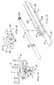
- FIGURE 1 is a longitudinal section through one end of a window sash incorporating part of an espagnolette mechanism and shows the mechanism at the mid point of lock travel with a locking bolt shown in mid adjustment, part of the sash being omitted for the sake of clarity;
- FIGURE 2 is a transverse section along the line 2-2 of Figure 1, through both the window sash and its frame;
- FIGURE 3 is a transverse section along the line 3-3 of Figure 1;
- FIGURE 4 is a transverse section along the line 4-4 of Figure 1, to an enlarged scale;
- FIGURE 5 is an exploded, partial perspective view, to an enlarged scale, of a bolt construction formed of a linking rod showing its internal relationship with a window locking pin.
-
- Referring to Figure 2, a window frame is shows at 8 and a window sash at 10. The
sash 10 has theusual rebate 21, sometimes known as a Euro-groove, into which a linkingrod portion 16 of a drive rod for an espagnolette locking mechanism is located. Traditionally, in known constructions (not shown) the drive rod has been formed with a plurality of longitudinally extending diametral slots through which fixing screws pass, the screws engaging in holes formed in an enlarged area 9 of the base of therebate 21, with the heads of the screws holding a plurality of retaining plates against the cheeks of therebate 21, and thus holding the drive rod in therebate 21. Due to the slots in the rod, it can, however, slide to and fro in the rebate. Such a construction is, however, time consuming to assemble. - Referring now to Figures 1 and 3 of the drawings, there is shown a
drive gear housing 11 supporting an associatedroller cam 12. As can be seen from Figure 3, thedrive gear housing 11 is mounted in thesash 10 to project through the base of therebate 21. Theroller cam 12 has amushroom head 31 which fits into acavity 32 formed in akeep member 33 which is attached by one ormore screws 34 to thewindow frame 8. Thecam 12 is operable via a handle (not shown) which drives aspindle 14. Thespindle 14 drives a gear pinion (not shown) which is connected to anaxial drive device 15. As so far described, the mechanism is of known construction. - The
axial drive device 15 is connected in known or other manner to a generally channel-shaped axial linkingrod 16. In accordance with this invention, therod 16 forms a snap-fit into the sash rebate or Euro-groove 21. - As is best seen in Figures 1, 2 and 5, the axial linking
rod 16 is of generally rectangular cross-section, but each of its sides has ataper 27 so as to diverge towards a top wall. Where thetapers 27 begin on each side wall,recesses 23 are provided, extending along the full length of therod 16. Theserecesses 23 co-operate with longitudinally extendingribs 22 which are formed in known manner on the inner faces of therebate 21. To assemblerod 16 in the sash, it is pushed into therebate 21, until theribs 22 snap into therecesses 23 running along the length of linkingrod 16 and located at the junction of the double tapers. - Also in accordance with a preferred feature of this invention, the linking
rod 16 has acircular groove 50 formed throughout its length in the top wall to receive alocking pin 17 of co-operating circular cross-section. The majority of the surface of thepin 17 is knurled, ribbed, threaded or otherwise roughened as shown at 52, and the end portion ofgroove 50 remote from the end connected to thedrive device 15 is likewise knurled, ribbed, threaded or otherwise roughened as at 51 for frictional engagement with thepin 17 when it is snapped into thegroove 50. This arrangement allows the combined length ofrod 16 and lockingpin 17 to be adjusted at will to suit the dimension of the sash to which it is to be fitted. If thepin 17, and preferably thegroove 50 as well, are threaded, fine length adjustment can be obtained by twisting thepin 17 about its longitudinal axis. It will also be appreciated that the linkingrod 16 could alternatively be twisted about its longitudinal axis to achieve fine length adjustment, provided the appropriate screw thread was provided. - As is best seen in Figure 2, the base 7 of the linking
rod 16 completely fills the mouth ofrebate 21, thus presenting a neat appearance. Therod 16 has a projecting tail 6 at its end remote fromdrive device 15 which assists this function, and which has a rebate 4 on its internal face to accommodate an end of a cover strip 18 (see also Figure 4). - At the corner of the
sash 10, an L-shaped guide member 19 having acircular aperture 20 therein for guiding the free end of thelocking pin 17 is secured to thesash 10 byscrews 190. It should be realised, however, that by suitably modifying themember 19 by providing longitudinal grooves in each side face of each arm thereof, thescrews 190 could be dispensed with and themember 19 could then form a snap fit into therebates 21 of the sash by engaging with theribs 22. As can be seen from Figure 1, thecover strip 18 is located between an end face of theguide member 19 and the axial linkingrod 16, and the rebate 4 is provided to accommodate adjustments in the combined length ofrod 16 andpin 17. As can be seen in Figure 4,cover strip 18 is channel-shaped to accommodate thelocking pin 17 and is provided withlongitudinal recesses 40 for the snap-in engagement of theprojecting ribs 22 provided inrebate 21 ofsash 10. - In use, the
locking pin 17 is snapped into axial linkingrod 16 to provide an espagnolette drive rod of the required length for the particular sash, and this is then snapped intorebate 21 of thesash 10. Several different predetermined lengths of linkingrod 16 can be provided, and length adjustment of the entire assembly is possible by selection of an appropriate length of linkingrod 16 and then assembling it as desired with thelocking pin 17. By providing a screw thread engagement betweenrod 16 andpin 17, finer adjustment can take place by rotation ofpin 17 within therod 16.Coverstrip 18 is then snapped into place between linkingrod 16 and guide member 19 (which can also be snap fitted to the corner of sash 10). - Instead of providing a plurality of different lengths of linking
rod 16, and a fixedlength locking pin 17, a fixed length linking rod may be provided, and a plurality of different lengths of locking pin may be provided. In this alternative, different lengths of cover strip would also be needed. - Operation of the espagnolette mechanism is in the standard manner using the handle to move the
mushroom head 31 into engagement with thecavity 32 of thekeep member 33 and to cause longitudinal movement of linkingrod 16 viadrive device 15. Linkingrod 16 slides within therebate 21 and relative tocoverstrip 18, and the lockingpin 17 which is engaged within roughenedportion 51 of thegroove 50 therefore also slides along a path defined byaperture 20 ofguide member 19 which is located at the corner edge of thesash 10. Engagement of lockingpin 17 into a complementary recess provided inframe 8 enablessash 10 to be secured in relation thereto, thus providing a shoot-bolt mechanism in addition to the latching mechanism provided byroller cam 12. - It will thus be appreciated that the present invention provides a locking system having an espagnolette bolt construction, which can be quickly and easily assembled with a snap fit into an edge of a sash. Furthermore, the length of the bolt construction can be adjusted quickly and easily by selecting a component from a range of different lengths of component, and assembling it with a fixed length further component. The method of assembly is very quick, due to the snap together arrangement.
- It will of course be understood that the present invention has been described above purely by way of example, and modifications of detail can be made within the scope of the invention as defined by the appended claims.
Claims (12)
- A sash formed with a rebate (21) therein extending longitudinally along its length, said sash being provided with an espagnolette locking system for its multi-point locking wherein an espagnolette bolt construction (16,17) is located within said rebate (21) for longitudinal movement therein, and wherein said bolt construction (16,17) locates in the sash (10) by snap fitting engagement within the rebate (21) in the sash (10) characterised in that said bolt construction and the rebate (21) are formed respectively with co-operating grooves (23) and ribs (22), so as to permit both the location of the bolt construction (16,17) with a snap fit of said bolt construction within the rebate (21) and to permit the bolt construction (16,17) to slide lengthwise of the rebate (21) on said ribs (22) after it has been located within the rebate (21).
- A sash according to claim 1, characterised in that a groove (23) is provided in each side wall of the bolt construction to receive with a snap fit a rib (22) provided on each face of the rebate (21) of the sash (10).
- A sash according to claim 1 or 2 wherein the bolt construction comprises a linking rod (16) adapted adjustably to receive a locking pin (17) by means of a snap-in connection.
- A sash according to claim 3, characterised in that the bolt construction is axially adjustable in length so as to permit its installation in window sashes of different dimensions, and wherein the bolt construction comprises a linking rod (16) and a locking pin (17) adapted to be connected together with a snap fit in any one of a plurality of different positions, thereby allowing the length of the interconnected rod (16) and locking pin (17) to be chosen to fit a particular size of sash (10).
- A sash according to claim 4, characterised in that a groove (50) of part circular cross-section is formed in the linking rod (16), one end of the groove being adapted to receive one end of the locking pin (17).
- A sash according to claim 4 or 5 characterised in that said locking pin (17) has a roughened end portion (52) adapted to be located within a complementary roughened portion (51) in said linking rod (16) with a force snap fit, thereby permitting the axial adjustment thereof with respect to said linking rod (16).
- A sash according to claim 6, characterised in that the roughened portion (51 or 52) of the linking rod (16) and/or the locking pin (17) is provided by a screw thread to permit fine length adjustment by rotation of the pin (17) and/or the rod (16) about its longitudinal axis.
- A sash according to any one of claims 4-7, characterised in that said window locking pin (17) is of a fixed standard length and said linking rod is of a length selected according to the dimensions of said sash (10).
- A sash system according to any one of claims 4-7, characterised in that said linking rod (16) is of a fixed standard length and said window locking pin (17) is of a length selected according to the dimensions of said sash (10).
- A sash according to any one of the preceding claims, characterised in that the linking rod (16) is formed with tapered (27) side walls each terminating in a longitudinal groove (23) which allows the linking rod (16) to be forced into the rebate (21) in a frame member (10) of a window sash and to be held therein by means of the ribs (22) on the rebate (21) engaging in said grooves (23), but allows the linking rod (16) to the slide longitudinally along the rebate (21).
- A sash according to any one of claims 1-10 and further comprising two corner guide members (19), said guide members each including an aperture (20) therein to facilitate the alignment of a locking pin (17) during operation of the espagnolette locking system.
- A sash according to claim 12, in which said corner guide members (19) are connected to said sash (10) with a snap-fit.
Applications Claiming Priority (2)
| Application Number | Priority Date | Filing Date | Title |
|---|---|---|---|
| GB9300402 | 1993-01-11 | ||
| GB939300402A GB9300402D0 (en) | 1993-01-11 | 1993-01-11 | Espagnolette window locking system and bolt construction |
Publications (2)
| Publication Number | Publication Date |
|---|---|
| EP0607007A1 EP0607007A1 (en) | 1994-07-20 |
| EP0607007B1 true EP0607007B1 (en) | 1999-04-07 |
Family
ID=10728523
Family Applications (1)
| Application Number | Title | Priority Date | Filing Date |
|---|---|---|---|
| EP94300165A Expired - Lifetime EP0607007B1 (en) | 1993-01-11 | 1994-01-11 | Espagnolette window locking system and bolt construction |
Country Status (4)
| Country | Link |
|---|---|
| US (1) | US5660420A (en) |
| EP (1) | EP0607007B1 (en) |
| DE (1) | DE69417592D1 (en) |
| GB (1) | GB9300402D0 (en) |
Cited By (1)
| Publication number | Priority date | Publication date | Assignee | Title |
|---|---|---|---|---|
| DE102004043973C5 (en) * | 2004-09-11 | 2008-10-09 | Roto Frank Ag | Method for connecting assemblies of a fitting arrangement in a fitting part of a door or window sash |
Families Citing this family (23)
| Publication number | Priority date | Publication date | Assignee | Title |
|---|---|---|---|---|
| GB2298450B (en) * | 1995-03-03 | 1998-04-29 | Securistyle Ltd | A shoot bolt |
| GB2336393A (en) * | 1998-03-24 | 1999-10-20 | Securistyle Ltd | Adjustable connectors for a shootbolt mechanism |
| US6415565B1 (en) * | 2000-04-18 | 2002-07-09 | Vent-Alarm Corporation | Storm rail for sliding door |
| DE10033309B4 (en) * | 2000-07-04 | 2004-05-06 | Brose Fahrzeugteile Gmbh & Co. Kg, Coburg | Motor vehicle door lock |
| BE1014943A3 (en) * | 2001-01-29 | 2004-07-06 | Parys Remi E Van | Seizure of a window and components. |
| US6508087B2 (en) * | 2001-05-29 | 2003-01-21 | Mobile Mini, Inc. | Locking system for containers |
| US7175209B2 (en) * | 2002-02-25 | 2007-02-13 | Intier Automotive Closures Inc. | Clip for holding a release lever of a vehicle latch during shipping |
| US6871451B2 (en) * | 2002-03-27 | 2005-03-29 | Newell Operating Company | Multipoint lock assembly |
| US7404306B2 (en) * | 2004-01-29 | 2008-07-29 | Newell Operating Company | Multi-point door lock and offset extension bolt assembly |
| DE102005049766B4 (en) * | 2005-10-18 | 2010-02-04 | Andreas Stihl Ag & Co. Kg | Hand-held cut-off grinder |
| EP1785563A1 (en) * | 2005-11-14 | 2007-05-16 | ERRETI S.r.l. | Set of fastenings for frames |
| US7841221B2 (en) * | 2006-03-31 | 2010-11-30 | Haworth, Inc. | Lock assembly for a storage cabinet |
| US7946080B2 (en) | 2007-01-29 | 2011-05-24 | Newell Operating Company | Lock assembly |
| US8899635B2 (en) * | 2008-10-03 | 2014-12-02 | Truth Hardware Corporation | Sliding door multipoint mortise lock with shoot bolts |
| FR2938866B1 (en) * | 2008-11-26 | 2013-06-14 | Vachette Sa | ACTUATING SYSTEM FOR A DOOR LEVER |
| US20100270814A1 (en) * | 2009-04-23 | 2010-10-28 | Andre Labarre | Motorized system for latching and unlatching casement windows |
| CN201447937U (en) * | 2009-04-24 | 2010-05-05 | 麦元新 | Multifunctional handle lock device for combined glass door |
| US8550506B2 (en) | 2009-06-30 | 2013-10-08 | Truth Hardware Corporation | Multi-point mortise lock mechanism for swinging door |
| CA2680976A1 (en) * | 2009-09-29 | 2011-03-29 | Assa Abloy Financial Services Ab | Adjustable strike and method of providing an adjustable strike |
| US9624701B2 (en) * | 2010-08-30 | 2017-04-18 | Hoppe Holding Ag | Multi-point lock having a shootbolt with a flat driverail mounted in a narrow groove |
| US9482035B2 (en) | 2014-06-20 | 2016-11-01 | Truth Hardware Corporation | Recessed lock actuating device for sliding doors |
| US11585121B2 (en) * | 2017-10-25 | 2023-02-21 | Endura Products, Llc | Residential entryway door with concealed multipoint lock |
| CN117108140A (en) * | 2019-09-13 | 2023-11-24 | 多玛卡巴美国公司 | Tubular outlet device and method of installation |
Family Cites Families (27)
| Publication number | Priority date | Publication date | Assignee | Title |
|---|---|---|---|---|
| US2886960A (en) * | 1954-09-23 | 1959-05-19 | Chamberlin Company Of America | Emergency releasable locking means |
| US2914936A (en) * | 1956-03-29 | 1959-12-01 | Standard Oil Co | Sealing joint for architectural porcelain enameled panels |
| US3068939A (en) * | 1959-10-20 | 1962-12-18 | Nat Distillers Chem Corp | Frame for mounting plastic film |
| DE1908479A1 (en) * | 1969-02-20 | 1970-09-10 | Frank Gmbh Wilh | Fuellstueck to cover a concealed drive rod |
| DE2040632A1 (en) * | 1970-08-17 | 1972-02-24 | Weber & Co | Overlay furniture lock with counter-rotating bolt bars |
| DE2311990A1 (en) * | 1973-03-10 | 1974-09-12 | Frank Gmbh Wilh | DEVICE FOR THE LENGTH ADJUSTABLE CONNECTION OF PUSH RODS AND / OR PUSH LINKS OF A FITTING FOR A WINDOW, A DOOR OR. DGL |
| DE2429893C2 (en) * | 1974-06-21 | 1982-12-09 | Wilh. Frank Gmbh, 7022 Leinfelden-Echterdingen | Closure for windows, doors or the like. |
| DE2720862A1 (en) * | 1977-05-10 | 1978-11-23 | Simon Karl Metallwaren | Lock housing with snap fit cover plate - has side walls with flexible connectors for snap fit |
| DE2920581C2 (en) * | 1979-05-21 | 1983-07-21 | Siegenia-Frank Kg, 5900 Siegen | Additional locking, in particular central locking, for windows, doors or the like. |
| ES480950A1 (en) * | 1979-05-25 | 1979-08-01 | Duart Bonet Jose | Adjustable multiple bolt locking system |
| US4368905A (en) * | 1980-07-21 | 1983-01-18 | Adams Rite Manufacturing Co. | Exit door locking mechanism having multiple bolts |
| DE8324586U1 (en) * | 1983-08-26 | 1983-12-08 | Schaumburg-Lippische Baubeschlag-Fabrik W. Hautau GmbH, 3061 Helpsen | Longitudinally adjustable rod coupling on connecting rod fittings for windows, doors or the like. |
| US4617775A (en) * | 1984-09-04 | 1986-10-21 | John Padrun | Extensible reinforcing bar assembly and clip |
| JPH0134962Y2 (en) * | 1985-03-15 | 1989-10-25 | ||
| DE3609584A1 (en) * | 1986-03-21 | 1987-10-08 | Heinrich Saelzer | DEVICE FOR LOCKING A BLADE FRAME |
| FR2600127B1 (en) * | 1986-06-17 | 1988-12-02 | Peugeot | DEVICE FOR CONNECTING AN END OF A ROD TO A PART ALLOWING A LARGE ADJUSTMENT LATITUDE IN THE LONGITUDINAL DIRECTION OF THE ROD |
| US4733988A (en) * | 1986-10-07 | 1988-03-29 | Kelly Clifford G | Clamp for a sheet |
| DE3710056C3 (en) * | 1987-03-27 | 1997-10-09 | Siegenia Frank Kg | Sash frame for a window or a door, which is composed of metal or plastic profiles |
| US4907908A (en) * | 1987-10-28 | 1990-03-13 | Siegenia-Frank Kg | Adjustable rod joint |
| US5371991A (en) * | 1987-12-07 | 1994-12-13 | Bechtel; Richard | Re-bar clamp assembly |
| GB2216170A (en) * | 1988-02-27 | 1989-10-04 | Gkn Crompton | Window fastening system |
| FR2632343B1 (en) * | 1988-06-02 | 1990-08-17 | Ferco Int Usine Ferrures | LOCKING FITTING FOR SLIDING OPENING |
| GB8903434D0 (en) * | 1989-02-15 | 1989-04-05 | Daw Products Limited | Cross bolt |
| DE9001276U1 (en) * | 1990-02-05 | 1991-06-27 | Ferco International Usine De Ferrures De Batiment, Sarrebourg, Fr | |
| DE9001277U1 (en) * | 1990-02-05 | 1991-06-20 | Ferco International Usine De Ferrures De Batiment, Sarrebourg, Fr | |
| US5042852A (en) * | 1990-10-03 | 1991-08-27 | Von Duprin, Inc. | Latch and rod guard assembly |
| US5183302A (en) * | 1991-08-06 | 1993-02-02 | General Motors Corporation | Door handle housing attachment for vehicle door |
-
1993
- 1993-01-11 GB GB939300402A patent/GB9300402D0/en active Pending
-
1994
- 1994-01-10 US US08/179,503 patent/US5660420A/en not_active Expired - Lifetime
- 1994-01-11 EP EP94300165A patent/EP0607007B1/en not_active Expired - Lifetime
- 1994-01-11 DE DE69417592T patent/DE69417592D1/en not_active Expired - Lifetime
Cited By (1)
| Publication number | Priority date | Publication date | Assignee | Title |
|---|---|---|---|---|
| DE102004043973C5 (en) * | 2004-09-11 | 2008-10-09 | Roto Frank Ag | Method for connecting assemblies of a fitting arrangement in a fitting part of a door or window sash |
Also Published As
| Publication number | Publication date |
|---|---|
| US5660420A (en) | 1997-08-26 |
| DE69417592D1 (en) | 1999-05-12 |
| GB9300402D0 (en) | 1993-03-03 |
| EP0607007A1 (en) | 1994-07-20 |
Similar Documents
| Publication | Publication Date | Title |
|---|---|---|
| EP0607007B1 (en) | Espagnolette window locking system and bolt construction | |
| US6651389B2 (en) | Casement window with improved tie bar guide and striker | |
| EP0996801B1 (en) | Fastening of end caps on housings comprised of profile sections | |
| US5409278A (en) | Handle assembly | |
| KR0185243B1 (en) | Locking mechanism for widows or doors | |
| EP0756661A1 (en) | Latch with variable lock insert | |
| CZ2000487A3 (en) | Supporting means for shielding device | |
| GB1575900A (en) | Adjustable keeper plate assembly for use with crescet sashfastener | |
| JPH0771161A (en) | Connecting-rod driving device | |
| CN110036165B (en) | Window and door opening and closing mechanism | |
| CA1229358A (en) | Extended latch tube assembly | |
| EP1747334A1 (en) | Recessed grip | |
| CN108316767B (en) | Driver and door and window structure | |
| EP0389448B1 (en) | Bolt mechanism for sliding doors, windows and related items | |
| EP0440987B2 (en) | Espagnolette fastening | |
| GB2554725B (en) | Shoot bolt guide device | |
| JPH0360994B2 (en) | ||
| DE19802146A1 (en) | Device for locking a cabinet door | |
| DE602004004982T2 (en) | Corner guide for doors and windows | |
| EP1621707A1 (en) | An assembly of elements comprising a control device for door and window frame handles | |
| GB2323122A (en) | Double shoot bolt fastening | |
| GB2398830A (en) | Adjustable shoot bolt arms lockable by operation of driving mechanism | |
| GB2336393A (en) | Adjustable connectors for a shootbolt mechanism | |
| GB2260779A (en) | Espagnolette bar guide | |
| JPH0144872B2 (en) |
Legal Events
| Date | Code | Title | Description |
|---|---|---|---|
| PUAI | Public reference made under article 153(3) epc to a published international application that has entered the european phase |
Free format text: ORIGINAL CODE: 0009012 |
|
| AK | Designated contracting states |
Kind code of ref document: A1 Designated state(s): BE DE ES FR GB IT |
|
| 17P | Request for examination filed |
Effective date: 19950109 |
|
| 17Q | First examination report despatched |
Effective date: 19951208 |
|
| GRAG | Despatch of communication of intention to grant |
Free format text: ORIGINAL CODE: EPIDOS AGRA |
|
| GRAG | Despatch of communication of intention to grant |
Free format text: ORIGINAL CODE: EPIDOS AGRA |
|
| GRAG | Despatch of communication of intention to grant |
Free format text: ORIGINAL CODE: EPIDOS AGRA |
|
| GRAH | Despatch of communication of intention to grant a patent |
Free format text: ORIGINAL CODE: EPIDOS IGRA |
|
| GRAH | Despatch of communication of intention to grant a patent |
Free format text: ORIGINAL CODE: EPIDOS IGRA |
|
| GRAA | (expected) grant |
Free format text: ORIGINAL CODE: 0009210 |
|
| STAA | Information on the status of an ep patent application or granted ep patent |
Free format text: STATUS: THE PATENT HAS BEEN GRANTED |
|
| RAP1 | Party data changed (applicant data changed or rights of an application transferred) |
Owner name: SCHLEGEL SYSTEMS, INC. |
|
| AK | Designated contracting states |
Kind code of ref document: B1 Designated state(s): BE DE ES FR GB IT |
|
| PG25 | Lapsed in a contracting state [announced via postgrant information from national office to epo] |
Ref country code: IT Free format text: LAPSE BECAUSE OF FAILURE TO SUBMIT A TRANSLATION OF THE DESCRIPTION OR TO PAY THE FEE WITHIN THE PRE;WARNING: LAPSES OF ITALIAN PATENTS WITH EFFECTIVE DATE BEFORE 2007 MAY HAVE OCCURRED AT ANY TIME BEFORE 2007. THE CORRECT EFFECTIVE DATE MAY BE DIFFERENT FROM THE ONE RECORDED.SCRIBED TIME-LIMIT Effective date: 19990407 Ref country code: ES Free format text: THE PATENT HAS BEEN ANNULLED BY A DECISION OF A NATIONAL AUTHORITY Effective date: 19990407 Ref country code: BE Free format text: LAPSE BECAUSE OF FAILURE TO SUBMIT A TRANSLATION OF THE DESCRIPTION OR TO PAY THE FEE WITHIN THE PRESCRIBED TIME-LIMIT Effective date: 19990407 |
|
| REF | Corresponds to: |
Ref document number: 69417592 Country of ref document: DE Date of ref document: 19990512 |
|
| PG25 | Lapsed in a contracting state [announced via postgrant information from national office to epo] |
Ref country code: DE Free format text: LAPSE BECAUSE OF FAILURE TO SUBMIT A TRANSLATION OF THE DESCRIPTION OR TO PAY THE FEE WITHIN THE PRESCRIBED TIME-LIMIT Effective date: 19990708 |
|
| EN | Fr: translation not filed | ||
| REG | Reference to a national code |
Ref country code: FR Ref legal event code: RN |
|
| PLBE | No opposition filed within time limit |
Free format text: ORIGINAL CODE: 0009261 |
|
| REG | Reference to a national code |
Ref country code: FR Ref legal event code: FC |
|
| 26N | No opposition filed | ||
| ET | Fr: translation filed | ||
| REG | Reference to a national code |
Ref country code: GB Ref legal event code: IF02 |
|
| PGFP | Annual fee paid to national office [announced via postgrant information from national office to epo] |
Ref country code: GB Payment date: 20080130 Year of fee payment: 15 |
|
| PGFP | Annual fee paid to national office [announced via postgrant information from national office to epo] |
Ref country code: FR Payment date: 20080131 Year of fee payment: 15 |
|
| GBPC | Gb: european patent ceased through non-payment of renewal fee |
Effective date: 20090111 |
|
| REG | Reference to a national code |
Ref country code: FR Ref legal event code: ST Effective date: 20091030 |
|
| PG25 | Lapsed in a contracting state [announced via postgrant information from national office to epo] |
Ref country code: GB Free format text: LAPSE BECAUSE OF NON-PAYMENT OF DUE FEES Effective date: 20090111 |
|
| PG25 | Lapsed in a contracting state [announced via postgrant information from national office to epo] |
Ref country code: FR Free format text: LAPSE BECAUSE OF NON-PAYMENT OF DUE FEES Effective date: 20090202 |