EP0606071A1 - Piège à particules - Google Patents
Piège à particules Download PDFInfo
- Publication number
- EP0606071A1 EP0606071A1 EP94100067A EP94100067A EP0606071A1 EP 0606071 A1 EP0606071 A1 EP 0606071A1 EP 94100067 A EP94100067 A EP 94100067A EP 94100067 A EP94100067 A EP 94100067A EP 0606071 A1 EP0606071 A1 EP 0606071A1
- Authority
- EP
- European Patent Office
- Prior art keywords
- pores
- filter element
- particulate trap
- filter
- metal
- Prior art date
- Legal status (The legal status is an assumption and is not a legal conclusion. Google has not performed a legal analysis and makes no representation as to the accuracy of the status listed.)
- Granted
Links
Images


Classifications
-
- F—MECHANICAL ENGINEERING; LIGHTING; HEATING; WEAPONS; BLASTING
- F01—MACHINES OR ENGINES IN GENERAL; ENGINE PLANTS IN GENERAL; STEAM ENGINES
- F01N—GAS-FLOW SILENCERS OR EXHAUST APPARATUS FOR MACHINES OR ENGINES IN GENERAL; GAS-FLOW SILENCERS OR EXHAUST APPARATUS FOR INTERNAL COMBUSTION ENGINES
- F01N3/00—Exhaust or silencing apparatus having means for purifying, rendering innocuous, or otherwise treating exhaust
- F01N3/02—Exhaust or silencing apparatus having means for purifying, rendering innocuous, or otherwise treating exhaust for cooling, or for removing solid constituents of, exhaust
- F01N3/021—Exhaust or silencing apparatus having means for purifying, rendering innocuous, or otherwise treating exhaust for cooling, or for removing solid constituents of, exhaust by means of filters
- F01N3/023—Exhaust or silencing apparatus having means for purifying, rendering innocuous, or otherwise treating exhaust for cooling, or for removing solid constituents of, exhaust by means of filters using means for regenerating the filters, e.g. by burning trapped particles
- F01N3/027—Exhaust or silencing apparatus having means for purifying, rendering innocuous, or otherwise treating exhaust for cooling, or for removing solid constituents of, exhaust by means of filters using means for regenerating the filters, e.g. by burning trapped particles using electric or magnetic heating means
-
- B—PERFORMING OPERATIONS; TRANSPORTING
- B01—PHYSICAL OR CHEMICAL PROCESSES OR APPARATUS IN GENERAL
- B01D—SEPARATION
- B01D39/00—Filtering material for liquid or gaseous fluids
- B01D39/14—Other self-supporting filtering material ; Other filtering material
- B01D39/20—Other self-supporting filtering material ; Other filtering material of inorganic material, e.g. asbestos paper, metallic filtering material of non-woven wires
- B01D39/2027—Metallic material
- B01D39/2041—Metallic material the material being filamentary or fibrous
-
- B—PERFORMING OPERATIONS; TRANSPORTING
- B01—PHYSICAL OR CHEMICAL PROCESSES OR APPARATUS IN GENERAL
- B01D—SEPARATION
- B01D39/00—Filtering material for liquid or gaseous fluids
- B01D39/14—Other self-supporting filtering material ; Other filtering material
- B01D39/20—Other self-supporting filtering material ; Other filtering material of inorganic material, e.g. asbestos paper, metallic filtering material of non-woven wires
- B01D39/2027—Metallic material
- B01D39/2051—Metallic foam
-
- F—MECHANICAL ENGINEERING; LIGHTING; HEATING; WEAPONS; BLASTING
- F01—MACHINES OR ENGINES IN GENERAL; ENGINE PLANTS IN GENERAL; STEAM ENGINES
- F01N—GAS-FLOW SILENCERS OR EXHAUST APPARATUS FOR MACHINES OR ENGINES IN GENERAL; GAS-FLOW SILENCERS OR EXHAUST APPARATUS FOR INTERNAL COMBUSTION ENGINES
- F01N3/00—Exhaust or silencing apparatus having means for purifying, rendering innocuous, or otherwise treating exhaust
- F01N3/02—Exhaust or silencing apparatus having means for purifying, rendering innocuous, or otherwise treating exhaust for cooling, or for removing solid constituents of, exhaust
- F01N3/021—Exhaust or silencing apparatus having means for purifying, rendering innocuous, or otherwise treating exhaust for cooling, or for removing solid constituents of, exhaust by means of filters
- F01N3/022—Exhaust or silencing apparatus having means for purifying, rendering innocuous, or otherwise treating exhaust for cooling, or for removing solid constituents of, exhaust by means of filters characterised by specially adapted filtering structure, e.g. honeycomb, mesh or fibrous
- F01N3/0222—Exhaust or silencing apparatus having means for purifying, rendering innocuous, or otherwise treating exhaust for cooling, or for removing solid constituents of, exhaust by means of filters characterised by specially adapted filtering structure, e.g. honeycomb, mesh or fibrous the structure being monolithic, e.g. honeycombs
-
- F—MECHANICAL ENGINEERING; LIGHTING; HEATING; WEAPONS; BLASTING
- F01—MACHINES OR ENGINES IN GENERAL; ENGINE PLANTS IN GENERAL; STEAM ENGINES
- F01N—GAS-FLOW SILENCERS OR EXHAUST APPARATUS FOR MACHINES OR ENGINES IN GENERAL; GAS-FLOW SILENCERS OR EXHAUST APPARATUS FOR INTERNAL COMBUSTION ENGINES
- F01N3/00—Exhaust or silencing apparatus having means for purifying, rendering innocuous, or otherwise treating exhaust
- F01N3/02—Exhaust or silencing apparatus having means for purifying, rendering innocuous, or otherwise treating exhaust for cooling, or for removing solid constituents of, exhaust
- F01N3/021—Exhaust or silencing apparatus having means for purifying, rendering innocuous, or otherwise treating exhaust for cooling, or for removing solid constituents of, exhaust by means of filters
- F01N3/022—Exhaust or silencing apparatus having means for purifying, rendering innocuous, or otherwise treating exhaust for cooling, or for removing solid constituents of, exhaust by means of filters characterised by specially adapted filtering structure, e.g. honeycomb, mesh or fibrous
- F01N3/0226—Exhaust or silencing apparatus having means for purifying, rendering innocuous, or otherwise treating exhaust for cooling, or for removing solid constituents of, exhaust by means of filters characterised by specially adapted filtering structure, e.g. honeycomb, mesh or fibrous the structure being fibrous
-
- F—MECHANICAL ENGINEERING; LIGHTING; HEATING; WEAPONS; BLASTING
- F01—MACHINES OR ENGINES IN GENERAL; ENGINE PLANTS IN GENERAL; STEAM ENGINES
- F01N—GAS-FLOW SILENCERS OR EXHAUST APPARATUS FOR MACHINES OR ENGINES IN GENERAL; GAS-FLOW SILENCERS OR EXHAUST APPARATUS FOR INTERNAL COMBUSTION ENGINES
- F01N2330/00—Structure of catalyst support or particle filter
- F01N2330/02—Metallic plates or honeycombs, e.g. superposed or rolled-up corrugated or otherwise deformed sheet metal
-
- F—MECHANICAL ENGINEERING; LIGHTING; HEATING; WEAPONS; BLASTING
- F01—MACHINES OR ENGINES IN GENERAL; ENGINE PLANTS IN GENERAL; STEAM ENGINES
- F01N—GAS-FLOW SILENCERS OR EXHAUST APPARATUS FOR MACHINES OR ENGINES IN GENERAL; GAS-FLOW SILENCERS OR EXHAUST APPARATUS FOR INTERNAL COMBUSTION ENGINES
- F01N2470/00—Structure or shape of gas passages, pipes or tubes
- F01N2470/24—Concentric tubes or tubes being concentric to housing, e.g. telescopically assembled
-
- F—MECHANICAL ENGINEERING; LIGHTING; HEATING; WEAPONS; BLASTING
- F02—COMBUSTION ENGINES; HOT-GAS OR COMBUSTION-PRODUCT ENGINE PLANTS
- F02B—INTERNAL-COMBUSTION PISTON ENGINES; COMBUSTION ENGINES IN GENERAL
- F02B3/00—Engines characterised by air compression and subsequent fuel addition
- F02B3/06—Engines characterised by air compression and subsequent fuel addition with compression ignition
-
- Y—GENERAL TAGGING OF NEW TECHNOLOGICAL DEVELOPMENTS; GENERAL TAGGING OF CROSS-SECTIONAL TECHNOLOGIES SPANNING OVER SEVERAL SECTIONS OF THE IPC; TECHNICAL SUBJECTS COVERED BY FORMER USPC CROSS-REFERENCE ART COLLECTIONS [XRACs] AND DIGESTS
- Y10—TECHNICAL SUBJECTS COVERED BY FORMER USPC
- Y10S—TECHNICAL SUBJECTS COVERED BY FORMER USPC CROSS-REFERENCE ART COLLECTIONS [XRACs] AND DIGESTS
- Y10S55/00—Gas separation
- Y10S55/10—Residue burned
-
- Y—GENERAL TAGGING OF NEW TECHNOLOGICAL DEVELOPMENTS; GENERAL TAGGING OF CROSS-SECTIONAL TECHNOLOGIES SPANNING OVER SEVERAL SECTIONS OF THE IPC; TECHNICAL SUBJECTS COVERED BY FORMER USPC CROSS-REFERENCE ART COLLECTIONS [XRACs] AND DIGESTS
- Y10—TECHNICAL SUBJECTS COVERED BY FORMER USPC
- Y10S—TECHNICAL SUBJECTS COVERED BY FORMER USPC CROSS-REFERENCE ART COLLECTIONS [XRACs] AND DIGESTS
- Y10S55/00—Gas separation
- Y10S55/30—Exhaust treatment
Definitions
- This invention relates to a particulate trap for collecting and removing particulates such as carbon contained in exhaust gas discharged from a diesel engine.
- Exhaust gas discharged from cars is a major cause of air pollution. It is very important to develop techniques for removing harmful components contained in the exhaust gas. It is especially important to develop techniques for removing particulates in the exhaust gas discharged from diesel engines, which contain NOx and carbon.
- a particulate trap for collecting particulates contained in the exhaust gas has to meet the following requirements in view of the conditions of use:
- the exhaust gas has to be capable of collecting particulates with such high efficiency that the exhaust gas is cleaned sufficiently.
- the amount of particulates contained in the exhaust gas depends on the displacement of the diesel engine and the load applied. It is generally considered that such a trap has to be capable of collecting at least 60% of the particulates in the exhaust gas.
- such a trap must not unduly prevent the flow of exhaust gas. As the amount of the particulates collected by the trap increases, the pressure drop increases gradually. If such pressure drop is too high, an undesirable back pressure will act on the engine. It is considered necessary to keep such pressure drop below 30 KPa. For this purpose, it is necessary to use a particulate trap which is low not only in initial pressure drop but also keeps the pressure drop low even after it has collected particulates.
- such a trap has to permit regeneration without requiring much energy.
- the trap has to have means for burning the collected particulates to regenerate it.
- One conceivable device for burning particulates is a light oil burner. But considering the safety and ease of control, an electric heater is considered more promising. But the trap has to be regenerated without consuming too much electric power because the capacity of a battery on a car is limited.
- a wall-flow type honeycomb-shaped porous member made of cordierite ceramic is considered most practical as the filter element material in the particulate trap. But with this type of filter, particulates tend to collect in a limited area. Further, due to low heat conductivity of cordierite ceramic, heat spots tend to develop when burning particulates. Thus, the filter may melt or develop cracks due to thermal stress. Such a filter is therefore not reliable enough.
- Such traps have a structural problem in that their filtration area through which exhaust gas can pass is small compared with a cordierite ceramic filter. If the filter is designed so as to show increased particulate collection efficiency, the particulates will be collected only on the surface of the filter, thus clogging it. The clogged filter will sharply increase the pressure drop. Thus, the life of such a filter is very short.
- An object of the present invention is to provide a particulate trap which solves these problems.
- an electric heater for burning particulates is interposed between the opposed surfaces of the filter elements.
- the distance between the heater and the filter element should preferably be 20 mm or less.
- the filter element from at least two different kinds of filter materials whose pore diameters are different from one another so that the material having large-diameter pores is arranged nearer to the exhaust gas inlet side than is the material having small-diameter pores. This makes it possible to prolong the pressure drop life of the filter element, reduce its weight and heat capacity and thus to regenerate it in a shorter period of time.
- the filter element should preferably be made of a three-dimensional mesh-like porous metal member, an unwoven metal web or a three-dimensional mesh-like porous metal member having its pores stuffed with ceramics or metal to reduce their diameter.
- the above-mentioned filter materials i.e. the three-dimensional mesh-like porous metal member (A), an unwoven metal web (B), and the three-dimensional mesh-like porous metal member having its pores stuffed with ceramics or metal to reduce their diameter (C), are used in combination so that the material having larger-diameter pores is arranged nearer to the exhaust gas inlet side than is the material having smaller-diameter pores.
- They can be combined in the following manner:
- the electric heater consumes less electric power for regeneration.
- the filter element is arranged so that its pores nearer to the exhaust gas inlet side have larger diameters than those nearer to the outlet side, particulates can be collected uniformly over the entire area of the filter in the direction of thickness.
- the filter is thus less likely to clog. This leads to a prolonged pressure drop life and a lighter filter weight and thus a shorter regeneration time. Shorter regeneration time means lesser electric power consumption.
- the particulate trap of the present invention has its electric heater for burning collected particulates interposed between the opposed surfaces of the filter elements so as not to interfere with the flow of exhaust gas.
- the collected particulates will not increase the pressure drop of the filter, so that its particulate collection capacity is kept high for a prolonged period of time.
- the particulates can be burned efficiently by the electric heater with lesser electric power consumption.
- This invention is therefore especially suitable for application to diesel engine cars for which there is a growing demand for measures to clean their exhaust gas and the battery capacity is limited.
- Fig. 1 shows an apparatus for experiment. It comprises a 3400 cc, four-cylinder, direct-injection diesel engine car, a chassis dynamometer and a dilution tunnel.
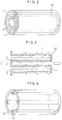
- Fig. 2 shows the first embodiment of the particulate trap for use in a diesel engine according to the present invention. It comprises cylindrical filters 1 and 2 having different diameters and nested together and an electric heater 3 disposed therebetween. This filter element 10 with a built-in heater is mounted in a case 11 shown in Fig. 1.
- Fig. 3 shows a sectional view of the filter element 10 shown in Fig. 2.
- Exhaust gas is introduced into between the filters 1, 2. Part of the gas flows through the filter 1 to its outside and the remaining part flows through the filter 2 into its inside.
- the gas inlet side and the opposite end face are sealed by iron plates 4 through gaskets.
- the filters in this embodiment were cylindrical members formed by adding Cr to a Ni-based three-dimensional mesh-like porous member (trade name: Cermet) made by Sumitomo Electric Industries, Ltd.
- the heater 3 comprises a cylindrical member made of punching metal and a sheath heater 4 mm in diameter wound around the cylindrical member.
- specimen B For comparison purposes, experiments were also done on a trap having a cylindrical structure (specimen B) shown in Fig. 6, which is employed in ordinary metal traps and ceramic fiber traps.
- the specimen B comprises seven filter elements mounted in a case, each element comprising a filter 12 made of the same material as the specimen A and four sheath heaters 13 arranged at the pitch of 90°.
- Table 1 shows the specifications of the specimens A and B such as dimensions.
- Table 1 Specimen Cerment No. Thickness of material (cermet) No. of turns Material Size No. of filter elements Packing density A #7 0.9 mm 4 NiCr Filter 1: ⁇ 48 ⁇ 39 ⁇ 190L 7 21.1 % Filter 2: ⁇ 29 ⁇ 27 ⁇ 190L B #7 0.9 mm 4 NiCr ⁇ 48 ⁇ 39 ⁇ 190L 7 21.2 %
- A according to the present invention B: for comparison
- the item numbers in the table show the number of cells (or pores) in a unit area. #7 has 50 - 70 cells per inch.
- the results of experiments are shown in Figs. 7 and 8.
- the particulate collection capacity of each specimen is represented in terms of the pressure drop and the collection efficiency with respect to accumulated PM amount (amount of particulates).
- the regeneration is shown in terms of the recovery rate of the pressure drop when the heater power is applied.
- a punching metal was heated by the sheath heater to uniformly heat the entire surfaces of the filters by the radiation heat from the punching metal.
- the heating medium is not limited to punching metal. It may be expanded metal or an ordinary wire net or porous metal.
- a plate-shaped heater in order to heat the filters uniformly. But this is not an essential requirement.
- a rod-shaped sheath heater may be interposed between the opposed surfaces of the filters.
- the heater 3 may be in contact with one or both of the opposed surfaces of the filters. Point is that the heater is disposed between the opposed surfaces in such a way as not to interfere with the flow of exhaust gas.
- the particulate trap of the second embodiment has the same structure as the one shown in Fig. 2 (its section is the same as shown in Fig. 3) but differs therefrom in that the filters are cylindrical members formed from unwoven web of metal fiber.
- the unwoven metal web is of an Fe-Cr-Al alloy but may be made of any other material.
- the heater is formed by stamping a thin plate of inconel and shaping it into a tube after adjusting its resistance. It is heated by directly supplying electricity thereto.
- the heater may be made of a material other than inconel.
- a trap having a cylindrical structure shown in Fig. 6, which is employed in ordinary metal traps and ceramic fiber traps.
- This comparative specimen D comprises seven filter elements mounted in a case, each element comprising a cylindrical filter 12 made of unwoven metal web and four rod-shaped heaters 13 mounted in the filter as shown.
- Table 2 shows the specifications of the specimens C and D such as dimensions.
- Table 2 Specimen Fiber diameter of metal unwoven web Thickness of material (metal unwoven web) No. of turns Material Size No. of filter elements Packing density C 30 ⁇ m 0.5 mm 2 FeCrAl Filter 1: ⁇ 62 ⁇ 60 ⁇ 190L 7 20.0 % Filter 2: ⁇ 50 ⁇ 48 ⁇ 190L D 30 ⁇ m 0.5 mm 2 FeCrAl ⁇ 57 ⁇ 55 ⁇ 190L 7 20.0 %
- D for comparison
- the results of experiments are shown in Figs. 10 - 12.
- the particulate collection capacity of each specimen is represented in terms of the pressure drop and collection efficiency with respect to accumulated PM amount.
- the regeneration capacity is shown in terms of the recovery rate of the pressure drop when the heater power is applied.
- the experimental apparatus used here is also the same as the apparatus shown in Fig. 1.
- the specimen of the third embodiment is a filter element 10 shown in Fig. 4 (its section is shown in Fig. 5).
- This filter element comprises a web of filter plate 21 which is folded over many times to provide a plurality of layers and a plurality of plate heaters 23 disposed between the layers.
- exhaust gas is introduced into the gaps defined between the adjacent layers of the filter plate 21.
- its sides are sealed by iron plates (not shown).
- the filter element used as the particulate trap of the third embodiment is made of unwoven web of metal fiber whose diameter decreases gradually from its exhaust gas inlet toward outlet so that the pores nearer to the inlet have larger diameters than those nearer to the outlet.
- the unwoven metal web is made of a Ni-Cr-Al alloy in the embodiment but may be made of any other material.
- the plate-shaped heaters 23 are formed by blanking an inconel thin plate and adjusting its resistance.
- the heaters may be made of a material other than inconel. They may comprise a plate of punching metal and heater wires attached thereto.
- the filter element of this embodiment was mounted in a trap case to form the particulate trap of the present invention (specimen E). Its performance was evaluated.
- specimen F For comparison purposes, a conventional trap having a cylindrical configuration as shown in Fig. 6 (specimen F) was also tested.
- the specimen F comprises a cylindrical filter made of the same material as the specimen E and four rod-shaped heaters mounted thereto.
- Table 3 shows data on the specimens E and F such as dimensions.
- Table 3 Specimen Fiber diameter of metal unwoven web Thickness of material (metal unwoven web) Material Shape of filter Size No. of filter elements Packing density E 40 ⁇ m at exhaust inlet Total 1.0 mm NiCrAl Parallel plane plate Filter contour: W130 ⁇ H130 ⁇ D190 1 20.0 % 20 ⁇ m at exhaust outlet F 40 ⁇ m at exhaust inlet Total 1.0 mm NiCrAl Cylindrical ⁇ 57 ⁇ 55 ⁇ 190L 7 20.0 % 20 ⁇ m at exhaust outlet E: according to the present invention F: for comparison
- the results of experiments are shown in Figs. 13 - 15.
- the particulate collection capacity of each specimen is represented in terms of the pressure drop and collection efficiency with respect to accumulated PM amount.
- the regeneration capacity is shown in terms of the pressure recovery rate when the heater power is applied.
Applications Claiming Priority (4)
| Application Number | Priority Date | Filing Date | Title |
|---|---|---|---|
| JP735/93 | 1993-01-06 | ||
| JP73593 | 1993-01-06 | ||
| JP290792/93 | 1993-11-19 | ||
| JP5290792A JPH06257422A (ja) | 1993-01-06 | 1993-11-19 | ディーゼルエンジン用パティキュレートトラップ |
Publications (2)
| Publication Number | Publication Date |
|---|---|
| EP0606071A1 true EP0606071A1 (fr) | 1994-07-13 |
| EP0606071B1 EP0606071B1 (fr) | 1997-04-09 |
Family
ID=26333781
Family Applications (1)
| Application Number | Title | Priority Date | Filing Date |
|---|---|---|---|
| EP94100067A Expired - Lifetime EP0606071B1 (fr) | 1993-01-06 | 1994-01-04 | Piège à particules |
Country Status (4)
| Country | Link |
|---|---|
| US (1) | US6024927A (fr) |
| EP (1) | EP0606071B1 (fr) |
| JP (1) | JPH06257422A (fr) |
| DE (1) | DE69402437T2 (fr) |
Cited By (10)
| Publication number | Priority date | Publication date | Assignee | Title |
|---|---|---|---|---|
| EP0707139A1 (fr) * | 1994-10-13 | 1996-04-17 | Sumitomo Electric Industries, Inc. | Filtre à particules |
| EP0745759A2 (fr) * | 1995-05-30 | 1996-12-04 | Sumitomo Electric Industries, Inc. | Piège à particules pour un moteur diesel |
| EP0747579A2 (fr) * | 1995-05-30 | 1996-12-11 | Sumitomo Electric Industries, Limited | Piège des particules pour un moteur diesel |
| EP0766993A2 (fr) * | 1995-10-02 | 1997-04-09 | Toyota Jidosha Kabushiki Kaisha | Filtre pour purifier le gaz d'échappement |
| EP0838578A1 (fr) * | 1996-10-22 | 1998-04-29 | Sumitomo Electric Industries, Ltd. | Piège à particules et élément chauffant |
| EP0849444A2 (fr) * | 1996-12-18 | 1998-06-24 | Sumitomo Electric Industries, Ltd. | Piège des particules pour un moteur diesel |
| US5908480A (en) * | 1996-03-29 | 1999-06-01 | Sumitomo Electric Industries, Ltd. | Particulate trap for diesel engine |
| US6120583A (en) * | 1997-12-19 | 2000-09-19 | Sumitomo Electric Industries, Ltd. | Exhaust gas purifier and operating method thereof |
| CN1101892C (zh) * | 1997-02-04 | 2003-02-19 | 发射技术有限公司 | 耐热和可再生的具有流通路径的过滤体 |
| EP1898060A1 (fr) * | 2006-09-07 | 2008-03-12 | Nissin Electric Co., Ltd. | Appareil pour l'élimination de particules |
Families Citing this family (16)
| Publication number | Priority date | Publication date | Assignee | Title |
|---|---|---|---|---|
| JPH08229330A (ja) * | 1995-02-28 | 1996-09-10 | Sumitomo Electric Ind Ltd | ディーゼルエンジン用パティキュレートトラップ |
| JPH10317945A (ja) * | 1997-05-21 | 1998-12-02 | Sumitomo Electric Ind Ltd | 排気ガス浄化装置 |
| JP3462750B2 (ja) | 1998-05-14 | 2003-11-05 | 住友電気工業株式会社 | ディーゼルエンジン用パティキュレートトラップ |
| JP2001073742A (ja) | 1999-06-29 | 2001-03-21 | Sumitomo Electric Ind Ltd | ディーゼルエンジン用パティキュレートトラップ |
| DE10003816A1 (de) * | 2000-01-28 | 2001-08-02 | Opel Adam Ag | Regenerierbarer Partikelfilter zum Entfernen von Rußpartikeln aus Abgasen |
| DE10029978A1 (de) | 2000-06-26 | 2002-01-10 | Zeuna Staerker Kg | Vorrichtung zur Nachbehandlung von Dieselabgasen |
| DE10105233A1 (de) * | 2001-02-02 | 2002-08-29 | Zeuna Staerker Kg | Vorrichtung zur Nachbehandlung von Dieselabgasen |
| JP2002364334A (ja) * | 2001-06-06 | 2002-12-18 | Mitsui Eng & Shipbuild Co Ltd | 粒子状物質除去フィルタ |
| DE10156696A1 (de) * | 2001-11-17 | 2003-06-05 | Wirth Gabriele | Reinigungsgerät |
| WO2005005797A2 (fr) * | 2003-06-12 | 2005-01-20 | Donaldson Company, Inc. | Procede d'apport de carburant dans un ecoulement transitoire d'un systeme d'echappement |
| US7455709B2 (en) | 2003-07-15 | 2008-11-25 | Ibiden Co., Ltd. | Honeycomb structural body |
| US20060101810A1 (en) * | 2004-11-15 | 2006-05-18 | Angelo Theodore G | System for dispensing fuel into an exhaust system of a diesel engine |
| JP2009011921A (ja) * | 2007-07-04 | 2009-01-22 | Tanaka Kikinzoku Kogyo Kk | ディーゼル排ガス浄化用フィルター |
| JP6507497B2 (ja) * | 2014-06-23 | 2019-05-08 | いすゞ自動車株式会社 | センサ |
| JP6409436B2 (ja) * | 2014-09-18 | 2018-10-24 | いすゞ自動車株式会社 | 診断装置 |
| CN112879124A (zh) * | 2021-01-26 | 2021-06-01 | 东风汽车集团股份有限公司 | 汽车尾气颗粒物吸附装置 |
Citations (5)
| Publication number | Priority date | Publication date | Assignee | Title |
|---|---|---|---|---|
| FR2600907A1 (fr) * | 1986-07-05 | 1988-01-08 | Man Nutzfahrzeuge Gmbh | Procede et dispositif d'elimination du noir de fumee recueilli par un filtre des gaz d'echappement d'un moteur a combustion interne |
| DE4012719A1 (de) * | 1990-04-21 | 1991-10-24 | Roggenkamp Karl Heinz | Verfahren zur beseitigung von schaedlichen bestandteilen aus abgasen von brennkraftmaschinen, insbesondere von dieselmotoren und vorrichtung zur durchfuehrung des verfahrens |
| EP0467147A1 (fr) * | 1990-07-19 | 1992-01-22 | Schwäbische Hüttenwerke Gesellschaft mit beschränkter Haftung | Corps filtrant ou catalytique |
| WO1992017691A1 (fr) * | 1991-04-05 | 1992-10-15 | Minnesota Mining And Manufacturing Company | Piege a particules de diesel a regeneration electrique |
| EP0532986A2 (fr) * | 1991-09-14 | 1993-03-24 | Klöckner-Humboldt-Deutz Aktiengesellschaft | Filtre électriquement régénérable en forme de chandelle |
Family Cites Families (13)
| Publication number | Priority date | Publication date | Assignee | Title |
|---|---|---|---|---|
| US2220641A (en) * | 1936-06-18 | 1940-11-05 | Gen Motors Corp | Porous metal filter element |
| DE2257968C3 (de) * | 1972-11-27 | 1980-11-13 | Degussa Ag, 6000 Frankfurt | Vorrichtung zur Reinigung der Abgase von Dieselmotoren |
| US4276066A (en) * | 1980-02-25 | 1981-06-30 | General Motors Corporation | Monolith diesel exhaust filter with self-regeneration |
| US4390355A (en) * | 1982-02-02 | 1983-06-28 | General Motors Corporation | Wall-flow monolith filter |
| US4548625A (en) * | 1984-07-11 | 1985-10-22 | Toyota Jidosha Kabushiki Kaisha | Exhaust gas cleaning device for diesel engines |
| US4629483A (en) * | 1986-01-06 | 1986-12-16 | Refractron Corp. | Ceramic filter with plural layers of different porosity |
| DE3608801A1 (de) * | 1986-03-15 | 1987-09-17 | Fev Forsch Energietech Verbr | Verfahren und vorrichtung zur regeneration von partikelfiltersystemen |
| KR930000473B1 (ko) * | 1987-07-20 | 1993-01-21 | 미쯔비시지도오샤고오교오 가부시기가이샤 | 디이젤엔진의 배기정화장치 |
| FR2623728B1 (fr) * | 1987-11-30 | 1990-04-06 | Air Liquide | |
| US5195319A (en) * | 1988-04-08 | 1993-03-23 | Per Stobbe | Method of filtering particles from a flue gas, a flue gas filter means and a vehicle |
| FR2631251B1 (fr) * | 1988-05-13 | 1992-01-17 | Sgn Soc Gen Tech Nouvelle | Procede et dispositif pour la filtration de gaz contamines charges en vesicules liquides |
| EP0454346A1 (fr) * | 1990-04-21 | 1991-10-30 | United Kingdom Atomic Energy Authority | Filtre pour particules d'échappement |
| ATE132574T1 (de) * | 1991-03-07 | 1996-01-15 | Scambia Ind Dev Ag | Filtriereinrichtung zum entfernen von russ aus abgas |
-
1993
- 1993-11-19 JP JP5290792A patent/JPH06257422A/ja active Pending
-
1994
- 1994-01-04 EP EP94100067A patent/EP0606071B1/fr not_active Expired - Lifetime
- 1994-01-04 DE DE69402437T patent/DE69402437T2/de not_active Expired - Lifetime
- 1994-01-05 US US08/177,391 patent/US6024927A/en not_active Expired - Fee Related
Patent Citations (5)
| Publication number | Priority date | Publication date | Assignee | Title |
|---|---|---|---|---|
| FR2600907A1 (fr) * | 1986-07-05 | 1988-01-08 | Man Nutzfahrzeuge Gmbh | Procede et dispositif d'elimination du noir de fumee recueilli par un filtre des gaz d'echappement d'un moteur a combustion interne |
| DE4012719A1 (de) * | 1990-04-21 | 1991-10-24 | Roggenkamp Karl Heinz | Verfahren zur beseitigung von schaedlichen bestandteilen aus abgasen von brennkraftmaschinen, insbesondere von dieselmotoren und vorrichtung zur durchfuehrung des verfahrens |
| EP0467147A1 (fr) * | 1990-07-19 | 1992-01-22 | Schwäbische Hüttenwerke Gesellschaft mit beschränkter Haftung | Corps filtrant ou catalytique |
| WO1992017691A1 (fr) * | 1991-04-05 | 1992-10-15 | Minnesota Mining And Manufacturing Company | Piege a particules de diesel a regeneration electrique |
| EP0532986A2 (fr) * | 1991-09-14 | 1993-03-24 | Klöckner-Humboldt-Deutz Aktiengesellschaft | Filtre électriquement régénérable en forme de chandelle |
Cited By (20)
| Publication number | Priority date | Publication date | Assignee | Title |
|---|---|---|---|---|
| EP0707139A1 (fr) * | 1994-10-13 | 1996-04-17 | Sumitomo Electric Industries, Inc. | Filtre à particules |
| US5961931A (en) * | 1994-10-13 | 1999-10-05 | Sumitomo Electric Industries, Ltd. | Particulate trap |
| US5863311A (en) * | 1995-05-30 | 1999-01-26 | Sumitomo Electric Industries, Ltd. | Particulate trap for diesel engine |
| EP0745759A2 (fr) * | 1995-05-30 | 1996-12-04 | Sumitomo Electric Industries, Inc. | Piège à particules pour un moteur diesel |
| EP0747579A2 (fr) * | 1995-05-30 | 1996-12-11 | Sumitomo Electric Industries, Limited | Piège des particules pour un moteur diesel |
| EP0745759A3 (fr) * | 1995-05-30 | 1997-03-05 | Sumitomo Electric Industries | Piège à particules pour un moteur diesel |
| EP0747579A3 (fr) * | 1995-05-30 | 1997-03-26 | Sumitomo Electric Industries | Piège des particules pour un moteur diesel |
| EP0900922A3 (fr) * | 1995-05-30 | 2000-06-28 | Sumitomo Electric Industries, Ltd. | Piège de particules pour un moteur diesel |
| US5709722A (en) * | 1995-05-30 | 1998-01-20 | Sumitomo Electric Industries, Ltd. | Particulate trap for diesel engine |
| EP0766993A2 (fr) * | 1995-10-02 | 1997-04-09 | Toyota Jidosha Kabushiki Kaisha | Filtre pour purifier le gaz d'échappement |
| EP0766993A3 (fr) * | 1995-10-02 | 1997-05-02 | Toyota Jidosha Kabushiki Kaisha | Filtre pour purifier le gaz d'échappement |
| US5908480A (en) * | 1996-03-29 | 1999-06-01 | Sumitomo Electric Industries, Ltd. | Particulate trap for diesel engine |
| US5958095A (en) * | 1996-10-22 | 1999-09-28 | Sumitomo Electric Industries, Ltd. | Regenerative heater of diesel engine particulate trap and diesel engine particulate trap using the same heater |
| EP0838578A1 (fr) * | 1996-10-22 | 1998-04-29 | Sumitomo Electric Industries, Ltd. | Piège à particules et élément chauffant |
| EP0849444A3 (fr) * | 1996-12-18 | 1998-07-08 | Sumitomo Electric Industries, Ltd. | Piège des particules pour un moteur diesel |
| EP0849444A2 (fr) * | 1996-12-18 | 1998-06-24 | Sumitomo Electric Industries, Ltd. | Piège des particules pour un moteur diesel |
| CN1101892C (zh) * | 1997-02-04 | 2003-02-19 | 发射技术有限公司 | 耐热和可再生的具有流通路径的过滤体 |
| US6534021B1 (en) * | 1997-02-04 | 2003-03-18 | Emitec Gesellschaft Fuer Emissionstechnologie Mbh | Heat-resistant and regeneratable filter body with flow paths and process for producing the filter body |
| US6120583A (en) * | 1997-12-19 | 2000-09-19 | Sumitomo Electric Industries, Ltd. | Exhaust gas purifier and operating method thereof |
| EP1898060A1 (fr) * | 2006-09-07 | 2008-03-12 | Nissin Electric Co., Ltd. | Appareil pour l'élimination de particules |
Also Published As
| Publication number | Publication date |
|---|---|
| DE69402437D1 (de) | 1997-05-15 |
| DE69402437T2 (de) | 1997-12-04 |
| US6024927A (en) | 2000-02-15 |
| EP0606071B1 (fr) | 1997-04-09 |
| JPH06257422A (ja) | 1994-09-13 |
Similar Documents
| Publication | Publication Date | Title |
|---|---|---|
| EP0606071B1 (fr) | Piège à particules | |
| EP0707139B1 (fr) | Filtre à particules | |
| EP0900922B1 (fr) | Piège de particules pour un moteur diesel | |
| EP0798452B1 (fr) | Piège a particules pour un moteur diesel | |
| CA1310589C (fr) | Filtre a gaz | |
| US5863311A (en) | Particulate trap for diesel engine | |
| US5766458A (en) | Modulated and regenerative ceramic filter with insitu heating element | |
| KR100277616B1 (ko) | 배기가스정화용 필터 | |
| JPH10176519A (ja) | ディーゼルエンジン用パティキュレートトラップ | |
| KR20070087121A (ko) | 배기가스 정화 장치 | |
| US5782941A (en) | Particulate trap for diesel engine | |
| EP2234692A1 (fr) | Dispositif de filtration de matières en suspension | |
| EP0879939A2 (fr) | Purificateur de gaz d'échappement | |
| EP0837228A2 (fr) | Purificateur d'échappement | |
| CN100356040C (zh) | 金属基柴油机排气微粒捕集器、排气处理装置 | |
| JPH06294313A (ja) | 排気ガス浄化用トラップ | |
| JP3230799B2 (ja) | ディーゼル機関の排ガス浄化装置 | |
| JPH09262415A (ja) | ディーゼルエンジン用パティキュレートトラップ | |
| KR19990032302A (ko) | 디젤엔진용 매연 제거방법 및 장치 | |
| JPH11132027A (ja) | 内燃機関の排気微粒子浄化システム | |
| JPH06307228A (ja) | 排気ガス浄化用トラップ | |
| JPH062526A (ja) | 排ガス浄化用フィルター | |
| JP2003155922A (ja) | ディーゼルパティキュレートフィルタ装置用フィルタ | |
| JPH0610649A (ja) | 排ガス浄化用フィルター | |
| JPH05312018A (ja) | 排ガス浄化用フィルター |
Legal Events
| Date | Code | Title | Description |
|---|---|---|---|
| PUAI | Public reference made under article 153(3) epc to a published international application that has entered the european phase |
Free format text: ORIGINAL CODE: 0009012 |
|
| AK | Designated contracting states |
Kind code of ref document: A1 Designated state(s): DE FR GB IT |
|
| 17P | Request for examination filed |
Effective date: 19941205 |
|
| 17Q | First examination report despatched |
Effective date: 19950703 |
|
| GRAG | Despatch of communication of intention to grant |
Free format text: ORIGINAL CODE: EPIDOS AGRA |
|
| GRAH | Despatch of communication of intention to grant a patent |
Free format text: ORIGINAL CODE: EPIDOS IGRA |
|
| GRAH | Despatch of communication of intention to grant a patent |
Free format text: ORIGINAL CODE: EPIDOS IGRA |
|
| GRAA | (expected) grant |
Free format text: ORIGINAL CODE: 0009210 |
|
| AK | Designated contracting states |
Kind code of ref document: B1 Designated state(s): DE FR GB IT |
|
| REF | Corresponds to: |
Ref document number: 69402437 Country of ref document: DE Date of ref document: 19970515 |
|
| ET | Fr: translation filed | ||
| PLBE | No opposition filed within time limit |
Free format text: ORIGINAL CODE: 0009261 |
|
| STAA | Information on the status of an ep patent application or granted ep patent |
Free format text: STATUS: NO OPPOSITION FILED WITHIN TIME LIMIT |
|
| 26N | No opposition filed | ||
| REG | Reference to a national code |
Ref country code: GB Ref legal event code: IF02 |
|
| PGFP | Annual fee paid to national office [announced via postgrant information from national office to epo] |
Ref country code: GB Payment date: 20091230 Year of fee payment: 17 |
|
| PGFP | Annual fee paid to national office [announced via postgrant information from national office to epo] |
Ref country code: IT Payment date: 20100115 Year of fee payment: 17 Ref country code: FR Payment date: 20100208 Year of fee payment: 17 |
|
| PGFP | Annual fee paid to national office [announced via postgrant information from national office to epo] |
Ref country code: DE Payment date: 20091231 Year of fee payment: 17 |
|
| GBPC | Gb: european patent ceased through non-payment of renewal fee |
Effective date: 20110104 |
|
| REG | Reference to a national code |
Ref country code: FR Ref legal event code: ST Effective date: 20110930 |
|
| PG25 | Lapsed in a contracting state [announced via postgrant information from national office to epo] |
Ref country code: FR Free format text: LAPSE BECAUSE OF NON-PAYMENT OF DUE FEES Effective date: 20110131 |
|
| PG25 | Lapsed in a contracting state [announced via postgrant information from national office to epo] |
Ref country code: GB Free format text: LAPSE BECAUSE OF NON-PAYMENT OF DUE FEES Effective date: 20110104 |
|
| REG | Reference to a national code |
Ref country code: DE Ref legal event code: R119 Ref document number: 69402437 Country of ref document: DE Effective date: 20110802 |
|
| PG25 | Lapsed in a contracting state [announced via postgrant information from national office to epo] |
Ref country code: IT Free format text: LAPSE BECAUSE OF NON-PAYMENT OF DUE FEES Effective date: 20110104 |
|
| PG25 | Lapsed in a contracting state [announced via postgrant information from national office to epo] |
Ref country code: DE Free format text: LAPSE BECAUSE OF NON-PAYMENT OF DUE FEES Effective date: 20110802 |