EP0603666B1 - Druck-Datenüberwachungsgerät für Patienten-Überwachungssystem - Google Patents
Druck-Datenüberwachungsgerät für Patienten-Überwachungssystem Download PDFInfo
- Publication number
- EP0603666B1 EP0603666B1 EP93119878A EP93119878A EP0603666B1 EP 0603666 B1 EP0603666 B1 EP 0603666B1 EP 93119878 A EP93119878 A EP 93119878A EP 93119878 A EP93119878 A EP 93119878A EP 0603666 B1 EP0603666 B1 EP 0603666B1
- Authority
- EP
- European Patent Office
- Prior art keywords
- data acquisition
- housing
- acquisition device
- transducer
- transducers
- Prior art date
- Legal status (The legal status is an assumption and is not a legal conclusion. Google has not performed a legal analysis and makes no representation as to the accuracy of the status listed.)
- Expired - Lifetime
Links
Images


Classifications
-
- A—HUMAN NECESSITIES
- A61—MEDICAL OR VETERINARY SCIENCE; HYGIENE
- A61B—DIAGNOSIS; SURGERY; IDENTIFICATION
- A61B5/00—Measuring for diagnostic purposes; Identification of persons
- A61B5/0002—Remote monitoring of patients using telemetry, e.g. transmission of vital signals via a communication network
- A61B5/0015—Remote monitoring of patients using telemetry, e.g. transmission of vital signals via a communication network characterised by features of the telemetry system
- A61B5/002—Monitoring the patient using a local or closed circuit, e.g. in a room or building
-
- A—HUMAN NECESSITIES
- A61—MEDICAL OR VETERINARY SCIENCE; HYGIENE
- A61B—DIAGNOSIS; SURGERY; IDENTIFICATION
- A61B5/00—Measuring for diagnostic purposes; Identification of persons
- A61B5/02—Detecting, measuring or recording pulse, heart rate, blood pressure or blood flow; Combined pulse/heart-rate/blood pressure determination; Evaluating a cardiovascular condition not otherwise provided for, e.g. using combinations of techniques provided for in this group with electrocardiography or electroauscultation; Heart catheters for measuring blood pressure
- A61B5/0205—Simultaneously evaluating both cardiovascular conditions and different types of body conditions, e.g. heart and respiratory condition
- A61B5/02055—Simultaneously evaluating both cardiovascular condition and temperature
-
- G—PHYSICS
- G16—INFORMATION AND COMMUNICATION TECHNOLOGY [ICT] SPECIALLY ADAPTED FOR SPECIFIC APPLICATION FIELDS
- G16H—HEALTHCARE INFORMATICS, i.e. INFORMATION AND COMMUNICATION TECHNOLOGY [ICT] SPECIALLY ADAPTED FOR THE HANDLING OR PROCESSING OF MEDICAL OR HEALTHCARE DATA
- G16H15/00—ICT specially adapted for medical reports, e.g. generation or transmission thereof
-
- G—PHYSICS
- G16—INFORMATION AND COMMUNICATION TECHNOLOGY [ICT] SPECIALLY ADAPTED FOR SPECIFIC APPLICATION FIELDS
- G16H—HEALTHCARE INFORMATICS, i.e. INFORMATION AND COMMUNICATION TECHNOLOGY [ICT] SPECIALLY ADAPTED FOR THE HANDLING OR PROCESSING OF MEDICAL OR HEALTHCARE DATA
- G16H40/00—ICT specially adapted for the management or administration of healthcare resources or facilities; ICT specially adapted for the management or operation of medical equipment or devices
- G16H40/60—ICT specially adapted for the management or administration of healthcare resources or facilities; ICT specially adapted for the management or operation of medical equipment or devices for the operation of medical equipment or devices
- G16H40/63—ICT specially adapted for the management or administration of healthcare resources or facilities; ICT specially adapted for the management or operation of medical equipment or devices for the operation of medical equipment or devices for local operation
-
- G—PHYSICS
- G16—INFORMATION AND COMMUNICATION TECHNOLOGY [ICT] SPECIALLY ADAPTED FOR SPECIFIC APPLICATION FIELDS
- G16H—HEALTHCARE INFORMATICS, i.e. INFORMATION AND COMMUNICATION TECHNOLOGY [ICT] SPECIALLY ADAPTED FOR THE HANDLING OR PROCESSING OF MEDICAL OR HEALTHCARE DATA
- G16H10/00—ICT specially adapted for the handling or processing of patient-related medical or healthcare data
- G16H10/60—ICT specially adapted for the handling or processing of patient-related medical or healthcare data for patient-specific data, e.g. for electronic patient records
Definitions
- the present invention relates to medical systems and in particular to patient monitoring systems for collecting, storing and displaying medical data pertaining to the patient.
- Monitoring systems in the related art have typically fallen into one of two general categories: multi-function monitoring, recording and displaying systems which process and collect all of the data desired, but are bulky and difficult to transport; and small, portable systems which are easy to transport, but process and collect fewer types of data and have limited storage capability.
- a patient is connected to a simple, portable monitor to observe a limited number of medical attributes, such as EKG or non-invasive blood pressure.
- higher care facilities e.g., an intensive care unit or operating room
- this is accomplished by disconnecting the patient from the simple monitor and connecting the patient to a monitoring system having more robust capabilities.
- An example of such a portable system is disclosed in EP0212278 (Policastro).
- U.S. Patent 4,715,385 and 4,895,385 to Cudahy et al. discuss a monitoring system which includes a fixed location display unit and a portable display unit.
- a digital acquisition and processing module (DAPM) receives data from sensors attached to the patient and provides the data to either or both of the fixed and portable display units.
- the DAPM remains attached to the patient during patient transport, eliminating the need to remove intrusive devices from the patient before transport and to reconnect the devices after transport.
- the DAPM is inserted into a bedside display unit located near the patient's bed.
- An electrical connection to the bedside display is formed when the DAPM is inserted into the bedside display. In order to place the DAPM in the bedside monitor, sufficient cable length is provided between the sensors and the DAPM to reach the bedside display unit.
- the lines transmitting the analog data signals from the patient to the DAPM are long enough to reach from the patient to the bedside monitor.
- This cable length may allow the analog signals to be corrupted with noise due to, for example, radio frequency interference (RFI) from external sources.
- RFID radio frequency interference
- the digital acquisition and processing module of the Cudahy et al. system has a fixed parameter configuration, and if the parameter requirements change due to a change in condition of the patient, the digital acquisition and processing module must be disconnected and a different module including the new parameters which are required to be monitored must be connected. This process is not only time consuming, due to the reconnection of the sensors and cables between the patient and the module, but also destructive of data, since patient data acquired in the first processing module is lost when that module is disconnected.
- the processing module of Cudahy et al. is bulky and, so, difficult to position near a patient.
- the Cudahy et al. processing module requires extensive cabling to the different patient sensors, which further adds to the complexity and set-up time of the system and makes it more difficult to care for the patient.
- Each pressure transducer is coupled to the patient by a hose which conveys fluid, and the transducer is coupled to monitoring means by an electrical wire.
- the transducers are desirably positioned at the height of the patient's heart to properly measure pressure in the right or left atrium. If the patient's position changes, transducer height must follow the patient's heart to maintain the accuracy of the measurements.
- a similar problem has been experienced when measuring pulmonary artery wedge pressure.
- a catheter having a small inflatable balloon at its tip is passed into the pulmonary artery.
- the balloon is inflated and the catheter is swept by blood flow further into the pulmonary artery where it wedges, obstructing blood flow.
- the pressure between the balloon and the left atrium (across the pulmonary capillaries and pulmonary vein) falls off to match the left atrial pressure.
- the controls to initiate wedge pressure measurement have been located at the monitor.
- the operator To initiate the measurement, the operator must position the balloon catheter in the patient and inflate the balloon. Then the operator must then walk around the wires to the monitor and actuate the wedge start switch.
- SirecustTM cartridge system manufactured by Siemens Medical Equipment.
- patient medical data are collected by one or more multiparameter cartridges.
- the cartridges are inserted into a SIREMTM module box.
- the large size of the module box makes it impractical to place the box on or above the bed; it typically must be placed beside the bed, and may get in the way of hospital personnel who are treating the patient. Not only is the box in the way, but as noted above, an array of cables between the cartridge and the patient further interferes with the movement of hospital personnel.
- the Hewlett-Packard Merlin TM system and the Marquette TRAM TM systems are similar in that they also require insertion of a cartridge into a module box to display data on a bedside monitor.
- the Cudahy patent has a similar limitation: the DAPM must be inserted into the fixed (bedside) display to display data collected by the DAPM. None of these is a stand alone device.
- a data acquisition device for use with a patient monitoring system, which patient monitoring system includes a signal processing and display device, and a plurality of pressure transducers coupled to a patient, said transducers producing a plurality of patient blood pressure signals, the data acquisition device comprising:
- Figure 1 is a perspective drawing of a system which includes a data acquisition device in a accordance with the invention.
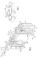
- FIG 2 is a perspective drawing of the data acquisition device shown in Figure 1.
- Figure 3 is a top plan view of a transducer holder which may be mounted on the data acquisition device shown in Figure 2.
- Figure 4 is a perspective view of an alternative holder which may be used to couple multiple transducers to a data acquisition device such as that shown in Figure 1.
- Figure 5 is a rear perspective view of the holder shown in Figure 4.
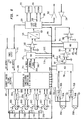
- Figure 6 is a functional block diagram, partly in schematic diagram form of the data acquisition device shown in Figure 2.
- Figure 7 is a block diagram, partly in schematic diagram form of a differential to single ended converter suitable for use in the data acquisition device shown in Figure 6.
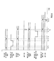
- Figure 8 is a timing diagram which is useful for describing the operation of the data acquisition device shown in Figures 2 and 6.
- Figure 1 shows a system which includes an exemplary data acquisition device 30 in accordance with the invention.
- Device 30 is configured to receive data representing blood pressure or both blood pressure and temperature.
- the device may be placed on a bed or a bedside table. Alternatively it may be attached to the bed, an intravenous pole or a dedicated stand.
- the data acquisition device is selectively and detachably coupled, by a single coupling line 34, to a display 20, which may be a portable display.
- Line 34 plugs into a port 35 of device 30. If for any reason, it is desirable to replace display 20 with a further selected display (not shown), this may be accomplished by detaching coupling line 34 from the display 20, and attaching the line 34 to the new display.
- Another data acquisition device 10 is also shown.
- Device 30 may be used alone or in combination with another device such as device 10, for monitoring multiple parameters in a data acquisition system.
- Device 10 may include a plurality of terminals 14 which are coupled, for example, to EKG electrodes.
- the device 10 may also include a plurality of terminals 12 which are coupled to resistance sensors such as temperature, nasal respiration or cardiac output thermodilution sensor leads by a plurality of receiving lines 16.
- Device 30 may be positioned independently of device 10, and of display 20. Device 30 is small enough in size to be conveniently located close to the patient.
- Data acquisition device 30 includes a housing 48 and means for detachably mounting the housing 48 to an external structure, such as an intravenous (IV) pole, a bed rail, a post, or a dedicated stand.
- the mounting means may be in the form of a clamp 46, a hook, a velcro fastener, or other known fastener.
- the clamp 46 allows rapid adjustment of the height of data acquisition device 30 when the patient's position is changed.
- the clamp 46 also allows the user to rapidly detach data acquisition device 30 when the patient is transported.
- FIG 2 is an enlarged view of device 30.
- the sensors, or pressure transducers are collocated with the data acquisition electronics, contained in a housing, and are mounted on the housing, proximate to the electronics. Only two transducers 302a and 302c are shown in Figure 2. The other two transducers (not shown) may be identical and are mounted in a the same manner. In the exemplary embodiment, the transducers are mounted on the front surface of housing 48. Each pressure transducer is inserted into one of four channels 38a-38d on the front surface of housing 48. Channels 38a-38d provide a means for detachably mounting the transducers to housing 48. Each pressure transducer includes a short cable 54 which is inserted into a connector 50a-50d.
- Connectors 50a-50d receive electrical signals representing pressure from the transducers. Each of the cables 54 transmits these signals from a respective transducer 302a-302d to the data acquisition electronics inside device 30. Connectors 50a-50d are collocated with respective mounting channels 38a-38d, to minimize the length of the cable 54 used to electrically couple the pressure transducers with the connectors 50a-50d.
- the transducers may be mounted in a detachable transducer holder 404, a portion of which is shown in Figure 3.
- Holder 404 is separate from data acquisition device 30.
- Holder 404 may have up to four members 406 adapted to fit into mounting channels 38a-38d of housing 48.
- Holder 404 includes three additional transducer channels (not shown) identical to channel 406 to receive three additional transducers (not shown), which may be identical to transducer 402.
- adapter 404 is configured to receive a transducer 402 which is smaller than channel 38a. It is understood by one skilled in the art that adapter 404 may be constructed to receive transducers of any size, and may have a transducer channel 406 which is larger or smaller than the mounting channel 38a.
- transducer holder 404 may be advantageous in a hospital where transducers of different sizes are procured from multiple sources. A single data acquisition device 30 may then be used in conjunction with any of these transducers. The hospital need only procure an additional holder having a transducer channel of the appropriate size for any new transducer 402.
- each channel 38a-38d includes electrodes 40a and 40b for contacting electrodes on the surface of the transducers. Electrical and mechanical couplings are simultaneously established by inserting the transducers into their respective channels. There is no need to connect separate cables to connectors 50a-50d.
- FIG. 4 shows the front plate 500 of an alternative embodiment of the device housing.
- Plate 500 has five raised members 560, 562, 564, 566 and 568 which form four variable width channels 502a-502d.
- Each channel 502a-502d includes three distinct sections (e.g., sections 504, 506, and 508 of channel 502a). Each section is sized to receive a pressure transducer 530 having mounting plates 532 and 534 of a predetermined width.
- Each channel 502a-502d includes a feed-through connector 510 (shown as a female connector) for mating with a connector 536 (as shown in Figure 5) on pressure transducer 530.
- Plate 500 may be molded of a suitable plastic material and may be molded without any holes for receiving connector 510. A rectangular hole may be subsequently stamped in at one of the three sections 514, 516 or 518 of channels 502a-502d. With this single hole, plate 500 is then dedicated for use with a transducer, having a size to fit in the channel section 514, 516, or 518 adjacent the hole, as shown in Figures 4 and 5. Alternatively, plate 500 may have three holes (not shown), each hole adjacent a respective section 514, 516 and 518 of channel 502a-502d.
- FIG. 5 a rear view of a plate 501 is shown.
- Plate 501 is similar to plate 500, except that the hole which receives connector 510 is located adjacent channel section 516 instead of section 518 as shown in Figure 4.
- the connector 536 on transducer 530 includes pins 538 for mating with connector 510 on plate 501.
- the transducer 530 has the male connector and plate 501 has the female connector. This configuration is preferred, because the pins 538 of the male connector are more prone to damage than the female connector.
- Transducer 530 is disposable, so it is cost effective to locate the pins on disposable transducer 530; although it is understood that transducer 530 could have a female connector and connector 510 could be male.
- device 30 includes 2 input ports 24a and 24b for receiving temperature data from invasive temperature sensors.
- data acquisition device 30 is a preconfigured, standalone (self contained) unit.
- device 30 includes all of the electronics required to receive the analog electrical signals, representing pressure measurements, from the pressure transducers, filter and clamp the signals, combine them into a single analog signal and convert the single analog signal into a digital output signal.
- This digital output signal may be transferred directly to display device 20 by wire 34 or by a wireless (e.g., infrared) link (not shown).
- device 30 is neither inserted into a bulky box or rack, nor into the display device itself, to form an electrical path to the display device.
- device 30 may be formed in a small enough package to be conveniently placed in a variety of locations in close proximity to the patient.
- Reducing the size of device 30 so that it is selectably positionable near the patient is advantageous because it reduces the length of the hose 56 which connects the catheter in the patient to the transducer.
- the shorter the hose the less likely it is to become twisted, bent or kinked, which could cause incorrect measurements.
- a shorter hose is also less likely to be accidentally jostled, struck or pulled, enhancing safety for the hose, the transducer, device 30 and most importantly, the patient.
- Data acquisition device 30 also has two control switches conveniently located on housing 48: a pressure zero switch 42 and a wedge start switch 44.
- a pressure zero switch 42 During a calibration operation, the fluid inlets to the respective transducers are opened up to atmospheric pressure (by disconnecting the hose), pressure zero switch 42 is then actuated by the operator. This causes device 30 to send a signal to display device 20. This pressure zero signal causes display device 20 to zero the pressure waveform on the display. Once the reference voltage is reset, the hose 56 which is connected to the patient is reconnected to the pressure transducer.
- the pulmonary artery wedge pressure measurement operation is simplified.
- the operator performs the catheter insertion and balloon inflation near the patient. Then the operator actuates switch 44 to start the wedge pressure measurement.
- Actuating switch 44 causes device 30 to transmit a wedge start signal to display device 20.
- the wedge start signal causes the display device to initiate a wedge pressure measurement, i.e., to display the data signals it receives using coefficients and processing parameters appropriate for wedge pressure measurement. Again, the operator does not need to walk over to the monitor, or walk around any hoses or wires to start the measurement.
- Another advantage of having the transducers close to the electronics (mounted on the housing 48) is that the electrical paths between the transducers and the electronics are short, so as to reduce radio frequency (RF) interference.
- RF radio frequency
- the noise added to each signal prior to amplification is reduced by shortening the electrical path over which the signal travels before amplification. Noise and signal transport artifacts are avoided, which would otherwise occur if the amplification were performed further from the patient and, even in the absence of external noise sources, if the impedances of the couplings to the patient were imbalanced.
- the signals are converted to digital form in an A/D converter (not shown) in the pod electronics before being transmitted across the comparatively long coupling line 34 between the data acquisition device 30 and the display device 20.
- the detachable coupling between the data acquisition device 30 and display device 20 is intended to include any manner of communicating the acquired data signals to display device 5 20, such as a wireless communication link (not shown), which may be an infrared link.
- FIG 6 is a block diagram of the pressure/temperature data acquisition device 30 shown in Figure 2.
- the device 30 receives data from up to four 5 pressure transducers 302a-302d and two temperature transducers 350a and 350b. Power is provided by a single step-down power supply 310.
- the output signals from the transducers 302a-302d are provided to respective clamping and filtering networks 304a-304d, to limit the dynamic range of the signals and remove noise.
- the output signals 303a, 303b from each of the networks 304a-304d are provided to a 5 differential-to-single-ended converter and 4-to-1 multiplexer 308.
- the differential-to-single-ended converter 308 generates a single signal 314 representative of pressure difference from each pair'of signals 303a and 303b.
- An advantageous aspect of this configuration is that power is conserved, relative to a system in which the excitation voltage is applied to all four transducers simultaneously.
- four transducers are used, consuming no more power than is required to operate one transducer continuously. It is particularly valuable to reduce power consumption if the data acquisition device is intended for use in conjunction with a portable display such as display device 20, with limited battery capacity. This feature allows operational transducers to continue to operate even when one transducer fails with an electrical short.
- the output signals from networks 304b-304d are converted to pressure difference signals.
- the converter 308 is controlled by signals 309a-309f sent over a timing bus 368.
- the timing bus 368 also controls the transducers, so that converter 308 acts as a time division multiplexer, transmitting signals representing the output signals of the respective transducers in round robin fashion.
- the output signal 314 is multiplexed together with reference pressure signals 316a, 316b in multiplexer 312.
- Multiplexer 312 is controlled by signals 313a-313c which are received from the timing bus 368.
- the signal 317 is boosted by amplifier 318 so that it occupies a range of values coextensive with the input range of the A/D converter 320, which converts it to digital form.
- the digital output data signal 322 is Manchester encoded in a logic gate array 324 and is sent out to the display device 20 by data transmitter 332.
- Logic 324 controls the timing for activating transducers 302a-302d by closing respective switches 370a-370d, for converting differential voltage to single-ended voltage in converter 308, and for multiplexing the output signals from converter 308.
- logic 324 Another function of logic 324 is to respond to actuation of either one of pressure zero switch 42 and wedge pressure switch 44. When one of the switches 42 and 44 is actuated, logic 324 causes device 30 to transmit a respective pressure zero signal or a wedge start signal to display device 20.
- Logic 324 may be implemented in application specific integrated circuits (ASIC), or using programmable array logic (PAL).
- a memory device which may be a conventional electrically erasable programmable read only memory (EEPROM) 326 is provided for local storage of calibration coefficients and/or alarm limits which may be used by gate array 324.
- a data receiver 334 receives commands from the display device 20.
- a second memory device which may also be an EEPROM 372 stores permanent data, such as the serial number or revision level of a printed circuit board. It is understood by those skilled in the art that this memory may be located outside of housing 48 (as shown by memory 434 in Figure 2) of blood pressure pod 30, and may be connected to pod 30. Memory 434 may be selectively detachable from pod 30.
- a single memory 434 is shown coupled to transducer 302c. Similar memories may be coupled to each transducer.
- each transducer has a respective memory, it is convenient to allow the memories to accompany the transducers when the patient moves.
- memory 434 may be detached from pod 30 and may be connected to another, equivalent pod for transportation to a different part of the hospital. This provides an additional element of flexibility in selectively coupling devices 30 to display device 20.
- Pod 30 may be disconnected from display device 20 and reconnected to another display without the need for time consuming data downloads from display device 20 to the other display.
- the output signals 351a and 351b from respective temperature transducers, 350a and 350b, are filtered and clamped by circuits 352a and 352b, to remove noise and to limit the signal range.
- the filtered signals are provided to multiplexer 356, which produces a single TDM signal 357.
- An offset signal 360 is added to the TDM signal 357 in adder 358, and the resulting signal is boosted in amplitude by amplifier 362.
- the amplified signal 363 is multiplexed together with plus and minus five volt monitor signals provided by the step down power supply 310 in multiplexer 364.
- the power supply monitor signals are provided to allow deviations from the nominal five volt operational power signal provided by power supply 310 to be detected.
- the multiplexer output signal is then boosted by amplifier 366 and the resulting signal is provided to A/D converter 320.
- the temperature data is provided to the logic gate array 324 where it is Manchester encoded and transmitted to the display.
- the capacitor 378 is accessed by differential multiplexer 308.
- the input signal to multiplexer 308 is differential.
- the output signal 314 of multiplexer 308 is differential, except that one of the differential output lines of multiplexer 308 is coupled to ground.
- One electrode of the capacitor is coupled to ground through multiplexer 308.
- the capacitor output signal changes from a differential voltage to a single ended voltage.
- the output signal 314 is thus a single ended voltage referenced to ground. This signal may be sensed by a single ended amplifier such as amplifier 318.
- Figure 7 shows in greater detail a portion of the circuitry shown in Figure 6. In particular, details of the differential to single-ended converter 308 are shown. Figure 7 only shows a single pressure transducer 302a, and its associated circuitry including: clamp and filter network 304a, switch 370a, and electrical paths 303a and 303b, 380a and 380b, and 390a. It is understood by one skilled in the art that these elements and electrical paths are replicated for each of the four transducer data acquisition circuits shown in Figure 6.
- switches 374 and 376 For converting the voltage signal provided by transducer 302a from a differential signal to a single-ended signal, two switches 374 and 376 control the flow of current from the transducer 302a. Switches 374 and 376 receive power from lines 386a, 386b, 388a and 388b. One terminal of transducer 302a is coupled to switch 374 and the other to switch 376. The differential output voltages 392 and 394 from respective switches 374 and 376 are applied across capacitor 378. Switches 374 and 376 receive control signals S1 and S2 from logic circuit 324 (shown in Figure 6). When signals S1 and S2 are set to their low voltage values, respective switches 374 and 376 are closed, applying the differential voltage signal across capacitor 378. When signals S1 and S2 are set to their high values, the switches are opened and capacitor 378 retains the differential voltage.
- FIG 8 is a timing diagram which shows the sampling of pressure data from two of the pressure transducers 302a and 302b. It is understood that the data shown represent only one half of a complete cycle for multiplexer 312. That is, the time between T0 and T8 is 3 milliseconds, or three 1-millisecond time slots. An additional 2 milliseconds pass before the output signal of the fourth transducer 302d is sampled by A/D converter 320 (shown in Figure 6).
- the temporal relationships between the activation of the second and third transducers 302b and 302c are the same as the temporal relationships between activation of the first and second pressure transducers 302a and 302b .
- switch 370a is closed, thereby applying excitation voltage PVREF to transducer 302a.
- Switch 370a remains closed for 1 millisecond, until T3.
- switches 374 and 376 are both closed, coupling capacitor 378 to the differential voltage across the output of transducer 302a, (between lines 392 and 394).
- Capacitor 378 charges up to the transducer output voltage through the equivalent series output impedance of transducer 302a.
- Capacitor 378 and the output impedance of transducer 302a form a resistance-capacitance (RC) network which filters noise during the period between T1 and T2, when capacitor 378 is charging.
- RC resistance-capacitance
- T2 occurs 15 microseconds before the end of the first time slot.
- switches 376 and 378 are opened, decoupling capacitor 378 and transducer 302a.
- differential multiplexer 312 couples capacitor 378 to the input of amplifier 318 (shown in Figure 6) via a single ended ground referenced output line 317.
- the differential voltage on capacitor 378 is thus transformed into a single-ended voltage.
- common mode noise voltage is removed.
- Multiplexer 312 samples the voltage across capacitor 378 until T7, which is 1 millisecond after T3.
- the output signal on line 317 is amplified by amplifier 318 (shown in Figure 6) and is transmitted to A/D converter 320 (shown in Figure 6).
- A/D converter 320 does not begin sampling immediately at T3. Instead, there is a suitable settling time between T3 and T6 before A/D converter 320 samples the output signal 319 of amplifier 318.
- each transducer 302a-302d charges a capacitor in converter 308, the voltage from the last previously charged capacitor is amplified and sampled.
- switch 370b is closed, activating transducer 302b.
- a further pair of switches are closed to apply a voltage representing the voltage across transducer 302b, to a further capacitor (not shown).
- the further pair of switches are opened.
- the voltage across the further capacitor is sampled by multiplexer 312 between T7 and T9, and digitized by A/D converter 320 between T8 and T9.
- an excitation voltage is applied to the third transducer 302c during the third time slot and its output signal is digitized during the fourth time slot.
- the excitation voltage is applied to the fourth transducer 302d during the fourth time slot and its output signal is digitized during the fifth time slot.
- the excitation voltage is applied to the first transducer 302a again during the fifth time slot and its output signal is digitized during the sixth time slot.
- the circuit topology described above has several advantageous aspects. Power consumption is low, because the reference voltage is only applied to one transducer at a time. A single current limited voltage reference is shared by the four transducers 302a-302d, which may reduce costs.
- the circuit described above has low susceptibility to noise that is common mode in nature. This is particularly important in a hospital setting, where electro-surgery units (ESU) often produce a high frequency common mode noise signal.
- ESU electro-surgery units
- the circuitry shown in Figures 6 and 7 has a high common mode rejection ratio that is essentially independent of frequency.
- the differential instrumentation amplifiers used in these prior art cartridges typically have lower common mode rejection for high frequency noise signals (such as those produced by ESUs) than for low frequency noise signals.
- the current limited voltage reference 306 provides a reference voltage to one of the transducers 302a-302d at a time, during its respective time slot.
- Voltage reference 306 includes means to sense when one of the transducers 302a-302d has developed a short circuit. Voltage reference 306 will not deliver current in excess of a predetermined limit, to protect the patient and the equipment from further damage. In such a condition, the voltage reference signal 390a-390d for the failed transducer 302a-302d is held to the predetermined current limit each time device 30 attempts to apply an excitation voltage to the failed transducer.
- Voltage reference 306 is able to stabilize at the predetermined current limit during the 15 microsecond period between closing switch 370a-370d and closing switches 374 and 376 to apply voltage to capacitor 378. Voltage reference 306 is also able to return to the desired reference voltage during the same 15 microsecond period before the switches are closed to apply the differential voltage from the next transducer.
- circuitry for receiving and processing signals representing temperature from temperature sensors 350a and 350b The temperatures signals are conditioned by filters 352a and 352b. The filtered signals are multiplexed together in a multiplexer 356. A multiplexed signal is provided to A/D converter 320 to provide a single digital temperature signal 322.
- the exemplary embodiments include data acquisition devices 30 adapted to receive up to four transducers, it is understood that devices in accordance with the invention may be constructed for use with a different number of transducers.
Landscapes
- Health & Medical Sciences (AREA)
- Engineering & Computer Science (AREA)
- Life Sciences & Earth Sciences (AREA)
- Public Health (AREA)
- General Health & Medical Sciences (AREA)
- Medical Informatics (AREA)
- Biomedical Technology (AREA)
- Cardiology (AREA)
- Molecular Biology (AREA)
- Veterinary Medicine (AREA)
- Heart & Thoracic Surgery (AREA)
- Biophysics (AREA)
- Physics & Mathematics (AREA)
- Surgery (AREA)
- Animal Behavior & Ethology (AREA)
- Primary Health Care (AREA)
- Physiology (AREA)
- Pathology (AREA)
- Epidemiology (AREA)
- Pulmonology (AREA)
- Computer Networks & Wireless Communication (AREA)
- Business, Economics & Management (AREA)
- General Business, Economics & Management (AREA)
- Measuring And Recording Apparatus For Diagnosis (AREA)
- Measuring Pulse, Heart Rate, Blood Pressure Or Blood Flow (AREA)
Claims (15)
- Datenerfassungsvorrichtung (30) zum Gebrauch mit einem Patientenüberwachungssystem, wobei das Patientenüberwachungssystem eine Signalverarbeitungs- und Anzeigevorrichtung (20) enthält und mehrere mit einem Patienten verbundene Druckmesswandler (302), und die Messwandler mehrere Blutdrucksignale des Patienten erzeugen, und die Datenerfassungsvorrichtung umfasst:ein erstes Gehäuse, das von einem zweiten Gehäuse, das die Signalverarbeitungs- und Anzeigevorrichtung (20) enthält, entfernt und unabhängig plaziert werden kann, wobei das erste Gehäuse eine Montageeinrichtung (38) aufweist, mit der man die Druckmesswandler (302) abnehmbar am ersten Gehäuse befestigen kann;eine Empfangsvorrichtung (50a .. 50d) im ersten Gehäuse, die Signale empfängt, die den Blutdruck der Druckmesswandler (302) darstellen;eine mit der Empfangsvorrichtung (50a .. 50d) verbundene Aufbereitungsvorrichtung, die in dem ersten Gehäuse untergebracht ist und auf Steuersignale aus der Signalverarbeitungs- und Anzeigevorrichtung (20) anspricht, damit sie kontrollierbar die empfangenen Signale aufbereitet, die den von der Signalverarbeitungs- und Anzeigevorrichtung übertragenen Blutdruck darstellen, wobei die Aufbereitungsvorrichtung, da sie im ersten Gehäuse untergebracht ist, unabhängig von der Signalverarbeitungs- und Anzeigevorrichtung (20) angeordnet werden kann, die sich im zweiten Gehäuse befindet;eine Vorrichtung (54), die die Druckmesswandler elektrisch mit der Aufbereitungsvorrichtung verbindet; undeine bidirektionale Kommunikationsvorrichtung (34), die die Aufbereitungsvorrichtung ausgewählt mit der Signalverarbeitungs- und Anzeigevorrichtung (20) verbindet, die sich im gleichen Patientenüberwachungsbereich befindet, damit die Steuersignale von der im zweiten Gehäuse untergebrachten Signalverarbeitungs- und Anzeigevorrichtung (20) an die im ersten Gehäuse untergebrachte Datenerfassungsvorrichtung übertragen werden, die Aufbereitungsvorrichtung gesteuert wird und die aufbereiteten Blutdrucksignale aus dem ersten Gehäuse an die Signalverarbeitungs- und Anzeigevorrichtung im zweiten Gehäuse übertragen werden.
- Datenerfassungsvorrichtung nach Anspruch 1, wobei die Empfangsvorrichtung einen Verbinder enthält, der gemeinsam mit der Montagevorrichtung angeordnet ist.
- Datenerfassungsvorrichtung nach Anspruch 1, wobei die Montagevorrichtung einen Kanal (38a .. 38d) im ersten Gehäuse enthält, und der Kanal so bemessen ist, dass er die Befestigungseinrichtung des Messwandlers aufnimmt.
- Datenerfassungsvorrichtung nach Anspruch 1, zudem umfassend einen Schalter (42), der am ersten Gehäuse untergebracht und mit der bidirektionalen Kommunikationsvorrichtung verbunden ist und ein Druck-Null-Signal an die Anzeige überträgt, um damit die Anzeigevorrichtung zu veranlassen, das von der Aufbereitungsvorrichtung empfangene aufbereitete Signal einem Kurvendarstellungswert von Null zuzuordnen.
- Vorrichtung nach Anspruch 3, wobei die Montagevorrichtung einen Messwandlerhalter umfasst, der einen weiteren Kanal zum Aufnehmen des Messwandlers aufweist, der für die Aufnahme des Messwandlers bemessen ist, und wobei der Kanal im ersten Gehäuse für die Aufnahme des Halters bemessen ist.
- Datenerfassungsvorrichtung nach irgendeinem der vorhergehenden Ansprüche, zudem umfassend einen auf dem ersten Gehäuse angeordneten Schalter (44), der ein Verschlussstartsignal an die Anzeige überträgt und die Anzeigevorrichtung damit veranlasst, einen Pulmonalarterienverschluss-Messvorgang zu beginnen.
- Datenerfassungsvorrichtung nach irgendeinem der vorhergehenden Ansprüche, zudem umfassend ein Hilfsmittel, mit dem man die Vorrichtung relativ zum Patienten unterschiedlich hoch anordnen kann.
- Datenerfassungsvorrichtung nach Anspruch 7, wobei das Anordnungshilfsmittel eine Vorrichtung (46) umfasst, mit der man das erste Gehäuse an einem Infusionsständer montieren kann.
- Datenerfassungsvorrichtung nach Anspruch 7, wobei das Anordnungshilfsmittel eine Vorrichtung (46) umfasst, mit der man das erste Gehäuse an einem Bett montieren kann.
- Datenerfassungsvorrichtung nach irgendeinem der vorhergehenden Ansprüche, wobei die Aufbereitungsvorrichtung eine Verknüpfungsvorrichtung umfasst, damit man die Signale, die den von allen Messwandlern empfangenen Blutdruck darstellen, über ein einziges Kabel übertragen kann.
- Datenerfassungsvorrichtung nach Anspruch 10, wobei die Verknüpfungsvorrichtung einen Zeitmultiplex enthält.
- Datenerfassungsvorrichtung nach irgendeinem der vorhergehenden Ansprüche, wobei die Aufbereitungsvorrichtung eine Schaltervorrichtung beinhaltet, die auf die Steuersignale anspricht und von allen Messwandlern ausgewählt zu einem Zeitpunkt nur einen für sich in Gang setzt.
- Datenerfassungsvorrichtung nach irgendeinem der vorhergehenden Ansprüche, wobei die den Blutdruck darstellenden Signale Spannungsdifferenzsignale sind, und die Aufbereitungsvorrichtung eine auf die Steuersignale ansprechende Einrichtung enthält, die die Spannungsdifferenzsignale in unsymmetrische Spannungssignale umsetzt.
- Datenerfassungsvorrichtung nach irgendeinem der vorhergehenden Ansprüche, zudem umfassend eine Einrichtung, die auf die Steuersignale anspricht und ein Bezugsspannungssignal mit einem vorbestimmten Spannungswert und einer vorbestimmten Stromstärke an den Messwandler anlegt und Einrichtungen einschließt, die die Stromstärke des Bezugsspannungssignals unter einer vorbestimmten Grenze halten.
- Datenerfassungsvorrichtung nach irgendeinem der vorhergehenden Ansprüche, zudem umfassend einen Speicher zum Speichern von Daten, die Kalibrierdaten für die Druckmesswandler und Alarmgrenzen enthalten.
Applications Claiming Priority (2)
| Application Number | Priority Date | Filing Date | Title |
|---|---|---|---|
| US989416 | 1992-12-11 | ||
| US07/989,416 US5566676A (en) | 1992-12-11 | 1992-12-11 | Pressure data acquisition device for a patient monitoring system |
Publications (3)
| Publication Number | Publication Date |
|---|---|
| EP0603666A2 EP0603666A2 (de) | 1994-06-29 |
| EP0603666A3 EP0603666A3 (de) | 1995-05-10 |
| EP0603666B1 true EP0603666B1 (de) | 2001-07-25 |
Family
ID=25535094
Family Applications (1)
| Application Number | Title | Priority Date | Filing Date |
|---|---|---|---|
| EP93119878A Expired - Lifetime EP0603666B1 (de) | 1992-12-11 | 1993-12-09 | Druck-Datenüberwachungsgerät für Patienten-Überwachungssystem |
Country Status (5)
| Country | Link |
|---|---|
| US (1) | US5566676A (de) |
| EP (1) | EP0603666B1 (de) |
| AT (1) | ATE203383T1 (de) |
| DE (1) | DE69330487T2 (de) |
| DK (1) | DK0603666T3 (de) |
Cited By (1)
| Publication number | Priority date | Publication date | Assignee | Title |
|---|---|---|---|---|
| US9247886B2 (en) | 2004-10-07 | 2016-02-02 | Tensys Medical, Inc. | Compact apparatus and methods for non-invasively measuring hemodynamic parameters |
Families Citing this family (79)
| Publication number | Priority date | Publication date | Assignee | Title |
|---|---|---|---|---|
| GB2288922B (en) | 1994-04-25 | 1998-04-01 | John Edward Mcgrath | Patient monitoring apparatus |
| US5937950A (en) * | 1996-12-02 | 1999-08-17 | Medex, Inc. | Cable system for medical equipment |
| DE19703045A1 (de) * | 1997-01-28 | 1998-07-30 | Mueller & Sebastiani Elek Gmbh | Medizinisches Diagnosegerät |
| EP0897690B1 (de) * | 1997-08-15 | 2013-04-24 | Academisch Ziekenhuis Leiden h.o.d.n. LUMC | Druckfühler für den Gebrauch in einem Aneurysma |
| US6099476A (en) * | 1997-10-15 | 2000-08-08 | W. A. Baum Co., Inc. | Blood pressure measurement system |
| US7558616B2 (en) * | 1999-03-11 | 2009-07-07 | Biosense, Inc. | Guidance of invasive medical procedures using implantable tags |
| US7174201B2 (en) | 1999-03-11 | 2007-02-06 | Biosense, Inc. | Position sensing system with integral location pad and position display |
| US7575550B1 (en) | 1999-03-11 | 2009-08-18 | Biosense, Inc. | Position sensing based on ultrasound emission |
| US7549960B2 (en) * | 1999-03-11 | 2009-06-23 | Biosense, Inc. | Implantable and insertable passive tags |
| US7590441B2 (en) * | 1999-03-11 | 2009-09-15 | Biosense, Inc. | Invasive medical device with position sensing and display |
| US6241679B1 (en) * | 1999-05-24 | 2001-06-05 | Medwave, Inc. | Non-invasive blood pressure sensing device and method using transducer with associate memory |
| US6471655B1 (en) | 1999-06-29 | 2002-10-29 | Vitalwave Corporation | Method and apparatus for the noninvasive determination of arterial blood pressure |
| EP1211975A2 (de) * | 1999-09-03 | 2002-06-12 | Tensys Medical, Inc. | Intelligenter bioparametersensor und verfahren |
| US6407335B1 (en) * | 1999-11-19 | 2002-06-18 | Alaris Medical Systems, Inc. | Medical device interface system |
| US6554774B1 (en) | 2000-03-23 | 2003-04-29 | Tensys Medical, Inc. | Method and apparatus for assessing hemodynamic properties within the circulatory system of a living subject |
| EP1156336A1 (de) * | 2000-05-16 | 2001-11-21 | AVL Medical Instruments AG | Analysensystem zur Analyse medizinischer Proben |
| US6506162B1 (en) * | 2000-06-09 | 2003-01-14 | K-Jump Health Co., Ltd. | Electronic blood pressure gauge equipped with dismountable external memory device |
| US6705990B1 (en) | 2000-07-25 | 2004-03-16 | Tensys Medical, Inc. | Method and apparatus for monitoring physiologic parameters of a living subject |
| US6558335B1 (en) | 2000-11-22 | 2003-05-06 | Medwave, Inc | Wrist-mounted blood pressure measurement device |
| US6636769B2 (en) | 2000-12-18 | 2003-10-21 | Biosense, Inc. | Telemetric medical system and method |
| US6658300B2 (en) | 2000-12-18 | 2003-12-02 | Biosense, Inc. | Telemetric reader/charger device for medical sensor |
| US6638231B2 (en) | 2000-12-18 | 2003-10-28 | Biosense, Inc. | Implantable telemetric medical sensor and method |
| US6652464B2 (en) | 2000-12-18 | 2003-11-25 | Biosense, Inc. | Intracardiac pressure monitoring method |
| US6783499B2 (en) | 2000-12-18 | 2004-08-31 | Biosense, Inc. | Anchoring mechanism for implantable telemetric medical sensor |
| US6746404B2 (en) * | 2000-12-18 | 2004-06-08 | Biosense, Inc. | Method for anchoring a medical device between tissue |
| US6635020B2 (en) * | 2001-06-26 | 2003-10-21 | Thermometrics | Reusable fluid pressure transducer monitoring apparatus |
| US6855115B2 (en) * | 2002-01-22 | 2005-02-15 | Cardiomems, Inc. | Implantable wireless sensor for pressure measurement within the heart |
| US7699059B2 (en) * | 2002-01-22 | 2010-04-20 | Cardiomems, Inc. | Implantable wireless sensor |
| US7317409B2 (en) | 2002-01-30 | 2008-01-08 | Tensys Medical, Inc. | Apparatus and method for interfacing time-variant signals |
| US6730038B2 (en) | 2002-02-05 | 2004-05-04 | Tensys Medical, Inc. | Method and apparatus for non-invasively measuring hemodynamic parameters using parametrics |
| US8079559B1 (en) | 2002-02-28 | 2011-12-20 | Sscor, Inc. | Aspirator bracket |
| US6850788B2 (en) | 2002-03-25 | 2005-02-01 | Masimo Corporation | Physiological measurement communications adapter |
| US7060075B2 (en) * | 2002-07-18 | 2006-06-13 | Biosense, Inc. | Distal targeting of locking screws in intramedullary nails |
| JP3697230B2 (ja) * | 2002-07-26 | 2005-09-21 | コーリンメディカルテクノロジー株式会社 | 血圧監視装置 |
| US7147604B1 (en) | 2002-08-07 | 2006-12-12 | Cardiomems, Inc. | High Q factor sensor |
| US7245117B1 (en) | 2004-11-01 | 2007-07-17 | Cardiomems, Inc. | Communicating with implanted wireless sensor |
| CA2539261C (en) | 2003-09-16 | 2011-05-17 | Cardiomems, Inc. | Implantable wireless sensor |
| US8026729B2 (en) | 2003-09-16 | 2011-09-27 | Cardiomems, Inc. | System and apparatus for in-vivo assessment of relative position of an implant |
| US20060094935A1 (en) * | 2004-10-20 | 2006-05-04 | Coulbourn Instruments, L.L.C. | Portable psychophysiology system and method of use |
| JP2008526443A (ja) | 2005-01-13 | 2008-07-24 | ウェルチ・アリン・インコーポレーテッド | 生命兆候モニタ |
| US7647836B2 (en) | 2005-02-10 | 2010-01-19 | Cardiomems, Inc. | Hermetic chamber with electrical feedthroughs |
| US7662653B2 (en) | 2005-02-10 | 2010-02-16 | Cardiomems, Inc. | Method of manufacturing a hermetic chamber with electrical feedthroughs |
| US8118749B2 (en) * | 2005-03-03 | 2012-02-21 | Cardiomems, Inc. | Apparatus and method for sensor deployment and fixation |
| US8021307B2 (en) | 2005-03-03 | 2011-09-20 | Cardiomems, Inc. | Apparatus and method for sensor deployment and fixation |
| US7621036B2 (en) | 2005-06-21 | 2009-11-24 | Cardiomems, Inc. | Method of manufacturing implantable wireless sensor for in vivo pressure measurement |
| AU2006262287A1 (en) | 2005-06-21 | 2007-01-04 | Cardiomems, Inc. | Method of manufacturing implantable wireless sensor for in vivo pressure measurement |
| US7595723B2 (en) | 2005-11-14 | 2009-09-29 | Edwards Lifesciences Corporation | Wireless communication protocol for a medical sensor system |
| CA2645770C (en) | 2006-03-14 | 2016-01-26 | Cardiomems, Inc. | Communicating with an implanted wireless sensor |
| US8506497B2 (en) | 2006-05-13 | 2013-08-13 | Tensys Medical, Inc. | Continuous positioning apparatus and methods |
| US7704212B2 (en) * | 2006-06-14 | 2010-04-27 | Spacelabs Healthcare | Reusable invasive fluid pressure monitoring apparatus and method |
| ES2426483T3 (es) * | 2006-07-05 | 2013-10-23 | Elcam Medical Agricultural Cooperative Association Ltd. | Sistema de monitorización médica inalámbrico |
| US8840549B2 (en) | 2006-09-22 | 2014-09-23 | Masimo Corporation | Modular patient monitor |
| US9161696B2 (en) | 2006-09-22 | 2015-10-20 | Masimo Corporation | Modular patient monitor |
| US20080234555A1 (en) * | 2007-03-23 | 2008-09-25 | Stryker Corporation | Patient care system |
| CA2705352A1 (en) | 2007-10-12 | 2009-04-16 | Tensys Medical, Inc. | Apparatus and methods for non-invasively measuring a patient's arterial blood pressure |
| DE102008058101A1 (de) * | 2008-11-18 | 2010-05-20 | Bernd Beck | Verfahren zur Durchführung eines Nullpunktabgleichs eines Patientenüberwachungssystems und dazugehöriges Patientenüberwachungssystem |
| US20110208015A1 (en) | 2009-07-20 | 2011-08-25 | Masimo Corporation | Wireless patient monitoring system |
| DE102009039953A1 (de) | 2009-08-28 | 2011-03-03 | Bernd Beck | Messdatenumsetzer für ein Patientenüberwachungssystem |
| US9153112B1 (en) | 2009-12-21 | 2015-10-06 | Masimo Corporation | Modular patient monitor |
| EP2766834B1 (de) | 2011-10-13 | 2022-04-20 | Masimo Corporation | Medizinischer überwachungshub |
| US9943269B2 (en) | 2011-10-13 | 2018-04-17 | Masimo Corporation | System for displaying medical monitoring data |
| US10307111B2 (en) | 2012-02-09 | 2019-06-04 | Masimo Corporation | Patient position detection system |
| US10149616B2 (en) | 2012-02-09 | 2018-12-11 | Masimo Corporation | Wireless patient monitoring device |
| US9749232B2 (en) | 2012-09-20 | 2017-08-29 | Masimo Corporation | Intelligent medical network edge router |
| US10832818B2 (en) | 2013-10-11 | 2020-11-10 | Masimo Corporation | Alarm notification system |
| US20160100809A1 (en) * | 2014-10-10 | 2016-04-14 | Xhale, Inc. | Parameter modules including detachable processing devices and methods of using the same |
| CN113367671A (zh) | 2015-08-31 | 2021-09-10 | 梅西莫股份有限公司 | 无线式病人监护系统和方法 |
| EP3376940A4 (de) * | 2015-11-18 | 2018-12-05 | Edwards Lifesciences Corporation | Kabelhubvorrichtung |
| US10582981B2 (en) | 2016-02-02 | 2020-03-10 | Stryker Corporation | Accessory support and coupling systems for an accessory support |
| US10617302B2 (en) | 2016-07-07 | 2020-04-14 | Masimo Corporation | Wearable pulse oximeter and respiration monitor |
| US11076777B2 (en) | 2016-10-13 | 2021-08-03 | Masimo Corporation | Systems and methods for monitoring orientation to reduce pressure ulcer formation |
| USD807514S1 (en) * | 2016-12-27 | 2018-01-09 | Draeger Medical Systems, Inc. | Electronic visual display system |
| USD807513S1 (en) * | 2016-12-27 | 2018-01-09 | Draeger Medical Systems, Inc. | Electronic visual display system |
| WO2019204368A1 (en) | 2018-04-19 | 2019-10-24 | Masimo Corporation | Mobile patient alarm display |
| US11204622B2 (en) * | 2019-05-24 | 2021-12-21 | Drägerwerk AG & Co. KGaA | Systems, monitor mounts, monitors, racks, modules, and cable holders |
| JP2023518303A (ja) | 2020-03-20 | 2023-04-28 | マシモ・コーポレイション | 非侵襲的な体温測定のためのウェアラブルデバイス |
| USD974193S1 (en) | 2020-07-27 | 2023-01-03 | Masimo Corporation | Wearable temperature measurement device |
| USD980091S1 (en) | 2020-07-27 | 2023-03-07 | Masimo Corporation | Wearable temperature measurement device |
| USD1000975S1 (en) | 2021-09-22 | 2023-10-10 | Masimo Corporation | Wearable temperature measurement device |
Family Cites Families (35)
| Publication number | Priority date | Publication date | Assignee | Title |
|---|---|---|---|---|
| DE6948919U (de) * | 1969-12-16 | 1970-03-19 | Bbc Brown Boveri & Cie | Wandmonitor zur patientenueberwachung |
| US3848582A (en) * | 1972-07-10 | 1974-11-19 | Medical Res Labor Inc | Portable electrocardiographic signal apparatus |
| US3858576A (en) * | 1973-05-23 | 1975-01-07 | Sachs Elektronik Kg Hugo | Portable electrocardioscope |
| US3868679A (en) * | 1973-10-09 | 1975-02-25 | Gen Electric | Blood pressure amplifier with zero balancing means |
| DE2813764C3 (de) * | 1978-03-30 | 1981-09-03 | Siemens AG, 1000 Berlin und 8000 München | Elektromedizinisches Gerät zur Abnahme und Verarbeitung von elektrischen physiologischen Signalen |
| JPS5558154A (en) * | 1978-10-24 | 1980-04-30 | Toshimitsu Mushiya | Electronic diagnosis device |
| US4356486A (en) * | 1978-11-01 | 1982-10-26 | Medimetric Company | Telemetering system for operating room and the like |
| WO1981002832A1 (en) * | 1980-03-31 | 1981-10-15 | Datamedix Inc | Medical monitor |
| US4356475A (en) * | 1980-09-12 | 1982-10-26 | Siemens Aktiengesellschaft | System containing a predetermined number of monitoring devices and at least one central station |
| US4325385A (en) * | 1980-09-19 | 1982-04-20 | Simonsen & Weel's Eftf. A/S | Patient monitoring equipment |
| US4378021A (en) * | 1981-02-18 | 1983-03-29 | Strand Eric J | Electronic EKG measurement mode selection system |
| NL193256C (nl) * | 1981-11-10 | 1999-04-02 | Cordis Europ | Sensorsysteem. |
| FR2535964A1 (fr) * | 1982-11-17 | 1984-05-18 | Mesnard Guy | Appareillage de mesure, de traitement, de stockage et d'affichage de signaux biomedicaux |
| FR2557318A1 (fr) * | 1983-12-26 | 1985-06-28 | A2F | Dispositif electronique assurant une interface universelle entre des capteurs et un appareil de saisie et de traitement des signaux en provenance de ces capteurs |
| US4576181A (en) * | 1984-05-09 | 1986-03-18 | Utah Medical Products | Disposable pressure transducer apparatus for medical use |
| US4873654A (en) * | 1984-06-11 | 1989-10-10 | Safe-Test, Inc. | Testing device and method for inflatable objects |
| JPS618002U (ja) * | 1984-06-18 | 1986-01-18 | 日本光電工業株式会社 | 有線式患者監視装置用入力装置 |
| US4606352A (en) * | 1984-07-13 | 1986-08-19 | Purdue Research Foundation | Personal electrocardiogram monitor |
| JPS6125525A (ja) * | 1984-07-13 | 1986-02-04 | 住友電気工業株式会社 | 患者監視装置 |
| US4577639A (en) * | 1984-11-08 | 1986-03-25 | Spacelabs, Inc. | Apparatus and method for automatic lead selection in electrocardiography |
| US4608994A (en) * | 1984-12-20 | 1986-09-02 | Matsushita Electric Industrial Co., Ltd. | Physiological monitoring system |
| US4724844A (en) * | 1985-06-26 | 1988-02-16 | Stephen Rafelson | Vital sign modular unit |
| US5012411A (en) * | 1985-07-23 | 1991-04-30 | Charles J. Policastro | Apparatus for monitoring, storing and transmitting detected physiological information |
| US5029590A (en) * | 1985-08-09 | 1991-07-09 | Allain Joseph L | Portable, life detection monitor system |
| US4895161A (en) * | 1986-09-26 | 1990-01-23 | Marquette Electronics | Transportable data module and display unit for patient monitoring system |
| US4715385A (en) * | 1986-09-26 | 1987-12-29 | Marquette Electronics, Inc. | Patient monitoring system having transportable data module and display unit |
| US5006835A (en) * | 1987-08-07 | 1991-04-09 | Hewlett-Packard Company | Remote calibrating for pressure transducer |
| US4895385A (en) | 1987-09-18 | 1990-01-23 | Becoat Billie J | Kit for converting a bicycle to a dual wheel driven cycle |
| US4966154A (en) * | 1988-02-04 | 1990-10-30 | Jonni Cooper | Multiple parameter monitoring system for hospital patients |
| US4924871A (en) * | 1988-02-26 | 1990-05-15 | Colin Electronics Co., Ltd. | Motion artifact detection for continuous blood pressure monitor transducer |
| US4970900A (en) * | 1989-01-31 | 1990-11-20 | Baxter International, Inc. | Pole mount organizer with modular interconnection receptacles |
| US5025808A (en) * | 1990-01-31 | 1991-06-25 | Marquette Electronics, Inc. | Cardiac monitoring method and apparatus |
| NL9001571A (nl) * | 1990-07-10 | 1992-02-03 | Viggo Spectramed B V | Verbindingsinrichting. |
| US5036856A (en) * | 1990-07-19 | 1991-08-06 | Thornton William E | Cardiovascular monitoring system |
| DE69215204T2 (de) * | 1992-01-29 | 1997-03-13 | Hewlett Packard Gmbh | Verfahren und System zur Überwachung von Lebensfunktionen |
-
1992
- 1992-12-11 US US07/989,416 patent/US5566676A/en not_active Expired - Lifetime
-
1993
- 1993-12-09 DK DK93119878T patent/DK0603666T3/da active
- 1993-12-09 EP EP93119878A patent/EP0603666B1/de not_active Expired - Lifetime
- 1993-12-09 DE DE69330487T patent/DE69330487T2/de not_active Expired - Lifetime
- 1993-12-09 AT AT93119878T patent/ATE203383T1/de not_active IP Right Cessation
Cited By (1)
| Publication number | Priority date | Publication date | Assignee | Title |
|---|---|---|---|---|
| US9247886B2 (en) | 2004-10-07 | 2016-02-02 | Tensys Medical, Inc. | Compact apparatus and methods for non-invasively measuring hemodynamic parameters |
Also Published As
| Publication number | Publication date |
|---|---|
| DE69330487D1 (de) | 2001-08-30 |
| DK0603666T3 (da) | 2001-11-05 |
| ATE203383T1 (de) | 2001-08-15 |
| US5566676A (en) | 1996-10-22 |
| DE69330487T2 (de) | 2002-04-25 |
| EP0603666A2 (de) | 1994-06-29 |
| EP0603666A3 (de) | 1995-05-10 |
Similar Documents
| Publication | Publication Date | Title |
|---|---|---|
| EP0603666B1 (de) | Druck-Datenüberwachungsgerät für Patienten-Überwachungssystem | |
| US5375604A (en) | Transportable modular patient monitor | |
| US6221012B1 (en) | Transportable modular patient monitor with data acquisition modules | |
| US7197357B2 (en) | Wireless ECG system | |
| US8255041B2 (en) | Wireless ECG system | |
| US8897865B2 (en) | ECG lead system | |
| US5038800A (en) | System for monitoring patient by using LAN | |
| US20050165323A1 (en) | Physiological signal monitoring apparatus and method | |
| US20080081960A1 (en) | Floating physiological data acquisition system with expandable ECG and EEG | |
| EP1519677A2 (de) | Drahtlose ekg-vorrichtung | |
| JP3697628B2 (ja) | 生体信号検出装置およびホルタ心電計 | |
| WO2004002301A2 (en) | Wireless ecg system | |
| JP2006501873A (ja) | 無線ecgシステム | |
| WO1994013197A1 (en) | Data acquisition pod for a patient monitoring system | |
| US20080281163A1 (en) | Apparatus and method for acquiring medical data | |
| EP4062832A1 (de) | Physiologisches messsystem, biosignalverarbeitungseinheit und verfahren | |
| WO2000067636A1 (en) | Physiological signal acquisition cable | |
| CN210576937U (zh) | 心电导联线的转接器 | |
| CN109688169B (zh) | 将带传感器的医疗装置接入通信网络的方法及装置 | |
| CN109688170B (zh) | 将带传感器的医疗装置接入通信网络的方法及装置 | |
| JPH0553493B2 (de) |
Legal Events
| Date | Code | Title | Description |
|---|---|---|---|
| PUAI | Public reference made under article 153(3) epc to a published international application that has entered the european phase |
Free format text: ORIGINAL CODE: 0009012 |
|
| AK | Designated contracting states |
Kind code of ref document: A2 Designated state(s): AT DE DK FR GB IT NL SE |
|
| PUAL | Search report despatched |
Free format text: ORIGINAL CODE: 0009013 |
|
| AK | Designated contracting states |
Kind code of ref document: A3 Designated state(s): AT DE DK FR GB IT NL SE |
|
| 17P | Request for examination filed |
Effective date: 19950621 |
|
| 17Q | First examination report despatched |
Effective date: 19980821 |
|
| GRAG | Despatch of communication of intention to grant |
Free format text: ORIGINAL CODE: EPIDOS AGRA |
|
| GRAG | Despatch of communication of intention to grant |
Free format text: ORIGINAL CODE: EPIDOS AGRA |
|
| GRAH | Despatch of communication of intention to grant a patent |
Free format text: ORIGINAL CODE: EPIDOS IGRA |
|
| GRAH | Despatch of communication of intention to grant a patent |
Free format text: ORIGINAL CODE: EPIDOS IGRA |
|
| GRAA | (expected) grant |
Free format text: ORIGINAL CODE: 0009210 |
|
| AK | Designated contracting states |
Kind code of ref document: B1 Designated state(s): AT DE DK FR GB IT NL SE |
|
| REF | Corresponds to: |
Ref document number: 203383 Country of ref document: AT Date of ref document: 20010815 Kind code of ref document: T |
|
| RIC1 | Information provided on ipc code assigned before grant |
Free format text: 7A 61B 5/00 A, 7A 61B 5/0205 B, 7G 06F 19/00 B |
|
| REF | Corresponds to: |
Ref document number: 69330487 Country of ref document: DE Date of ref document: 20010830 |
|
| REG | Reference to a national code |
Ref country code: DK Ref legal event code: T3 |
|
| ET | Fr: translation filed | ||
| REG | Reference to a national code |
Ref country code: GB Ref legal event code: IF02 |
|
| PLBE | No opposition filed within time limit |
Free format text: ORIGINAL CODE: 0009261 |
|
| STAA | Information on the status of an ep patent application or granted ep patent |
Free format text: STATUS: NO OPPOSITION FILED WITHIN TIME LIMIT |
|
| 26N | No opposition filed | ||
| PGFP | Annual fee paid to national office [announced via postgrant information from national office to epo] |
Ref country code: AT Payment date: 20041122 Year of fee payment: 12 |
|
| REG | Reference to a national code |
Ref country code: GB Ref legal event code: 732E |
|
| REG | Reference to a national code |
Ref country code: FR Ref legal event code: TP Ref country code: FR Ref legal event code: CD |
|
| PGFP | Annual fee paid to national office [announced via postgrant information from national office to epo] |
Ref country code: NL Payment date: 20051116 Year of fee payment: 13 |
|
| PG25 | Lapsed in a contracting state [announced via postgrant information from national office to epo] |
Ref country code: AT Free format text: LAPSE BECAUSE OF NON-PAYMENT OF DUE FEES Effective date: 20051209 |
|
| PGFP | Annual fee paid to national office [announced via postgrant information from national office to epo] |
Ref country code: SE Payment date: 20051227 Year of fee payment: 13 |
|
| PGFP | Annual fee paid to national office [announced via postgrant information from national office to epo] |
Ref country code: DK Payment date: 20051230 Year of fee payment: 13 |
|
| PG25 | Lapsed in a contracting state [announced via postgrant information from national office to epo] |
Ref country code: SE Free format text: LAPSE BECAUSE OF NON-PAYMENT OF DUE FEES Effective date: 20061210 |
|
| NLS | Nl: assignments of ep-patents |
Owner name: DRAEGER MEDICAL SYSTEMS, INC. Effective date: 20061017 |
|
| NLT1 | Nl: modifications of names registered in virtue of documents presented to the patent office pursuant to art. 16 a, paragraph 1 |
Owner name: SIEMENS MEDICAL SOLUTIONS USA, INC. |
|
| PG25 | Lapsed in a contracting state [announced via postgrant information from national office to epo] |
Ref country code: NL Free format text: LAPSE BECAUSE OF NON-PAYMENT OF DUE FEES Effective date: 20070701 |
|
| REG | Reference to a national code |
Ref country code: DK Ref legal event code: EBP |
|
| EUG | Se: european patent has lapsed | ||
| NLV4 | Nl: lapsed or anulled due to non-payment of the annual fee |
Effective date: 20070701 |
|
| PG25 | Lapsed in a contracting state [announced via postgrant information from national office to epo] |
Ref country code: DK Free format text: LAPSE BECAUSE OF NON-PAYMENT OF DUE FEES Effective date: 20070102 |
|
| PGFP | Annual fee paid to national office [announced via postgrant information from national office to epo] |
Ref country code: GB Payment date: 20081229 Year of fee payment: 16 |
|
| PGFP | Annual fee paid to national office [announced via postgrant information from national office to epo] |
Ref country code: IT Payment date: 20081229 Year of fee payment: 16 |
|
| PGFP | Annual fee paid to national office [announced via postgrant information from national office to epo] |
Ref country code: FR Payment date: 20081217 Year of fee payment: 16 |
|
| GBPC | Gb: european patent ceased through non-payment of renewal fee |
Effective date: 20091209 |
|
| REG | Reference to a national code |
Ref country code: FR Ref legal event code: ST Effective date: 20100831 |
|
| PG25 | Lapsed in a contracting state [announced via postgrant information from national office to epo] |
Ref country code: FR Free format text: LAPSE BECAUSE OF NON-PAYMENT OF DUE FEES Effective date: 20091231 |
|
| PG25 | Lapsed in a contracting state [announced via postgrant information from national office to epo] |
Ref country code: GB Free format text: LAPSE BECAUSE OF NON-PAYMENT OF DUE FEES Effective date: 20091209 |
|
| PG25 | Lapsed in a contracting state [announced via postgrant information from national office to epo] |
Ref country code: IT Free format text: LAPSE BECAUSE OF NON-PAYMENT OF DUE FEES Effective date: 20091209 |
|
| PGFP | Annual fee paid to national office [announced via postgrant information from national office to epo] |
Ref country code: DE Payment date: 20121231 Year of fee payment: 20 |
|
| REG | Reference to a national code |
Ref country code: DE Ref legal event code: R071 Ref document number: 69330487 Country of ref document: DE |
|
| PG25 | Lapsed in a contracting state [announced via postgrant information from national office to epo] |
Ref country code: DE Free format text: LAPSE BECAUSE OF EXPIRATION OF PROTECTION Effective date: 20131210 |