EP0602737A1 - Mélangeur volumétrique proportionnel avec seringue mobile selon deux directions d'un plan et paniers modulaires pour récipients - Google Patents
Mélangeur volumétrique proportionnel avec seringue mobile selon deux directions d'un plan et paniers modulaires pour récipients Download PDFInfo
- Publication number
- EP0602737A1 EP0602737A1 EP93203488A EP93203488A EP0602737A1 EP 0602737 A1 EP0602737 A1 EP 0602737A1 EP 93203488 A EP93203488 A EP 93203488A EP 93203488 A EP93203488 A EP 93203488A EP 0602737 A1 EP0602737 A1 EP 0602737A1
- Authority
- EP
- European Patent Office
- Prior art keywords
- beakers
- bottles
- syringe
- proportioner
- volumetric
- Prior art date
- Legal status (The legal status is an assumption and is not a legal conclusion. Google has not performed a legal analysis and makes no representation as to the accuracy of the status listed.)
- Granted
Links
- 238000004140 cleaning Methods 0.000 claims description 16
- 230000005291 magnetic effect Effects 0.000 claims description 8
- 230000000712 assembly Effects 0.000 claims description 7
- 238000000429 assembly Methods 0.000 claims description 7
- 239000003302 ferromagnetic material Substances 0.000 claims description 6
- 239000000696 magnetic material Substances 0.000 claims description 5
- 230000011664 signaling Effects 0.000 claims description 5
- 239000006193 liquid solution Substances 0.000 claims description 4
- 230000005693 optoelectronics Effects 0.000 claims description 3
- 239000004615 ingredient Substances 0.000 abstract description 2
- 239000000975 dye Substances 0.000 description 6
- 239000007788 liquid Substances 0.000 description 3
- 239000002184 metal Substances 0.000 description 3
- 229910052751 metal Inorganic materials 0.000 description 3
- XEEYBQQBJWHFJM-UHFFFAOYSA-N Iron Chemical compound [Fe] XEEYBQQBJWHFJM-UHFFFAOYSA-N 0.000 description 2
- 238000013459 approach Methods 0.000 description 2
- 230000005540 biological transmission Effects 0.000 description 2
- 238000004043 dyeing Methods 0.000 description 2
- 239000000463 material Substances 0.000 description 2
- 238000002360 preparation method Methods 0.000 description 2
- 238000003756 stirring Methods 0.000 description 2
- 244000182067 Fraxinus ornus Species 0.000 description 1
- 229910000831 Steel Inorganic materials 0.000 description 1
- 230000000694 effects Effects 0.000 description 1
- 239000004744 fabric Substances 0.000 description 1
- 230000005294 ferromagnetic effect Effects 0.000 description 1
- 238000007654 immersion Methods 0.000 description 1
- 239000011810 insulating material Substances 0.000 description 1
- 229910052742 iron Inorganic materials 0.000 description 1
- 238000000034 method Methods 0.000 description 1
- 230000035699 permeability Effects 0.000 description 1
- 239000004033 plastic Substances 0.000 description 1
- -1 polytetrafluoroethylene Polymers 0.000 description 1
- 229920001343 polytetrafluoroethylene Polymers 0.000 description 1
- 239000004810 polytetrafluoroethylene Substances 0.000 description 1
- 239000000523 sample Substances 0.000 description 1
- 239000002904 solvent Substances 0.000 description 1
- 239000010959 steel Substances 0.000 description 1
- 238000006467 substitution reaction Methods 0.000 description 1
Images

Classifications
-
- B—PERFORMING OPERATIONS; TRANSPORTING
- B01—PHYSICAL OR CHEMICAL PROCESSES OR APPARATUS IN GENERAL
- B01F—MIXING, e.g. DISSOLVING, EMULSIFYING OR DISPERSING
- B01F35/00—Accessories for mixers; Auxiliary operations or auxiliary devices; Parts or details of general application
- B01F35/80—Forming a predetermined ratio of the substances to be mixed
- B01F35/88—Forming a predetermined ratio of the substances to be mixed by feeding the materials batchwise
- B01F35/882—Forming a predetermined ratio of the substances to be mixed by feeding the materials batchwise using measuring chambers, e.g. volumetric pumps, for feeding the substances
- B01F35/8822—Forming a predetermined ratio of the substances to be mixed by feeding the materials batchwise using measuring chambers, e.g. volumetric pumps, for feeding the substances using measuring chambers of the piston or plunger type
-
- G—PHYSICS
- G01—MEASURING; TESTING
- G01N—INVESTIGATING OR ANALYSING MATERIALS BY DETERMINING THEIR CHEMICAL OR PHYSICAL PROPERTIES
- G01N35/00—Automatic analysis not limited to methods or materials provided for in any single one of groups G01N1/00 - G01N33/00; Handling materials therefor
- G01N35/10—Devices for transferring samples or any liquids to, in, or from, the analysis apparatus, e.g. suction devices, injection devices
- G01N35/1081—Devices for transferring samples or any liquids to, in, or from, the analysis apparatus, e.g. suction devices, injection devices characterised by the means for relatively moving the transfer device and the containers in an horizontal plane
- G01N35/109—Devices for transferring samples or any liquids to, in, or from, the analysis apparatus, e.g. suction devices, injection devices characterised by the means for relatively moving the transfer device and the containers in an horizontal plane with two horizontal degrees of freedom
-
- B—PERFORMING OPERATIONS; TRANSPORTING
- B01—PHYSICAL OR CHEMICAL PROCESSES OR APPARATUS IN GENERAL
- B01F—MIXING, e.g. DISSOLVING, EMULSIFYING OR DISPERSING
- B01F33/00—Other mixers; Mixing plants; Combinations of mixers
- B01F33/80—Mixing plants; Combinations of mixers
- B01F33/84—Mixing plants with mixing receptacles receiving material dispensed from several component receptacles, e.g. paint tins
-
- B—PERFORMING OPERATIONS; TRANSPORTING
- B01—PHYSICAL OR CHEMICAL PROCESSES OR APPARATUS IN GENERAL
- B01F—MIXING, e.g. DISSOLVING, EMULSIFYING OR DISPERSING
- B01F35/00—Accessories for mixers; Auxiliary operations or auxiliary devices; Parts or details of general application
- B01F35/71—Feed mechanisms
- B01F35/717—Feed mechanisms characterised by the means for feeding the components to the mixer
- B01F35/7174—Feed mechanisms characterised by the means for feeding the components to the mixer using pistons, plungers or syringes
-
- D—TEXTILES; PAPER
- D06—TREATMENT OF TEXTILES OR THE LIKE; LAUNDERING; FLEXIBLE MATERIALS NOT OTHERWISE PROVIDED FOR
- D06B—TREATING TEXTILE MATERIALS USING LIQUIDS, GASES OR VAPOURS
- D06B23/00—Component parts, details, or accessories of apparatus or machines, specially adapted for the treating of textile materials, not restricted to a particular kind of apparatus, provided for in groups D06B1/00 - D06B21/00
- D06B23/20—Arrangements of apparatus for treating processing-liquids, -gases or -vapours, e.g. purification, filtration or distillation
- D06B23/205—Arrangements of apparatus for treating processing-liquids, -gases or -vapours, e.g. purification, filtration or distillation for adding or mixing constituents of the treating material
-
- B—PERFORMING OPERATIONS; TRANSPORTING
- B01—PHYSICAL OR CHEMICAL PROCESSES OR APPARATUS IN GENERAL
- B01F—MIXING, e.g. DISSOLVING, EMULSIFYING OR DISPERSING
- B01F35/00—Accessories for mixers; Auxiliary operations or auxiliary devices; Parts or details of general application
- B01F35/71—Feed mechanisms
-
- D—TEXTILES; PAPER
- D06—TREATMENT OF TEXTILES OR THE LIKE; LAUNDERING; FLEXIBLE MATERIALS NOT OTHERWISE PROVIDED FOR
- D06B—TREATING TEXTILE MATERIALS USING LIQUIDS, GASES OR VAPOURS
- D06B23/00—Component parts, details, or accessories of apparatus or machines, specially adapted for the treating of textile materials, not restricted to a particular kind of apparatus, provided for in groups D06B1/00 - D06B21/00
- D06B23/10—Devices for dyeing samples
-
- G—PHYSICS
- G01—MEASURING; TESTING
- G01N—INVESTIGATING OR ANALYSING MATERIALS BY DETERMINING THEIR CHEMICAL OR PHYSICAL PROPERTIES
- G01N1/00—Sampling; Preparing specimens for investigation
- G01N1/28—Preparing specimens for investigation including physical details of (bio-)chemical methods covered elsewhere, e.g. G01N33/50, C12Q
- G01N1/38—Diluting, dispersing or mixing samples
Definitions
- the present invention regards a volumetric proportioner of the kind particularly used in the preparation of dye samples to be used in industrial dyeing of yarns and fabrics and, specifically, in the sperimental preparation of the so-called "recipes" of dyes and is an improvement of a volumetric proportioner, usable for the same purpose, disclosed in EP-A-0 454 040 filed on 26 April 1991 at the name of the same Applicant of the present application.
- volumetric proportioner essentially consisting of a syringe movable between bottles containing, as ingredients, dye solutions and housed on a first rotatable pad, and beakers, receiving the solutions withdrawn by means of the syringe from the above mentioned bottles, and housed on a second rotatable pad, being said syringe cleanable by immersion in a cleaning assembly located between the first and the second rotatable pad.
- Said invention works quite well as regards metering precision and operating speed.
- Another object of the present invention is carry out the above mentioned expansion by means of modules containing a maximum preset number of both bottles and beakers.
- a further object of the present invention is to embody said modules in the form of baskets, provided with means for containing in substantially fixed way the beakers and/or the bottles, insertable in proper seats of a table forming a supporting and containing unit of the present volumetric proportioner.
- a volumetric proportioner substantially consisting of a table housing in a first area thereof some structures containing beakers and in a second area thereof some structures containing bottles, between said structures containing beakers and said structures containing bottles being inserted an area containing at least a cleaning unit, and of a graduated syringe,calibrated and controlled in order to aspirate and feed preset volumes of liquid solutions, movable between said bottles and said beakers, characterized in that said syringe moves between points whose coordinates are the coordinates associated with any beaker and bottle and, possibly, with the at least one cleaning unit thereof and in that both the beakers and the bottles are divided in assemblies housed in units integrally removable from said table.
- said movements of the syringe are provided by a bridge, spanning said table, moving along a first direction between the area of the bottles and the area of the beakers and vice versa, and by a carriage, carrying said syringe, moving along said bridge, being the syringe able to possibly stop, when it is necessary, at said cleaning unit.
- said bridge moves on a pair of rails, arranged along opposite sides of said table, and the carriage carrying the syringe is moved on a cross member of the bridge connecting the rails each other.
- the bridge and the carriage are provided with signalling members to detect the coordinates corresponding to each bottle and each beaker, as well as to the at least one cleaning unit.
- the signalling members consist of proximity detectors sensing the proximity of reference members fastened on at least one of the rails and on the cross member.
- said proximity detectors are of magnetic kind
- at least one of the rails and the cross member are of ferromagnetic material
- the reference members are inserts of non magnetic material within said rail and cross member.
- non magnetic reference members can be simple holes through said rail and cross member of magnetic material.
- said rail and cross member can be of non magmetic material and the reference members can be ferromagnetic inserts within them.
- the proximity detectors can be reflexion opto-electronic detectors
- the surfaces of said rail and cross member can be highly reflecting and the reference members can be not reflecting areas inserted in said rail and cross member.
- the bridge is provided with a motor for moving it along the rails
- the carriage is also provided with a motor for moving it along the cross member of the bridge itself and the syringe is lowered into and raised from the intended vessels, as well as is actuated by motors connected to the carriage itself.
- the modular baskets for the beakers are more than one in number.
- the bottles are assembled in at least one basket forming a modular bottle unit.
- the modular baskets for the bottles are more than one in number.
- the modular baskets for beakers are two in number and are inserted in two openings of the table supporting the proportioner in the area intended for the beakers.
- the modular baskets for the bottles are variable in number from one to five and are inserted in proper equiped reentering seats of the supporting table.
- a volumetric proportioner 10 consists of a planar table 12 provided on two longer opposite sides with rails 14 and 16 and housing in succession modular baskets 18 and 20 containing beakers 22 and 24, a support plane 26 suited to house, either just one cleaning assembly 28a or, possibly,one or two further cleaning assemblies 28b and 28c, all formed by vessels, such as beakers, containing suitable solvents providing to the cleaning of a volumetric metering syringe of the kind already disclosed in the above mentioned European application and herebelow described in more details and, subsequentely, some recesses 30 in form of parallelepiped tubs (only one of them resulting well visible in figure 1) for housing modular baskets 32, remaining inserted between posts 36 fastened to the bottom 38 of the modular baskets themselves.
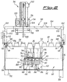
- the walls of the recesses 30 can house devices for conditoning the solutions in the bottles 34, such as heaters and/or refrigerators controlled by thermostats or cryostats, respectively, while a bottom 40 thereof further to operate as a support for the modular baskets 32 themselves, can be equipped with magnetically coupled actuators for providing stirring and mixing to solutions within the bottles 34 themselves, as herebelow disclosed in more detail particularly referring to figure 2.
- the table 12 comprises a metal sheet box 50 formed by a bottom 52 and two lateral walls 54 and 56 upwards terminated by edges 58 and 60 inside folded and supporting the two rails 14 and 16.
- the already mentioned bottom 40 divides the box 50 in an upper space, corresponding to the tub recesses 30, and a lower space 62 having the task of housing equipments such as for example heaters or refrigerators, or mechanical actuators for mixing and stirring liquid solutions into the bottles, such as the one visible both in figure 1 and 2 consisting, in particular of an electric motor 64 having connected to the shaft thereof a pulley 66 with two races, provided on the top with a pair of permanent magnets 68 and 70, justappointed under one of the bottles 34 housed in the modular basket 32, from where moves in rotation a stirrer 72 housed in the bottle 34 and consisting, as it is widely known in this art, of a small armature of ferromagnetic material, such as soft iron, suitably coated with a material inert and not reactive with respect to the solutions
- the stirrer 72 by rotating into the liquid bulk 74 contained in the bottle 34, moves it according to the curved arrow 76, providing a continuous mixing of the liquid solution.
- the two races of the pulley 66 house two respective belts 78 and 80 transmitting the movement of the moving pulley 66 to two adjacent idle pulleys 82 and 84, respectively, freely rotating on fixed shafts, such as the fixed shaft 86 visible in figure 2, and also provided with pairs of permanent magnets 78 and 80 for transmitting movement to the respective stirrers in the adjacent bottles 34.
- pulleys 82 and 84 can be engaged further transmission belts 88 and 90 transmitting the movement to as many pulleys as they are the bottles contained in any modular basket 32 for allowing the mixing of the solution contained in any bottle 34.
- the pulleys are in number equal to the bottles houseable in any modular basket 32, allowing the mixing of the solutions contained in any bottle. It is to intend that, if it is not desired to mix a solution housed in a bottle, it is sufficient not to provide the bottle with the strirrer 72.
- the table 12 can be provided with legs such as uprights 92 and 94.
- the means allowing the movement of a metering head 96 between the bottles 34 and the beakers 22 and 24 or between the beakers and the cleaning assemblies 28a-c are provided by a bridge 98 formed by two vertical uprights 100 and 102 connected by a cross member 104 and downwards provided with wheels 106 and 108 movable along the rails 14 and 16, where, for example, the wheel 106 is moved through some transmission means, such as a toothed belt or a chain 110, by a motor 112 fastened to the upright 100.
- the metering head 96 is substantially the same head described and claimed in the above mentioned European patent application to which reference is made for a detailed decription thereof.
- the alignment position of the metering head 96 with respect to the bottles 34 or the beakers 22, 24 and specifically of a syringe 120 providing the requested volumetric metering occurs through control means directed by a microprocessor (not shown) actuating the two respective motors 112 and 116 and receives position information from two position sensors 122 and 124 detecting the position of the bridge 98 on the rail 14 and the position of the metering head 96 on the cross member 104, respectively, being said position sensors, for example, proximity detectors of magnetic kind sensing the magnetic permeability change of the references 126 and 128 mounted on the rail 14 and the cross member 104, respectively.
- the references 126 and 128 could be simple holes through them left empty o filled with a plug of not ferromagnetic material, such as a not magnetic metal or, still better, a plastic not magnetic and insulating material.
- position sensors 122 and 124 can be taken into consideration, as position sensors 122 and 124, well known sensors based on other principles, such as for example, capacitive detectors sensing the electric capacity between their probes and said metallic rail 14 or cross member 104, sensing for example references 126 and 128 consisting of holes through the rail or the cross member themselves.
- said basket 18 for beakers, of course completely similar to the modular basket 20, it is seen that said basket 18 consists of two boards 130 and 132 each other connected by a support plane 134 and by a plate 136 provided with holes for housing the beakers 22, said boards 130 and 132 being provided with two handles 138 and 140 to allow an easy catching of the basket 18 for the movement thereof.
- anyone of the modular baskets 32 for the bottles 34 consits of a box 142, open on the top, and provided with two handles 144 and 146 for its lifting and movement.
- the operation of the invention is the following: when dye recipes are to be prepared through volumetric metering, one or more modular baskets 18 and/or 20 for beakers are placed on the left end area of the planar table 12 by lowering them in proper seats obviously provided on said table 12.
- One or more cleaning assemblies 28a-c are placed in the intermediate area between the place of the baskets 18 and 20 and the tub recesses 30 housing modular baskets 32 for bottles 34 of dyeing solutions.
- a number of baskets 32 is loaded in the recesses 30 (one to five in the case of the embodiment depicted in figure 1).
- the movable bridge 98 is moved to a preselected position corresponding to a modular basket and a row to which belongs the specific bottle 34 from which is to be taken a solution to be used in the recipe to be prepared.
- the particular modular basket and the row in the preselected basket are specified by data indicated by an electronic processor (not shown) and compared with position information along for example the rail 14 from the position sensor 122 sensing the references 126 placed on the rail 14 itself.
- position information along for example the rail 14 from the position sensor 122 sensing the references 126 placed on the rail 14 itself.
- the particular bottle 34 in the row of the preselected modular basket 32 It is just sufficient to move the metering head 96 to have the syringe 120 on the preselected bottle 34.
- To this purpose operates the above mentioned electronic processor with the help of the position sensor 124 sensing the references 128.
- the syringe 120 When a first dose of solution has been drawn by the syringe 120, according to a process already disclosed in the above mentioned European patent application, the syringe 120 is moved over the preselected of the beakers 22 or 24 into one of the modular baskets 18 or 20.
- the bridge 98 is moved to bring the syringe 120 itself over one of the rows of beakers 22 or 24, availing of the control of the above mentioned processor, the sensor 122 and the position references 126 corresponding to the preselected beaker row, then the metering head 96 is moved along the bridge 98 to bring the syringe 120 over the desired beaker, availing of the control of the electronic processor, the position sensor 124 and the position references 128 on the cross member 104 of the bridge 98 to bring the syringe 120 over the preselected of the beakers 22 or 24.
- the bridge 98 is moved to bring the the syringe 120 over one of the cleaning assemblies 28a-c, always availing of the control of the processor, the position sensors 122 and 124 and the references 126 and 128.
- the syringe 120 is lowered into the preselected assembly 28a-c and, actuating the piston of the syringe, as much detersive liquid is passed into the syringe as it is sufficient to clean it.
- the proportioner is ready to resume its operation.
Landscapes
- Chemical & Material Sciences (AREA)
- Chemical Kinetics & Catalysis (AREA)
- Analytical Chemistry (AREA)
- Pathology (AREA)
- Physics & Mathematics (AREA)
- Biochemistry (AREA)
- General Health & Medical Sciences (AREA)
- General Physics & Mathematics (AREA)
- Immunology (AREA)
- Life Sciences & Earth Sciences (AREA)
- Engineering & Computer Science (AREA)
- Textile Engineering (AREA)
- Health & Medical Sciences (AREA)
- Sampling And Sample Adjustment (AREA)
- Investigating Or Analysing Biological Materials (AREA)
- Catching Or Destruction (AREA)
- Automatic Analysis And Handling Materials Therefor (AREA)
- Medical Preparation Storing Or Oral Administration Devices (AREA)
Applications Claiming Priority (2)
| Application Number | Priority Date | Filing Date | Title |
|---|---|---|---|
| IT92MI001064U IT227060Y1 (it) | 1992-12-15 | 1992-12-15 | Perfezionato dosatore volumetrico munito di pipetta mobile lungo due dimensioni di un piano e di cestelli modulari |
| ITMI921064U | 1992-12-15 |
Publications (2)
| Publication Number | Publication Date |
|---|---|
| EP0602737A1 true EP0602737A1 (fr) | 1994-06-22 |
| EP0602737B1 EP0602737B1 (fr) | 1997-07-23 |
Family
ID=11363182
Family Applications (1)
| Application Number | Title | Priority Date | Filing Date |
|---|---|---|---|
| EP93203488A Expired - Lifetime EP0602737B1 (fr) | 1992-12-15 | 1993-12-11 | Mélangeur volumétrique proportionnel avec seringue mobile selon deux directions d'un plan et paniers modulaires pour récipients |
Country Status (4)
| Country | Link |
|---|---|
| EP (1) | EP0602737B1 (fr) |
| AT (1) | ATE155708T1 (fr) |
| DE (1) | DE69312438D1 (fr) |
| IT (1) | IT227060Y1 (fr) |
Cited By (12)
| Publication number | Priority date | Publication date | Assignee | Title |
|---|---|---|---|---|
| EP0897031A2 (fr) * | 1997-08-14 | 1999-02-17 | Tecnorama S.r.l. | Dispositif automatique de teinture des matières textiles |
| WO2000054875A1 (fr) * | 1999-03-17 | 2000-09-21 | Enrica Somenzi | Dispositif de delivrance et de distribution de couleurs ou de composes chimiques en general |
| EP1174535A2 (fr) * | 2000-07-06 | 2002-01-23 | TECNORAMA S.r.l. | Appareil pour la préparation automatique des solutions |
| WO2002005939A1 (fr) * | 2000-07-18 | 2002-01-24 | Basf Aktiengesellschaft | Procede et dispositif permettant la production et la caracterisation automatique de systemes liquides a plusieurs composantes |
| WO2003084653A1 (fr) * | 2002-04-03 | 2003-10-16 | E.I. Du Pont De Nemours And Company | Appareil de distribution |
| US6827478B2 (en) | 2000-07-18 | 2004-12-07 | Basf Aktiengesellschaft | Method and device for carrying out the automated preparation and characterization of liquid multi-constituent systems |
| CN1299812C (zh) * | 2001-08-14 | 2007-02-14 | 泰克诺拉玛有限责任公司 | 自动制备溶液的装置和测量液、固制品和溶液的组合系统 |
| EP2858043A1 (fr) * | 2013-10-01 | 2015-04-08 | meamix GmbH | Machine de remplissage de produits liquides et coulants |
| IT201900006584A1 (it) | 2019-05-07 | 2020-11-07 | Tecnorama Srl | Apparecchiatura per il prelievo e l’erogazione controllata di liquidi con dosaggio volumetrico. |
| WO2020240722A1 (fr) * | 2019-05-29 | 2020-12-03 | 株式会社日立ハイテク | Dispositif d'analyse |
| CN113967169A (zh) * | 2021-11-10 | 2022-01-25 | 珠海格力智能装备有限公司 | 一种自动配药液设备 |
| CN114887527A (zh) * | 2022-06-01 | 2022-08-12 | 贵州理工学院 | 一种羊肚菌酱加工用混合装置及方法 |
Citations (5)
| Publication number | Priority date | Publication date | Assignee | Title |
|---|---|---|---|---|
| GB2146619A (en) * | 1983-08-12 | 1985-04-24 | Sakata Shokai Ltd | Automatic dispensing system |
| US4967933A (en) * | 1989-02-27 | 1990-11-06 | Asymptotic Technologies, Inc. | Method and apparatus for dispensing viscous materials |
| US5055263A (en) * | 1988-01-14 | 1991-10-08 | Cyberlab, Inc. | Automated pipetting system |
| EP0454040A2 (fr) * | 1990-04-26 | 1991-10-30 | ELETTROMECCANICA SALCE SAS DI SALCE GIAN PIETRO & C. | Mélangeur volumétrique proportionnel, en particulier pour la préparation de teinture pour teinture industrielle |
| EP0555739A1 (fr) * | 1992-02-13 | 1993-08-18 | F. Hoffmann-La Roche Ag | Dispositif automatique de pipettage |
-
1992
- 1992-12-15 IT IT92MI001064U patent/IT227060Y1/it active IP Right Grant
-
1993
- 1993-12-11 EP EP93203488A patent/EP0602737B1/fr not_active Expired - Lifetime
- 1993-12-11 DE DE69312438T patent/DE69312438D1/de not_active Expired - Lifetime
- 1993-12-11 AT AT93203488T patent/ATE155708T1/de not_active IP Right Cessation
Patent Citations (5)
| Publication number | Priority date | Publication date | Assignee | Title |
|---|---|---|---|---|
| GB2146619A (en) * | 1983-08-12 | 1985-04-24 | Sakata Shokai Ltd | Automatic dispensing system |
| US5055263A (en) * | 1988-01-14 | 1991-10-08 | Cyberlab, Inc. | Automated pipetting system |
| US4967933A (en) * | 1989-02-27 | 1990-11-06 | Asymptotic Technologies, Inc. | Method and apparatus for dispensing viscous materials |
| EP0454040A2 (fr) * | 1990-04-26 | 1991-10-30 | ELETTROMECCANICA SALCE SAS DI SALCE GIAN PIETRO & C. | Mélangeur volumétrique proportionnel, en particulier pour la préparation de teinture pour teinture industrielle |
| EP0555739A1 (fr) * | 1992-02-13 | 1993-08-18 | F. Hoffmann-La Roche Ag | Dispositif automatique de pipettage |
Cited By (19)
| Publication number | Priority date | Publication date | Assignee | Title |
|---|---|---|---|---|
| EP0897031A3 (fr) * | 1997-08-14 | 2000-05-03 | Tecnorama S.r.l. | Dispositif automatique de teinture des matières textiles |
| EP0897031A2 (fr) * | 1997-08-14 | 1999-02-17 | Tecnorama S.r.l. | Dispositif automatique de teinture des matières textiles |
| WO2000054875A1 (fr) * | 1999-03-17 | 2000-09-21 | Enrica Somenzi | Dispositif de delivrance et de distribution de couleurs ou de composes chimiques en general |
| EP1174535A3 (fr) * | 2000-07-06 | 2003-12-17 | TECNORAMA S.r.l. | Appareil pour la préparation automatique des solutions |
| EP1174535A2 (fr) * | 2000-07-06 | 2002-01-23 | TECNORAMA S.r.l. | Appareil pour la préparation automatique des solutions |
| US6827478B2 (en) | 2000-07-18 | 2004-12-07 | Basf Aktiengesellschaft | Method and device for carrying out the automated preparation and characterization of liquid multi-constituent systems |
| WO2002005939A1 (fr) * | 2000-07-18 | 2002-01-24 | Basf Aktiengesellschaft | Procede et dispositif permettant la production et la caracterisation automatique de systemes liquides a plusieurs composantes |
| CN1299812C (zh) * | 2001-08-14 | 2007-02-14 | 泰克诺拉玛有限责任公司 | 自动制备溶液的装置和测量液、固制品和溶液的组合系统 |
| WO2003084653A1 (fr) * | 2002-04-03 | 2003-10-16 | E.I. Du Pont De Nemours And Company | Appareil de distribution |
| US6769462B2 (en) | 2002-04-03 | 2004-08-03 | E. I. Du Pont De Nemours And Company | Dispensing apparatus |
| EP2858043A1 (fr) * | 2013-10-01 | 2015-04-08 | meamix GmbH | Machine de remplissage de produits liquides et coulants |
| WO2020225836A1 (fr) | 2019-05-07 | 2020-11-12 | Tecnorama S.R.L. | Équipement pour la collecte et l'administration contrôlée de liquides à dosage volumétrique |
| IT201900006584A1 (it) | 2019-05-07 | 2020-11-07 | Tecnorama Srl | Apparecchiatura per il prelievo e l’erogazione controllata di liquidi con dosaggio volumetrico. |
| WO2020240722A1 (fr) * | 2019-05-29 | 2020-12-03 | 株式会社日立ハイテク | Dispositif d'analyse |
| JPWO2020240722A1 (fr) * | 2019-05-29 | 2020-12-03 | ||
| JP7142775B2 (ja) | 2019-05-29 | 2022-09-27 | 株式会社日立ハイテク | 分析装置 |
| CN113967169A (zh) * | 2021-11-10 | 2022-01-25 | 珠海格力智能装备有限公司 | 一种自动配药液设备 |
| CN114887527A (zh) * | 2022-06-01 | 2022-08-12 | 贵州理工学院 | 一种羊肚菌酱加工用混合装置及方法 |
| CN114887527B (zh) * | 2022-06-01 | 2023-11-24 | 贵州理工学院 | 一种羊肚菌酱加工用混合装置及方法 |
Also Published As
| Publication number | Publication date |
|---|---|
| ATE155708T1 (de) | 1997-08-15 |
| ITMI921064V0 (it) | 1992-12-15 |
| DE69312438D1 (de) | 1997-09-04 |
| EP0602737B1 (fr) | 1997-07-23 |
| ITMI921064U1 (it) | 1994-06-15 |
| IT227060Y1 (it) | 1997-09-09 |
Similar Documents
| Publication | Publication Date | Title |
|---|---|---|
| EP0602737B1 (fr) | Mélangeur volumétrique proportionnel avec seringue mobile selon deux directions d'un plan et paniers modulaires pour récipients | |
| US5096670A (en) | Automated patient sample analysis instrument | |
| USRE41760E1 (en) | Bi-directional magnetic sample rack conveying system | |
| EP0563893B1 (fr) | Appareil pour aspirer et distribuer des liquides | |
| CA1282692C (fr) | Appareil automatique pour le dosage des antigenes ou des anticorps dans les liquides biologiques | |
| CN104483499A (zh) | 全自动特定蛋白分析仪 | |
| EP0672255A1 (fr) | Procede et dispositif automatise pour la realisation de tests immunologiques | |
| JPH07181188A (ja) | 分析装置 | |
| CN109116013A (zh) | 一种多重免疫分析仪 | |
| EP0563891A2 (fr) | Appareil automatique d'analyse immunochimique | |
| US20040042339A1 (en) | Method and apparatus for mixing liquid samples using a sinusoidal mixing action | |
| ES2255091T3 (es) | Metodo de funcionamiento de diferentes aparatos para realizar un procedimiento. | |
| CN101213012B (zh) | 用来移动液体容器的装置和方法 | |
| CN111044742A (zh) | 一种智能型样品处理检测装置 | |
| CN208345082U (zh) | 连续式升降机 | |
| JPH04235352A (ja) | 液体充填容器の搬送装置 | |
| JP2549988B2 (ja) | 液体計量採取装置 | |
| CN115541914A (zh) | 一种金标仪用加样检测机构 | |
| CN211877210U (zh) | 一种自动称重配料装置 | |
| JPH0968536A (ja) | 自動分析装置 | |
| US3852035A (en) | Automated handling and treating apparatus | |
| CN113092222B (zh) | 一种染色仪的染色装置 | |
| CN220282747U (zh) | 运杯器全域运行装置 | |
| JP3231222B2 (ja) | 分注装置 | |
| KR100317753B1 (ko) | 실험실용 염료 정량 투입장치 |
Legal Events
| Date | Code | Title | Description |
|---|---|---|---|
| PUAI | Public reference made under article 153(3) epc to a published international application that has entered the european phase |
Free format text: ORIGINAL CODE: 0009012 |
|
| AK | Designated contracting states |
Kind code of ref document: A1 Designated state(s): AT BE CH DE ES FR GB GR IT LI NL PT |
|
| 17P | Request for examination filed |
Effective date: 19941214 |
|
| 17Q | First examination report despatched |
Effective date: 19960115 |
|
| GRAG | Despatch of communication of intention to grant |
Free format text: ORIGINAL CODE: EPIDOS AGRA |
|
| GRAH | Despatch of communication of intention to grant a patent |
Free format text: ORIGINAL CODE: EPIDOS IGRA |
|
| RHK1 | Main classification (correction) |
Ipc: B01F 13/10 |
|
| GRAH | Despatch of communication of intention to grant a patent |
Free format text: ORIGINAL CODE: EPIDOS IGRA |
|
| GRAA | (expected) grant |
Free format text: ORIGINAL CODE: 0009210 |
|
| AK | Designated contracting states |
Kind code of ref document: B1 Designated state(s): AT BE CH DE ES FR GB GR IT LI NL PT |
|
| PG25 | Lapsed in a contracting state [announced via postgrant information from national office to epo] |
Ref country code: NL Free format text: LAPSE BECAUSE OF FAILURE TO SUBMIT A TRANSLATION OF THE DESCRIPTION OR TO PAY THE FEE WITHIN THE PRESCRIBED TIME-LIMIT Effective date: 19970723 Ref country code: LI Effective date: 19970723 Ref country code: IT Free format text: LAPSE BECAUSE OF FAILURE TO SUBMIT A TRANSLATION OF THE DESCRIPTION OR TO PAY THE FEE WITHIN THE PRE;WARNING: LAPSES OF ITALIAN PATENTS WITH EFFECTIVE DATE BEFORE 2007 MAY HAVE OCCURRED AT ANY TIME BEFORE 2007. THE CORRECT EFFECTIVE DATE MAY BE DIFFERENT FROM THE ONE RECORDED.SCRIBED TIME-LIMIT Effective date: 19970723 Ref country code: GR Free format text: LAPSE BECAUSE OF FAILURE TO SUBMIT A TRANSLATION OF THE DESCRIPTION OR TO PAY THE FEE WITHIN THE PRESCRIBED TIME-LIMIT Effective date: 19970723 Ref country code: FR Effective date: 19970723 Ref country code: ES Free format text: THE PATENT HAS BEEN ANNULLED BY A DECISION OF A NATIONAL AUTHORITY Effective date: 19970723 Ref country code: CH Effective date: 19970723 Ref country code: BE Effective date: 19970723 Ref country code: AT Effective date: 19970723 |
|
| REF | Corresponds to: |
Ref document number: 155708 Country of ref document: AT Date of ref document: 19970815 Kind code of ref document: T |
|
| REG | Reference to a national code |
Ref country code: CH Ref legal event code: EP |
|
| REF | Corresponds to: |
Ref document number: 69312438 Country of ref document: DE Date of ref document: 19970904 |
|
| PG25 | Lapsed in a contracting state [announced via postgrant information from national office to epo] |
Ref country code: DE Effective date: 19971024 |
|
| PG25 | Lapsed in a contracting state [announced via postgrant information from national office to epo] |
Ref country code: PT Effective date: 19971031 |
|
| PG25 | Lapsed in a contracting state [announced via postgrant information from national office to epo] |
Ref country code: GB Free format text: LAPSE BECAUSE OF NON-PAYMENT OF DUE FEES Effective date: 19971211 |
|
| EN | Fr: translation not filed | ||
| NLV1 | Nl: lapsed or annulled due to failure to fulfill the requirements of art. 29p and 29m of the patents act | ||
| REG | Reference to a national code |
Ref country code: CH Ref legal event code: PL |
|
| PLBE | No opposition filed within time limit |
Free format text: ORIGINAL CODE: 0009261 |
|
| STAA | Information on the status of an ep patent application or granted ep patent |
Free format text: STATUS: NO OPPOSITION FILED WITHIN TIME LIMIT |
|
| 26N | No opposition filed | ||
| GBPC | Gb: european patent ceased through non-payment of renewal fee |
Effective date: 19971211 |