EP0602590A1 - Rear fender for motor-bicyle - Google Patents
Rear fender for motor-bicyle Download PDFInfo
- Publication number
- EP0602590A1 EP0602590A1 EP93120126A EP93120126A EP0602590A1 EP 0602590 A1 EP0602590 A1 EP 0602590A1 EP 93120126 A EP93120126 A EP 93120126A EP 93120126 A EP93120126 A EP 93120126A EP 0602590 A1 EP0602590 A1 EP 0602590A1
- Authority
- EP
- European Patent Office
- Prior art keywords
- container
- fender
- buttery
- box
- rear fender
- Prior art date
- Legal status (The legal status is an assumption and is not a legal conclusion. Google has not performed a legal analysis and makes no representation as to the accuracy of the status listed.)
- Granted
Links
Images


Classifications
-
- B—PERFORMING OPERATIONS; TRANSPORTING
- B62—LAND VEHICLES FOR TRAVELLING OTHERWISE THAN ON RAILS
- B62K—CYCLES; CYCLE FRAMES; CYCLE STEERING DEVICES; RIDER-OPERATED TERMINAL CONTROLS SPECIALLY ADAPTED FOR CYCLES; CYCLE AXLE SUSPENSIONS; CYCLE SIDE-CARS, FORECARS, OR THE LIKE
- B62K19/00—Cycle frames
- B62K19/46—Luggage carriers forming part of frame
-
- B—PERFORMING OPERATIONS; TRANSPORTING
- B62—LAND VEHICLES FOR TRAVELLING OTHERWISE THAN ON RAILS
- B62J—CYCLE SADDLES OR SEATS; AUXILIARY DEVICES OR ACCESSORIES SPECIALLY ADAPTED TO CYCLES AND NOT OTHERWISE PROVIDED FOR, e.g. ARTICLE CARRIERS OR CYCLE PROTECTORS
- B62J15/00—Mud-guards for wheels
Definitions
- the present invention relates to a rear fender for a motor-bicycle which is formed integrally with a container and is dividable in the longitudinal direction.
- Japanese utility Model Laid-open No. HEI 1-161888 shows a rear fender for a motor-bicycle dividable in the longitudinal direction.
- the rear fender is formed integrally with a buttery box as a container at a front end portion, and includes a curved surface opposed to the upper portion of a rear wheel outer periphery as a fender portion, wherein the fender portion is divided in the longitudinal direction at the portion near the upper end portion of the rear wheel equivalent to an approximately intermediate portion.
- a fender portion has a fear to be damaged through the collision of a small stone jumped by a rear wheel during running, which often brings about the necessity of the exchange of the rear fender.
- the buttery box being relatively less susceptible to damage must be also exchanged as one-body. This is uneconomical.
- an object of the present invention is to solve the above problem.
- a rear fender for a motor-bicycle including a curved surface opposed to the upper portion of a rear wheel outer periphery, and a container integrally formed at a front end portion thereof, wherein the rear fender is dividable in the longitudinal direction, characterized in that the rear fender is dividable into a container at least a part of the container formed at the front end, and a fender portion containing the whole length of the curved surface at the rear portion.
- the rear fender is divided in the container portion and the fender portion, so that a portion relatively susceptible to damage is separated from a portion relatively less susceptible to damage.
- the fender portion is damaged, only the fender portion is exchanged while leaving the container portion.
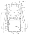
- Fig. 2 shows shapes of essential parts on the side surface of a motor-bicycle.
- a front fork 3 is supported through a head pipe 2.
- a front wheel 4 is supported on the lower end portion of the main frames 1.
- Pivot frames 5 are coupled to the rear portions of the main frames 2, and a rear wheel 7 is supported on the rear end portions of rear arms 6 pivotably supported at the front ends by the pivot frames 5.
- a seat 9 is supported on a pair of right and left seat rails 8 extending obliquely, upward and rearward from the rear portions of the main frames 1.
- a rear fender 10 is supported on the seat rails 8 while crossing the seat rails 8 and a rear stay 11 provided under the seat rails 8.
- Fig. 1 is a view showing shapes of essential parts on the side surface of the rear fender, with parts being partially cut-away, wherein a buttery box 12 is formed at the front end portion of the rear fender 10. A container 13 opened upward is continuously formed in the back of the buttery box 12.
- the container 13 is divided in the longitudinal direction at a division line 14 of an intermediate portion.
- a container front portion 13a is integrated with the buttery box 12, which constitute the container portion of the present invention.
- a container rear portion 13b is integrated with a fender portion 15 formed rearwardly of the container front portion 13a, which constitute the front end portion.
- the fender portion 15 is a member for covering the outside of the rear wheel 7, and is a portion formed with a curved portion 16 opposed to the upper portion of the outer periphery of the rear wheel 7.
- the rear end portion of the fender portion 15 extends up to an uppermost position of the rear wheel 7, and a boss 17 projects upward from the upper portion of the rear end portion, on which an insert nut 18 is provided.
- the boss 17 is abutted on a cross plate 19 crossing between the right and left seat rails 8, and the rear end portion of the fender portion 15 is supported on the seat rails 8 side by fastening of a bolt 20 and the insert nut 18.
- Fig. 3 is a view of the rear fender taken along the direction of the arrow A of Fig. 1; and Fig. 4 is a view of the rear fender taken along the direction of the arrow B of Fig. 1.
- Fig. 5 is a view showing the state where the container portion including the buttery box 12 is separated from the fender portion 15.
- the buttery box 12 projects forward from a front wall 21 of the container front portion 13a, and the upper side of the projection portion is covered with a ceiling portion 22.
- a pair of right and left hooks 23 are provided on the connection portion between the ceiling portion 22 and the front wall 21.
- An engaging groove 24 opened forward in the horizontal direction is provided on the hook 23 (see Figs. 1 and 5), and which is engaged with each of supporting members 25 mounted on the seat rails 8 (see Figs. 1 and 3).
- Reference numeral 26 indicates a coupling piece provided so as to project forward from the buttery box 12.
- the interior of the buttery box 12 and the container front portion 13a is partitioned by a pressing plate 27, and a buttery BT is contained in a space formed forwardly of the pressing plate 27.
- the upper end portion of the pressing plate 27 is mounted to the front wall 21 by means of a bolt/nut 28 and the like.
- the lower end portion of the pressing plate 27 is inserted in a hole 29 formed on the bottom portion of the boundary portion between the buttery box 12 and the container front portion 13a (see Fig. 3, which shows the state where the pressing plate 27 is not mounted).
- the side surfaces of the rear end portion of the container front portion 13a and the front end portion of the container rear portion 13b are provided with flanges 31 and 32 along the division line 14.
- the flanges 31 and 32 are connected to each other such that the opposed faces thereof are mated, and which are joined to each other at vertical suitable points along the division line 14 by means of a plurality of clips 33.
- a projection 34 projecting to the flange 32 side beyond the division line 14 is formed at each portion of the the flange 31 where the clip 33 is provided. Further, a hole 35 to be fitted with the projection 34 is formed on the flange 32 side.
- a leaf spring approximately C-shaped in section is suitable used as the clip 33.
- a positioning projection 36 for preventing the vertical shift of the clip 33 is formed on each portion of the flange 31 where the clip 33 is provided.
- a projection 37 and a hole 38 to be fitted to each other are respectively formed on the upper end portions of the flange 31 and the flange 32 along the division line 14, while being not the portions where the clips are provided.
- projections 39 and 40 projecting downward are provided on the lower end portions of the flanges 31 and 32 along the division line 14.
- the projections 39 and 40, and further, the upper end portion of a mud guard 41 are mated and fastened by means of a tapping screw 42, thus being joined integrally to each other.
- the wall portion 43 comprising the rear portion and the bottom portion of the container rear portion 13b is formed of the front portion of the curved surface portion 16 itself. As shown in Fig. 1, this enables the buttery BT to come in and out of the buttery box 12 by making slant the buttery BT along the curved surface of the wall portion 43. At this time, the pressing plate 27 is previously removed.
- the clips 33 are removed, the container front portion 13a is separated from the container rear portion 13b at the division line 14, so that the container portion including the buttery box 12 is divided from the fender portion 15, which makes it possible to exchange only the fender portion 15 while leaving ther container portion.
- the fender portion 15 relatively susceptible to damage is separated from a container portion relatively less liable to damage, and are separately exchanged, resulting in the improved economical effect. Further, since the fender portion 15 and the container portion are connected to each other by the clips 33, it is possible to simply and rapidly perform the dividing and re-coupling work.
- the flange 31 of the remaining container portion and the flange 32 of the exchanged fender portion 15 are mated to each other, and are coupled to each other by fitting of the projections 34 of the flange 31 to the holes 32 of the flange 32, and further, are joined to each other by the clips 33.
- the rear fender 10 comprising the container portion including the buttery box 12 integrated with the new fender portion 15 is formed, which is mounted to the vehicular body in the reversed manner.
- the container portion and the fender portion 15 are previously integrated with each other, it is possible to simply and rapidly perform the mounting work. Further, the same is true for the exchange of the buttery box 12 side.
- the present invention is not limited to the above embodiment, and various modifications are possible.
- the container front portion 13a may be enlarged, and the container rear portion 13b is provided on the fender portion 15 side.
- the container 15 may be omitted, and the rear fender 10 may be constituted of only the buttery box 12 and the fender portion 15.
- the container different from the buttery box 12 and the container 13 may be freely formed on the intermediate portion of the fender portion 15.
- the rear fender of a motor-bicycle according to the present invention is divided in the container portion and the fender portion, and the fender portion includes the whole length of the curved surface opposed to the outer periphery of the rear wheel, the portion relatively susceptible to damage is easily separated from the portion relatively less susceptible to damage. Accordingly, in exchange of the fender portion or the container portion, only either the fender portion or the container portion can be exchanged, while the other being left, which is extremely economical.
Abstract
[Construction] A rear fender 10 is dividable in a container portion on the front side and a fender portion 15 on the rear side. The container portion includes a buttery box 12 integrally formed on the front end portion and a container front portion 13a constituting the front half of a container 13. The fender portion 15 includes a container rear portion 13b constituting the rear half portion of the container 13 and the whole length of a curved surface 16. The container front portion 13a and the container rear portion 13b are mated and connected to each other at a division line 14, which are joined to each other by clips 33. This makes it possible to separate the fender portion 15 relatively high in the necessity of the exchange from the container portion not relatively high in the necessity of the exchange.
Description
- The present invention relates to a rear fender for a motor-bicycle which is formed integrally with a container and is dividable in the longitudinal direction.
- Japanese utility Model Laid-open No. HEI 1-161888 shows a rear fender for a motor-bicycle dividable in the longitudinal direction. The rear fender is formed integrally with a buttery box as a container at a front end portion, and includes a curved surface opposed to the upper portion of a rear wheel outer periphery as a fender portion, wherein the fender portion is divided in the longitudinal direction at the portion near the upper end portion of the rear wheel equivalent to an approximately intermediate portion.
- In general, a fender portion has a fear to be damaged through the collision of a small stone jumped by a rear wheel during running, which often brings about the necessity of the exchange of the rear fender. However, when the front half side of the fender portion is required to be exchanged in the above structure, the buttery box being relatively less susceptible to damage must be also exchanged as one-body. This is uneconomical.
- On the contrary, when only the buttery box is damaged by any cause, the fender portion must be exchanged as one-body. This is similarly uneconomical. The same is true for the common container, the application of which is not limited to the buttery box. Accordingly, an object of the present invention is to solve the above problem.
- To achieve the above problem, according to the present invention, there is provided a rear fender for a motor-bicycle including a curved surface opposed to the upper portion of a rear wheel outer periphery, and a container integrally formed at a front end portion thereof, wherein the rear fender is dividable in the longitudinal direction, characterized in that the rear fender is dividable into a container at least a part of the container formed at the front end, and a fender portion containing the whole length of the curved surface at the rear portion.
- Since the fender portion includes the whole length of the curved surface, the rear fender is divided in the container portion and the fender portion, so that a portion relatively susceptible to damage is separated from a portion relatively less susceptible to damage. Thus, when the fender portion is damaged, only the fender portion is exchanged while leaving the container portion.
- One embodiment will be described with reference to Figs. 1 to 6. First, Fig. 2 shows shapes of essential parts on the side surface of a motor-bicycle. On the front end portions of a pair of main frames 1 extending in the longitudinal direction, a front fork 3 is supported through a head pipe 2. Further, a front wheel 4 is supported on the lower end portion of the main frames 1.
-
Pivot frames 5 are coupled to the rear portions of the main frames 2, and arear wheel 7 is supported on the rear end portions of rear arms 6 pivotably supported at the front ends by thepivot frames 5. Aseat 9 is supported on a pair of right andleft seat rails 8 extending obliquely, upward and rearward from the rear portions of the main frames 1. - Under the
seat 9, arear fender 10 is supported on theseat rails 8 while crossing theseat rails 8 and arear stay 11 provided under theseat rails 8. - Fig. 1 is a view showing shapes of essential parts on the side surface of the rear fender, with parts being partially cut-away, wherein a
buttery box 12 is formed at the front end portion of therear fender 10. Acontainer 13 opened upward is continuously formed in the back of thebuttery box 12. - The
container 13 is divided in the longitudinal direction at adivision line 14 of an intermediate portion. Acontainer front portion 13a is integrated with thebuttery box 12, which constitute the container portion of the present invention. A containerrear portion 13b is integrated with afender portion 15 formed rearwardly of thecontainer front portion 13a, which constitute the front end portion. - The
fender portion 15 is a member for covering the outside of therear wheel 7, and is a portion formed with acurved portion 16 opposed to the upper portion of the outer periphery of therear wheel 7. The rear end portion of thefender portion 15 extends up to an uppermost position of therear wheel 7, and aboss 17 projects upward from the upper portion of the rear end portion, on which aninsert nut 18 is provided. - The
boss 17 is abutted on across plate 19 crossing between the right andleft seat rails 8, and the rear end portion of thefender portion 15 is supported on theseat rails 8 side by fastening of a bolt 20 and theinsert nut 18. - Fig. 3 is a view of the rear fender taken along the direction of the arrow A of Fig. 1; and Fig. 4 is a view of the rear fender taken along the direction of the arrow B of Fig. 1. Fig. 5 is a view showing the state where the container portion including the
buttery box 12 is separated from thefender portion 15. - In these figures, the
buttery box 12 projects forward from afront wall 21 of thecontainer front portion 13a, and the upper side of the projection portion is covered with aceiling portion 22. A pair of right andleft hooks 23 are provided on the connection portion between theceiling portion 22 and thefront wall 21. - An
engaging groove 24 opened forward in the horizontal direction is provided on the hook 23 (see Figs. 1 and 5), and which is engaged with each of supportingmembers 25 mounted on the seat rails 8 (see Figs. 1 and 3).Reference numeral 26 indicates a coupling piece provided so as to project forward from thebuttery box 12. - As is apparent from Fig. 5, the interior of the
buttery box 12 and thecontainer front portion 13a is partitioned by apressing plate 27, and a buttery BT is contained in a space formed forwardly of thepressing plate 27. - The upper end portion of the
pressing plate 27 is mounted to thefront wall 21 by means of a bolt/nut 28 and the like. The lower end portion of thepressing plate 27 is inserted in ahole 29 formed on the bottom portion of the boundary portion between thebuttery box 12 and thecontainer front portion 13a (see Fig. 3, which shows the state where thepressing plate 27 is not mounted). - As is apparent from Figs. 1 and 5, the side surfaces of the rear end portion of the
container front portion 13a and the front end portion of the containerrear portion 13b are provided withflanges division line 14. Theflanges division line 14 by means of a plurality ofclips 33. - As is apparent from Fig. 6 which is a sectional view taken along the line C-C, a
projection 34 projecting to theflange 32 side beyond thedivision line 14 is formed at each portion of the theflange 31 where theclip 33 is provided. Further, ahole 35 to be fitted with theprojection 34 is formed on theflange 32 side. - As the
clip 33, a leaf spring approximately C-shaped in section is suitable used. In addition, as is apparent from Fig. 5, apositioning projection 36 for preventing the vertical shift of theclip 33 is formed on each portion of theflange 31 where theclip 33 is provided. - As is apparent from Fig. 5, a
projection 37 and ahole 38 to be fitted to each other are respectively formed on the upper end portions of theflange 31 and theflange 32 along thedivision line 14, while being not the portions where the clips are provided. - As is apparent from Fig. 1,
projections flanges division line 14. Theprojections mud guard 41 are mated and fastened by means of a tappingscrew 42, thus being joined integrally to each other. - As is apparent from Figs. 1 and 5, the
wall portion 43 comprising the rear portion and the bottom portion of the containerrear portion 13b is formed of the front portion of thecurved surface portion 16 itself. As shown in Fig. 1, this enables the buttery BT to come in and out of thebuttery box 12 by making slant the buttery BT along the curved surface of thewall portion 43. At this time, thepressing plate 27 is previously removed. - Next, the function of the embodiment will be described. When the
fender portion 15 must be exchanged due to any cause, first, as shown in Fig. 1, by removing of the bolt 20 which mounts the rear portion of thefender portion 15, theboss 17 is separated from thecross plate 19, and by removing of thehooks 23 from the supportingmember 25, therear fender 10 is removed from the vehicular body. - Subsequently, the
clips 33 are removed, thecontainer front portion 13a is separated from the containerrear portion 13b at thedivision line 14, so that the container portion including thebuttery box 12 is divided from thefender portion 15, which makes it possible to exchange only thefender portion 15 while leaving ther container portion. - Accordingly, the
fender portion 15 relatively susceptible to damage is separated from a container portion relatively less liable to damage, and are separately exchanged, resulting in the improved economical effect. Further, since thefender portion 15 and the container portion are connected to each other by theclips 33, it is possible to simply and rapidly perform the dividing and re-coupling work. - After that, as shown in Fig. 5, the
flange 31 of the remaining container portion and theflange 32 of the exchangedfender portion 15 are mated to each other, and are coupled to each other by fitting of theprojections 34 of theflange 31 to theholes 32 of theflange 32, and further, are joined to each other by theclips 33. - Thus, the
rear fender 10 comprising the container portion including thebuttery box 12 integrated with thenew fender portion 15 is formed, which is mounted to the vehicular body in the reversed manner. At this time, since the container portion and thefender portion 15 are previously integrated with each other, it is possible to simply and rapidly perform the mounting work. Further, the same is true for the exchange of thebuttery box 12 side. - In addition, the present invention is not limited to the above embodiment, and various modifications are possible. For example, the
container front portion 13a may be enlarged, and the containerrear portion 13b is provided on thefender portion 15 side. Further, thecontainer 15 may be omitted, and therear fender 10 may be constituted of only thebuttery box 12 and thefender portion 15. The container different from thebuttery box 12 and thecontainer 13 may be freely formed on the intermediate portion of thefender portion 15. - Since the rear fender of a motor-bicycle according to the present invention is divided in the container portion and the fender portion, and the fender portion includes the whole length of the curved surface opposed to the outer periphery of the rear wheel, the portion relatively susceptible to damage is easily separated from the portion relatively less susceptible to damage. Accordingly, in exchange of the fender portion or the container portion, only either the fender portion or the container portion can be exchanged, while the other being left, which is extremely economical.
-
- [Fig. 1]
A view showing the side surface of essential parts according to the embodiment, with parts being cut-away. - [Fig. 2]
A side view of essential parts of a vehicular body of a motor-bicycle according to the embodiment. - [Fig. 3]
An enlarged view of the essential parts of the embodiment taken along the direction of the arrow A of Fig. 1. - [Fig. 4]
An enlarged view of the essential parts of the embodiment taken along the direction of the arrow B of Fig. 1. - [Fig. 5]
An exploded view of essential parts in the division portion according to the embodiment, with parts partially cut-away. - [Fig. 6]
A sectional view taken along the line C-C of Fig. 1 -
1 main frame, 7 rear wheel, 10 rear fender, 12 buttery box (container portion), 13 container, 13a container front portion (container portion), 13b container rear portion, 14 division line, 15 fender portion, 16 curved surface, 31, 32 flange, 33 clip, BT buttery
Claims (1)
- A rear fender for a motor-bicycle including a curved surface opposed to the upper portion of a rear wheel outer periphery, and a container integrally formed at a front end portion thereof, wherein said rear fender is dividable in the longitudinal direction, characterized in that
said rear fender is dividable into a container at least a part of said container formed at said front end, and a fender portion containing the whole length of said curved surface at the rear portion.
Applications Claiming Priority (2)
| Application Number | Priority Date | Filing Date | Title |
|---|---|---|---|
| JP354781/92 | 1992-12-17 | ||
| JP35478192A JP3285100B2 (en) | 1992-12-17 | 1992-12-17 | Rear fender of motorcycle |
Publications (2)
| Publication Number | Publication Date |
|---|---|
| EP0602590A1 true EP0602590A1 (en) | 1994-06-22 |
| EP0602590B1 EP0602590B1 (en) | 1997-04-16 |
Family
ID=18439864
Family Applications (1)
| Application Number | Title | Priority Date | Filing Date |
|---|---|---|---|
| EP19930120126 Expired - Lifetime EP0602590B1 (en) | 1992-12-17 | 1993-12-14 | Rear fender for motor-bicyle |
Country Status (4)
| Country | Link |
|---|---|
| EP (1) | EP0602590B1 (en) |
| JP (1) | JP3285100B2 (en) |
| BR (1) | BR9305066A (en) |
| DE (1) | DE69309869T2 (en) |
Cited By (2)
| Publication number | Priority date | Publication date | Assignee | Title |
|---|---|---|---|---|
| EP2703265A1 (en) * | 2012-08-31 | 2014-03-05 | Honda Motor Co., Ltd. | Rear portion structure for a saddle type vehicle |
| US11124260B2 (en) * | 2017-12-08 | 2021-09-21 | Kawasaki Jukogyo Kabushiki Kaisha | Saddle type vehicle |
Families Citing this family (7)
| Publication number | Priority date | Publication date | Assignee | Title |
|---|---|---|---|---|
| JP3699542B2 (en) * | 1996-09-11 | 2005-09-28 | 本田技研工業株式会社 | Storage structure for motorcycle rear fender |
| JP3814066B2 (en) * | 1997-12-09 | 2006-08-23 | 本田技研工業株式会社 | Seat lock device for motorcycle |
| JP4595530B2 (en) * | 2004-12-22 | 2010-12-08 | スズキ株式会社 | Motorcycle article storage device |
| JP5090838B2 (en) * | 2007-09-21 | 2012-12-05 | 川崎重工業株式会社 | Motorcycle rear fender assembly |
| JP5926653B2 (en) * | 2012-08-28 | 2016-05-25 | 本田技研工業株式会社 | Storage structure of saddle-ride type vehicle |
| JP5883765B2 (en) * | 2012-10-24 | 2016-03-15 | 本田技研工業株式会社 | Vehicle battery holder structure |
| CN105799821A (en) * | 2016-03-09 | 2016-07-27 | 力帆实业(集团)股份有限公司 | Rear-fender front body of motorcycle |
Citations (4)
| Publication number | Priority date | Publication date | Assignee | Title |
|---|---|---|---|---|
| GB660080A (en) * | 1949-12-14 | 1951-10-31 | Hugh Gordon Gwynn | A new or improved luggage carrier for motor cycles |
| GB717154A (en) * | 1952-06-18 | 1954-10-20 | Josef Jozif | An arrangement of the tool boxes on motor cycles |
| JPH01161888U (en) * | 1988-04-26 | 1989-11-10 | ||
| JPH0592784A (en) * | 1991-10-03 | 1993-04-16 | Suzuki Motor Corp | Mounting device of battery of motorcycle and portable tool |
-
1992
- 1992-12-17 JP JP35478192A patent/JP3285100B2/en not_active Expired - Fee Related
-
1993
- 1993-12-14 DE DE1993609869 patent/DE69309869T2/en not_active Expired - Fee Related
- 1993-12-14 EP EP19930120126 patent/EP0602590B1/en not_active Expired - Lifetime
- 1993-12-15 BR BR9305066A patent/BR9305066A/en not_active IP Right Cessation
Patent Citations (4)
| Publication number | Priority date | Publication date | Assignee | Title |
|---|---|---|---|---|
| GB660080A (en) * | 1949-12-14 | 1951-10-31 | Hugh Gordon Gwynn | A new or improved luggage carrier for motor cycles |
| GB717154A (en) * | 1952-06-18 | 1954-10-20 | Josef Jozif | An arrangement of the tool boxes on motor cycles |
| JPH01161888U (en) * | 1988-04-26 | 1989-11-10 | ||
| JPH0592784A (en) * | 1991-10-03 | 1993-04-16 | Suzuki Motor Corp | Mounting device of battery of motorcycle and portable tool |
Non-Patent Citations (1)
| Title |
|---|
| PATENT ABSTRACTS OF JAPAN vol. 17, no. 430 (M - 1460) 10 August 1993 (1993-08-10) * |
Cited By (4)
| Publication number | Priority date | Publication date | Assignee | Title |
|---|---|---|---|---|
| EP2703265A1 (en) * | 2012-08-31 | 2014-03-05 | Honda Motor Co., Ltd. | Rear portion structure for a saddle type vehicle |
| US8864157B2 (en) | 2012-08-31 | 2014-10-21 | Honda Motor Co., Ltd. | Rear portion structure for a saddle type vehicle |
| AU2013206646B2 (en) * | 2012-08-31 | 2016-02-25 | Honda Motor Co., Ltd. | Rear portion structure for a saddle type vehicle |
| US11124260B2 (en) * | 2017-12-08 | 2021-09-21 | Kawasaki Jukogyo Kabushiki Kaisha | Saddle type vehicle |
Also Published As
| Publication number | Publication date |
|---|---|
| DE69309869T2 (en) | 1997-07-24 |
| JP3285100B2 (en) | 2002-05-27 |
| JPH06183383A (en) | 1994-07-05 |
| BR9305066A (en) | 1994-08-16 |
| DE69309869D1 (en) | 1997-05-22 |
| EP0602590B1 (en) | 1997-04-16 |
Similar Documents
| Publication | Publication Date | Title |
|---|---|---|
| EP1095845A2 (en) | Structure of front end portion of front fender in vehicle | |
| EP0602590B1 (en) | Rear fender for motor-bicyle | |
| US4712637A (en) | Straddle type vehicle seat assembly | |
| JP2907502B2 (en) | How to assemble the front body of the vehicle | |
| JPS6315191B2 (en) | ||
| JPS62289449A (en) | Car bumper mounting structure | |
| JP3692280B2 (en) | Cover member mounting structure for vehicle roof groove | |
| JPS606362Y2 (en) | Bumper side mounting structure | |
| JPH106887A (en) | Front bumper structure for vehicle | |
| KR930000120Y1 (en) | Bumper | |
| JPH0530500Y2 (en) | ||
| JPH0236767Y2 (en) | ||
| KR0179739B1 (en) | Detachable fender apparatus | |
| JPS6320573Y2 (en) | ||
| JPH0443425Y2 (en) | ||
| JPH046990Y2 (en) | ||
| JP2877691B2 (en) | License plate frame | |
| KR960005310B1 (en) | Rear combinaton lamp bracket for fork lift | |
| JPH0260649U (en) | ||
| JP3485458B2 (en) | Headlamp cover for all-terrain vehicles | |
| JPH0528128Y2 (en) | ||
| JPS60996Y2 (en) | Structure of the headlamp bracket attached to the bonnet | |
| JPS6222462Y2 (en) | ||
| JP2006035870A (en) | Exterior part of vehicle and its mounting method | |
| JP2535326Y2 (en) | Guard bar mounting structure for front bumper |
Legal Events
| Date | Code | Title | Description |
|---|---|---|---|
| PUAI | Public reference made under article 153(3) epc to a published international application that has entered the european phase |
Free format text: ORIGINAL CODE: 0009012 |
|
| AK | Designated contracting states |
Kind code of ref document: A1 Designated state(s): DE FR IT |
|
| 17P | Request for examination filed |
Effective date: 19941202 |
|
| 17Q | First examination report despatched |
Effective date: 19951205 |
|
| GRAG | Despatch of communication of intention to grant |
Free format text: ORIGINAL CODE: EPIDOS AGRA |
|
| GRAH | Despatch of communication of intention to grant a patent |
Free format text: ORIGINAL CODE: EPIDOS IGRA |
|
| GRAH | Despatch of communication of intention to grant a patent |
Free format text: ORIGINAL CODE: EPIDOS IGRA |
|
| GRAA | (expected) grant |
Free format text: ORIGINAL CODE: 0009210 |
|
| AK | Designated contracting states |
Kind code of ref document: B1 Designated state(s): DE FR IT |
|
| ITF | It: translation for a ep patent filed |
Owner name: 0508;05TOFJACOBACCI & PERANI S.P.A. |
|
| REF | Corresponds to: |
Ref document number: 69309869 Country of ref document: DE Date of ref document: 19970522 |
|
| ET | Fr: translation filed | ||
| PLBE | No opposition filed within time limit |
Free format text: ORIGINAL CODE: 0009261 |
|
| STAA | Information on the status of an ep patent application or granted ep patent |
Free format text: STATUS: NO OPPOSITION FILED WITHIN TIME LIMIT |
|
| 26N | No opposition filed | ||
| PGFP | Annual fee paid to national office [announced via postgrant information from national office to epo] |
Ref country code: DE Payment date: 20011115 Year of fee payment: 9 |
|
| PG25 | Lapsed in a contracting state [announced via postgrant information from national office to epo] |
Ref country code: DE Free format text: LAPSE BECAUSE OF NON-PAYMENT OF DUE FEES Effective date: 20030701 |
|
| PGFP | Annual fee paid to national office [announced via postgrant information from national office to epo] |
Ref country code: FR Payment date: 20031210 Year of fee payment: 11 |
|
| PG25 | Lapsed in a contracting state [announced via postgrant information from national office to epo] |
Ref country code: FR Free format text: LAPSE BECAUSE OF NON-PAYMENT OF DUE FEES Effective date: 20050831 |
|
| REG | Reference to a national code |
Ref country code: FR Ref legal event code: ST |
|
| PG25 | Lapsed in a contracting state [announced via postgrant information from national office to epo] |
Ref country code: IT Free format text: LAPSE BECAUSE OF NON-PAYMENT OF DUE FEES Effective date: 20051214 |