EP0602348A1 - Method for controlling the temperature of the charging air and device to perform this method - Google Patents
Method for controlling the temperature of the charging air and device to perform this method Download PDFInfo
- Publication number
- EP0602348A1 EP0602348A1 EP93116945A EP93116945A EP0602348A1 EP 0602348 A1 EP0602348 A1 EP 0602348A1 EP 93116945 A EP93116945 A EP 93116945A EP 93116945 A EP93116945 A EP 93116945A EP 0602348 A1 EP0602348 A1 EP 0602348A1
- Authority
- EP
- European Patent Office
- Prior art keywords
- pressure
- charge air
- line
- temperature
- pressure sensor
- Prior art date
- Legal status (The legal status is an assumption and is not a legal conclusion. Google has not performed a legal analysis and makes no representation as to the accuracy of the status listed.)
- Withdrawn
Links
Images
Classifications
-
- F—MECHANICAL ENGINEERING; LIGHTING; HEATING; WEAPONS; BLASTING
- F02—COMBUSTION ENGINES; HOT-GAS OR COMBUSTION-PRODUCT ENGINE PLANTS
- F02B—INTERNAL-COMBUSTION PISTON ENGINES; COMBUSTION ENGINES IN GENERAL
- F02B29/00—Engines characterised by provision for charging or scavenging not provided for in groups F02B25/00, F02B27/00 or F02B33/00 - F02B39/00; Details thereof
- F02B29/04—Cooling of air intake supply
- F02B29/0493—Controlling the air charge temperature
-
- F—MECHANICAL ENGINEERING; LIGHTING; HEATING; WEAPONS; BLASTING
- F02—COMBUSTION ENGINES; HOT-GAS OR COMBUSTION-PRODUCT ENGINE PLANTS
- F02B—INTERNAL-COMBUSTION PISTON ENGINES; COMBUSTION ENGINES IN GENERAL
- F02B29/00—Engines characterised by provision for charging or scavenging not provided for in groups F02B25/00, F02B27/00 or F02B33/00 - F02B39/00; Details thereof
- F02B29/04—Cooling of air intake supply
- F02B29/0406—Layout of the intake air cooling or coolant circuit
- F02B29/0418—Layout of the intake air cooling or coolant circuit the intake air cooler having a bypass or multiple flow paths within the heat exchanger to vary the effective heat transfer surface
-
- F—MECHANICAL ENGINEERING; LIGHTING; HEATING; WEAPONS; BLASTING
- F02—COMBUSTION ENGINES; HOT-GAS OR COMBUSTION-PRODUCT ENGINE PLANTS
- F02M—SUPPLYING COMBUSTION ENGINES IN GENERAL WITH COMBUSTIBLE MIXTURES OR CONSTITUENTS THEREOF
- F02M31/00—Apparatus for thermally treating combustion-air, fuel, or fuel-air mixture
- F02M31/02—Apparatus for thermally treating combustion-air, fuel, or fuel-air mixture for heating
- F02M31/04—Apparatus for thermally treating combustion-air, fuel, or fuel-air mixture for heating combustion-air or fuel-air mixture
- F02M31/042—Combustion air
-
- Y—GENERAL TAGGING OF NEW TECHNOLOGICAL DEVELOPMENTS; GENERAL TAGGING OF CROSS-SECTIONAL TECHNOLOGIES SPANNING OVER SEVERAL SECTIONS OF THE IPC; TECHNICAL SUBJECTS COVERED BY FORMER USPC CROSS-REFERENCE ART COLLECTIONS [XRACs] AND DIGESTS
- Y02—TECHNOLOGIES OR APPLICATIONS FOR MITIGATION OR ADAPTATION AGAINST CLIMATE CHANGE
- Y02T—CLIMATE CHANGE MITIGATION TECHNOLOGIES RELATED TO TRANSPORTATION
- Y02T10/00—Road transport of goods or passengers
- Y02T10/10—Internal combustion engine [ICE] based vehicles
- Y02T10/12—Improving ICE efficiencies
Definitions
- the invention relates to a method according to the preamble of claim 1.
- an internal combustion engine with control of the charge air temperature in which the charge air is fed to the air manifold after a compressor of the exhaust gas turbocharger controlled by an actuator either with the interposition of a preheater or a charge air cooler.
- the path of the charge air is controlled by a temperature-dependent actuator, which is arranged at the entrance of the air manifold.
- the temperature-dependent control of the actuator is accomplished by a bimetal spring. If the charge air coming from the compressor is too cold, the bimetallic spring sets a flap of the actuator so that the outlet of the charge air cooler is blocked, whereby the charge air is guided through a preheater.
- the bimetallic spring switches the valve of the actuator in such a way that the output of the preheater is blocked, so that the charge air is guided over the charge air cooler. Since the flap is controlled by the bimetal spring acting as a thermostat, the reversal reacts with a high time delay, since the bimetal spring, like other commercially available thermostats, has a relatively high thermal inertia and therefore only respond with a time delay.
- the object of the invention is to develop a method which allows the desired charge air temperature to be reached as quickly as possible, without the charge air cooling being delayed in the higher load range.
- the fact that the actuator is controlled by a pressure sensor results in a much faster response of the reversing mechanism.
- the pressure sensor follows the pressure increase or pressure drop of the charge air almost without delay, i. H. the temperature change physically associated with the pressure change due to polytropic compression.
- the pressure sensor can be functionally coupled to a thermostat that reacts to the ambient temperature in such a way that the temperature fluctuations in the environment, which are small over time, are also taken into account.
- the thermostat which has a secondary influence on the pressure sensor, only reacts to the temperature in the intake line, i.e. actually to the prevailing ambient temperature, which changes very slowly over time, in any case much more slowly than the charge air temperature behind the compressor in unsteady engine operation.
- a device for performing the method according to claims 1 and 2 can be found in claim 3.
- the pressure sensor is connected to the pressure line via a line, the line between the compressor and the actuator branches off and the pressure sensor primarily triggers the actuation of the actuator due to the pressure increase after the compressor. Secondarily, the outside temperature acts on the pressure sensor via the temperature-controlled preload force of the spring.
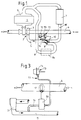
- the control valve 6 has a flap 10, which from a Actuator 11 is actuated.
- the actuator 11 in turn consists of a thermostat 12 and a pressure sensor 13, wherein the thermostat 12 detects the temperature of the intake air in the intake line 4.
- the pressure sensor 13 communicates via line 14 with the pressure line 5 and, after a predetermined pressure level has been exceeded, switches the flap 10 out of the position shown in such a way that the air initially led via the bypass line 8 or an air preheater 8a built into the bypass line 8 follows the charge air cooler 7 must pass when a predetermined pressure level is reached via a charge air line 15.
- the pressure sensor 13 is influenced by the temperature of the intake air from the thermostat 12 in such a way that the pressure level specified for actuating the flap 10 is set higher at a low temperature of the air in the intake line 4 than at a higher temperature of the air in the intake line 4
- the case is, that is, that the pressure sensor 13 responds only at a higher pressure level at a lower temperature of the intake air than is the case at a higher temperature of the intake air.
- the method according to the invention is based on the knowledge that the temperature difference between the air in the suction line 4 and the pressure line 5 can be described by their pressure difference in the form of a polytropic change in state.
- the particular advantage of the method according to the invention can be seen in the fact that the pressure sensor 13 of the actuator 11 responds much faster than a thermostat could do.
- the thermostat 12 only has the task of varying the response pressure of the pressure sensor 13 as a function of the ambient temperature.
- the inertia of the thermostat 12, which is still present, is insignificant, since the temperature of the air in the intake manifold 4 changes very slowly over time as a function of the ambient temperature.
- the flap 10 can be actuated by the pressure sensor 13 almost without delay.
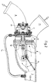
- FIG. 2 An embodiment of the actuator 11 is shown in Figure 2.
- the flap 10 connects the pressure line 5 either to the bypass line 8, or after switching from the position shown with a charge air line 15, which leads to the charge air cooler 7 ( Figure 1).
- the flap 10 is actuated primarily by the pressure sensor 13.
- a pressure chamber 16 of the pressure sensor 13 communicates with the pressure line 5 via the line 14.
- the reversal can be controlled by a membrane 17 and a linkage 18 the flap 10 from the position shown.
- the thermostat 12 reacting to the ambient temperature can be omitted.
- the temperature of the charge air is then only regulated via the pressure sensor 13 as a function of a polytropic change of state.
- a variation of the actuator 11 is shown schematically in Figure 3.
- the response pressure of the pressure sensor 13 is varied with the aid of a modulating valve 20 such that the pressure in the pressure chamber 16 of the pressure sensor 13 is raised when the temperature of the intake air in the intake line 4 drops, or vice versa.
- the modulating valve 20 is controlled by the thermostat 12 which is built into the intake line 4.
- the pressure in the pressure chamber 16 of the pressure sensor 13 can therefore be varied on the basis of the pressure in the pressure line 12 as a function of the temperature in the suction line 4 by means of the modulating valve 20.
- the thermostat 12 with the modulating valve can also be dispensed with here if the requirements for the constancy of the charge air temperature are reduced and emphasis is placed on simple design.
Abstract
Description
Die Erfindung bezieht sich auf ein Verfahren gemäß dem Gattungsbegriff des Patentanspruches 1.The invention relates to a method according to the preamble of
Aus DE-PS 32 14 205 ist eine Brennkraftmaschine mit Regelung der Ladelufttemperatur bekannt, bei der die Ladeluft nach einem Verdichter des Abgasturboladers durch ein Stellglied gesteuert entweder unter Zwischenschaltung eines Vorwärmers, oder eines Ladeluftkühlers dem Luftsammelrohr zugeführt wird. Der Weg der Ladeluft wird dabei durch ein temperaturabhängiges Stellglied gesteuert, welches am Eingang des Luftsammelrohrs angeordnet ist. Die temperaturabhängige Steuerung des Stellgliedes wird dabei durch eine Bimetallfeder bewerkstelligt. Wenn die vom Verdichter kommende Ladeluft zu kalt ist stellt die Bimetallfeder eine Klappe des Stellgliedes so, daß der Ausgang des Ladeluftkühlers versperrt wird, wodurch die Ladeluft über einen Vorwärmer geführt wird. Wenn eine ausreichende Temperatur für Ladeluft erreicht ist schaltet die Bimetallfeder die Klappe des Stellgliedes derart um, daß der Ausgang des Vorwärmers versperrt wird, so daß die Ladeluft über den Ladeluftkühler geführt wird. Da die Steuerung der Klappe durch die als Thermostat fungierende Bimetallfeder erfolgt reagiert die Umsteuerung mit hoher zeitlicher Verzögerung, da die Bimetallfeder wie auch andere handelsübliche Thermostate eine relativ hohe Wärmeträgheit aufweisen und daher erst mit zeitlicher Verzögerung ansprechen.From DE-PS 32 14 205 an internal combustion engine with control of the charge air temperature is known, in which the charge air is fed to the air manifold after a compressor of the exhaust gas turbocharger controlled by an actuator either with the interposition of a preheater or a charge air cooler. The path of the charge air is controlled by a temperature-dependent actuator, which is arranged at the entrance of the air manifold. The temperature-dependent control of the actuator is accomplished by a bimetal spring. If the charge air coming from the compressor is too cold, the bimetallic spring sets a flap of the actuator so that the outlet of the charge air cooler is blocked, whereby the charge air is guided through a preheater. When a sufficient temperature for charge air is reached, the bimetallic spring switches the valve of the actuator in such a way that the output of the preheater is blocked, so that the charge air is guided over the charge air cooler. Since the flap is controlled by the bimetal spring acting as a thermostat, the reversal reacts with a high time delay, since the bimetal spring, like other commercially available thermostats, has a relatively high thermal inertia and therefore only respond with a time delay.
Ausgehend von einer Vorrichtung gemäß dem Gattungsbegriff liegt der Erfindung die Aufgabe zugrunde ein Verfahren zu entwickeln, welches es gestattet, möglichst schnell die gewünschte Ladelufttemperatur zu erreichen, ohne daß dabei im höheren Lastbereich die Kühlung der Ladeluft verspätet einsetzt.On the basis of a device according to the generic term, the object of the invention is to develop a method which allows the desired charge air temperature to be reached as quickly as possible, without the charge air cooling being delayed in the higher load range.
Diese Aufgabe wird erfindungsgemäß durch die Merkmale des Patentanspruches 1 gelöst.This object is achieved by the features of
Dadurch, daß das Stellglied von einem Drucksensor angesteuert wird ergibt sich ein wesentlich schnelleres Ansprechen des Umsteuerungsmechanismus. Der Drucksensor folgt nahezu verzögerungsfrei dem Druckanstieg bzw. Druckabfall der Ladeluft, d. h. der physikalisch durch polytrope Verdichtung mit der Druckänderung einhergehenden Temperaturänderung.The fact that the actuator is controlled by a pressure sensor results in a much faster response of the reversing mechanism. The pressure sensor follows the pressure increase or pressure drop of the charge air almost without delay, i. H. the temperature change physically associated with the pressure change due to polytropic compression.
Eine Weiterbildung des Verfahrens nach Anpsruch 1 ist dem Anspruch 2 zu entnehmen.A further development of the method according to
Bei höheren Anforderungen an die Konstanz der Ladelufttemperatur kann der Drucksensor funktionell derart mit einem auf die Umgebungstemperatur reagierenden Thermostat gekoppelt werden, daß auch die zeitlich gesehen geringen Temperaturschwankungen der Umgebung berücksichtigt werden. Der den Drucksensor sekundär beeinflußende Thermostat reagiert lediglich auf die Temperatur in der Ansaugleitung, also eigentlich auf die herrschende Umgebungstemperatur, die sich zeitlich gesehen nur sehr langsam ändert, auf jeden Fall wesentlich langsamer als die Ladelufttemperatur hinter dem Verdichter im instationären Motorbetrieb.In the case of higher demands on the constancy of the charge air temperature, the pressure sensor can be functionally coupled to a thermostat that reacts to the ambient temperature in such a way that the temperature fluctuations in the environment, which are small over time, are also taken into account. The thermostat, which has a secondary influence on the pressure sensor, only reacts to the temperature in the intake line, i.e. actually to the prevailing ambient temperature, which changes very slowly over time, in any case much more slowly than the charge air temperature behind the compressor in unsteady engine operation.
Eine Vorrichtung zur Durchführung des Verfahrens nach den Patentansprüchen 1 und 2 kann dem Patentanspruch 3 entnommen werden.A device for performing the method according to
Der Drucksensor wird über eine Leitung mit der Druckleitung verbunden, wobei die Leitung zwischen Verdichter und Stellglied abzweigt und der Drucksensor löst durch den Druckanstieg nach dem Verdichter primär die Betätigung des Stellgliedes aus. Sekundär wirkt die Außentemperatur über die temperaturgeregelte Vorspannkraft der Feder auf den Drucksensor ein.The pressure sensor is connected to the pressure line via a line, the line between the compressor and the actuator branches off and the pressure sensor primarily triggers the actuation of the actuator due to the pressure increase after the compressor. Secondarily, the outside temperature acts on the pressure sensor via the temperature-controlled preload force of the spring.
Weitere vorteilhafte Ausführungen der Vorrichtung sind den Unteransprüchen 4 und 5 zu entnehmen.Further advantageous embodiments of the device can be found in
Ausführungsbeispiele für Vorrichtungen zur Durchführung des Verfahrens sind in Zeichnungen dargestellt. Es zeigt:
Figur 1- ein Schaltschema für die Regelung der Ladelufttemperatur
Figur 2- eine Vorrichtung zur Regelung der Ladelufttemperatur, wobei der Drucksensor sekundär von einem Thermostat beeinflußt wird
Figur 3- ein vom Thermostat geregeltes Modulierventil zur Beeinflussung des Drucksensors
Ein Schaltscheme zur Durchführung des erfindungsgemäßen Verfahrens ist aus
- Figure 1
- a circuit diagram for the regulation of the charge air temperature
- Figure 2
- a device for regulating the charge air temperature, the pressure sensor being influenced secondarily by a thermostat
- Figure 3
- a modulating valve controlled by the thermostat to influence the pressure sensor
A circuit diagram for carrying out the method according to the invention can be seen in FIG. 1. An
Das Regelventil 6 weist eine Klappe 10 auf, welche von einem Stellglied 11 betätigt wird. Das Stellglied 11 wiederum besteht aus einem Thermostat 12 und einem Drucksensor 13 wobei der Thermostat 12 die Temperatur der Ansaugluft in der Ansaugleitung 4 erfaßt. Der Drucksensor 13 kommuniziert über Leitung 14 mit der Druckleitung 5 und schaltet nach dem Überschreiten eines festgelegten Druckniveaus die Klappe 10 aus der gezeichneten Stellung heraus derart um, daß die zunächst über die Umgehungsleitung 8, oder einen in die Umgehungsleitung 8 eingebauten Luftvorwärmer 8a geführte Luft nach dem Erreichen eines vorgegebenen Druckniveaus über eine Ladeluftleitung 15 den Ladeluftkühler 7 passieren muß. Erfindungsgemäß wird der Drucksensor 13 über die Temperatur der Ansaugluft derart vom Thermostat 12 beeinflußt, daß das zur Betätigung der Klappe 10 vorgegebene Druckniveau bei niedriger Temperatur der Luft in der Ansaugleitung 4 höher angesetzt wird, als dies bei höherer Temperatur der Luft in der Ansaugleitung 4 der Fall ist, d. h., daß der Drucksensor 13 bei niedriger Temperatur der Ansaugluft erst bei einem höheren Druckniveau anspricht, als dies bei höherer Temperatur der Ansaugluft der Fall ist.The
Dem erfindungsgemäßen Verfahren liegt die Erkenntnis zugrunde, daß die Temperaturdifferenz zwischen der Luft in der Ansaugleitung 4 und der Druckleitung 5 durch deren Druckdifferenz in Form einer polytropen Zustandsänderung beschrieben werden kann. Der besondere Vorteil des erfindungsgemäßen Verfahrens ist darin zu sehen, daß der Drucksensor 13 des Stellgliedes 11 sehr viel schneller anspricht, als dies ein Thermostat leisten könnte. Der Thermostat 12 hat lediglich die Aufgabe den Ansprechdruck des Drucksensors 13 in Abhängigkeit von der Umgebungstemperatur zu variieren. Die nach wie vor vorhandene Trägheit des Thermostat 12 ist unbedeutend, da sich die Temperatur der Luft in der Ansaugletiung 4 in Abhängigkeit von der Umgebungstemperatur zeitlich gesehen nur sehr langsam ändert. Die Betätigugn der Klappe 10 kann durch den Drucksensor 13 nahezu verzögerungsfrei erfolgen.The method according to the invention is based on the knowledge that the temperature difference between the air in the suction line 4 and the
Ein Ausführungsbeispiel des Stellgliedes 11 ist in Figur 2 dargestellt. Die Klappe 10 verbindet die Druckleitung 5 entweder mit der Umgehungsleitung 8, oder nach dem Umschalten aus der gezeichneten Stellung mit einer Ladeluftleitung 15, welche zum Ladeluftkühler 7 führt (Figur 1). Die Betätigung der Klappe 10 erfolgt erfindungsgemäß primär durch den Drucksensor 13. Ein Druckraum 16 des Drucksensors 13 kommuniziert über die Leitung 14 mit der Druckleitung 5. Nach dem Erreichen eines vorgegebenen Druckes in der Druckleitung 5 kann durch eine Membran 17 und ein Gestänge 18 die Umsteuerung der Klappe 10 aus der gezeichneten Stellung heraus erfolgen. Eine zusätzliche von der Saugtemperatur abhängige Regulierung des Öffnungspunktes des Stellgliedes 11 wird durch die Änderung des Ansprechdruckes einer Druckfeder 19 im Drucksensor 13 bewerkstelligt, wobei die Druckfeder 19 von der Saugluft beaufschlagt wird und die Funktion des in Figur 1 dargestellten Thermostat 12 übernimmt, welcher von der Saugluft in der Ansaugleitung 4 beaufschlagt wird. Bei niedriger Temperatur der Ansaugluft besitzt die Druckfeder 19 eine höhere Vorspannkraft und die Membran 17 betätigt das Gestänge 18 zur Umsteuerung der Klappe 10 erst bei höherem Druck. Als Folge des höheren Druckgefälles erhöht sich das Temperaturgefälle und die Temperatur der Luft erreicht nach dem Verdichter 5 auch bei niedriger Umgebungstemperatur vor dem Umschalten der Klappe 10 wieder das gewünschte Temperaturniveau.An embodiment of the
Es ist leicht einzusehen, daß die Ansprechzeit des Drucksensors 13 sehr viel kleiner ist, als die Ansprechzeit eines Thermostat, der immer eine gewisse thermische Trägheit besitzt. Da sich aber die Außentemperatur nur sehr langsam verändert hat die Druckfeder 19 genügend Zeit sich auf veränderte Randbedingungen einzustellen.It is easy to see that the response time of the
Werden an die Konstanz der Ladeluft geringere Anforderungen gestellt, so kann der auf die Umgebungstemperatur reagierende Thermostat 12 entfallen. Die Temperatur der Ladeluft wird dann nur über den Drucksensor 13 als Funktion einer polytropen Zustandsänderung geregelt.If lower demands are made on the constancy of the charge air, the
Eine Variation des Stellgliedes 11 ist schematisch in Figur 3 dargestellt. Der Ansprechdruck des Drucksensors 13 wird mit Hilfe eines Modulierventils 20 derart variiert, daß der Druck im Druckraum 16 des Drucksensors 13 angehoben wird, wenn die Temperatur der Ansaugluft in der Ansaugleitung 4 absinkt, bzw. umgekehrt. Das Modulierventil 20 wird zu diesem Zweck vom Thermostat 12 angesteuert der in die Ansaugleitung 4 eingebaut ist. Der Druck im Druckraum 16 des Drucksensors 13 kann also ausgehend vom Druck in der Druckleitung 12 als Funktion der Temperatur in der Ansaugleitung 4 mittels des Modulierventils 20 variiert werden.A variation of the
Ebenso wie bei der Vorrichtung nach Figur 2 kann auch hier der Thermostat 12 mit dem Modulierventil entfallen wenn die Anforderungen an die Konstanz der Ladelufttemperatur gesenkt werden und Wert auf einfache Ausführung gelegt wird.As with the device according to FIG. 2, the
Eine weitere Möglichkeit der Betätigung des Stellgliedes 11 besteht darin, daß der Druck in der Druckleitung 5 und die Temperatur in der Ansaugleitung 4 mittels Sensoren erfaßt wird und die Werte dieser Sensoren einer Elektronik zur Auswertung zugeführt werden, wobei die Elektronik die Befehle zur Steuerung der Klappe 10 (Figur 1) erteilt. Der Vorteil einer derartigen Einrichtung besteht wiederum darin, daß der den Druckwert erfassende Sensor trägheitsfrei anspricht und eine nahezu verzögerungsfreie Steuerung der Klappe 10 ermöglicht.Another possibility of actuating the
Claims (5)
Applications Claiming Priority (2)
| Application Number | Priority Date | Filing Date | Title |
|---|---|---|---|
| DE4242010A DE4242010A1 (en) | 1992-12-12 | 1992-12-12 | Process for regulating the charge air temperature, and device for carrying it out |
| DE4242010 | 1992-12-12 |
Publications (1)
| Publication Number | Publication Date |
|---|---|
| EP0602348A1 true EP0602348A1 (en) | 1994-06-22 |
Family
ID=6475135
Family Applications (1)
| Application Number | Title | Priority Date | Filing Date |
|---|---|---|---|
| EP93116945A Withdrawn EP0602348A1 (en) | 1992-12-12 | 1993-10-20 | Method for controlling the temperature of the charging air and device to perform this method |
Country Status (3)
| Country | Link |
|---|---|
| EP (1) | EP0602348A1 (en) |
| JP (1) | JPH06212980A (en) |
| DE (1) | DE4242010A1 (en) |
Cited By (8)
| Publication number | Priority date | Publication date | Assignee | Title |
|---|---|---|---|---|
| EP0708231A1 (en) * | 1994-10-21 | 1996-04-24 | Valeo Thermique Moteur | Control device for the cooling of the charge air for heat engine |
| US5546975A (en) * | 1993-10-05 | 1996-08-20 | Renault Vehicules Industriels | Control device for a fluid passing through a bypass and system equipped with such a device to regulate the supercharging air of an internal combustion engine |
| WO1998025012A1 (en) * | 1996-12-02 | 1998-06-11 | Caterpillar Inc. | Air to air aftercooler heated bypass with load sensing switching valve |
| US5947064A (en) * | 1995-10-10 | 1999-09-07 | Man B&W Diesel A/S | Multi-engine plant with a common freshwater cooling system |
| FR2859504A1 (en) * | 2003-09-04 | 2005-03-11 | Renault Sa | CIRCUIT FOR SUPPLYING AN AIR INTAKE MANIFOLD OF A MOTOR VEHICLE THERMAL MOTOR |
| CN101432509B (en) * | 2006-04-26 | 2012-06-06 | 法雷奥电机控制系统公司 | Valve of air intake device for a heat engine |
| FR2970305A1 (en) * | 2011-01-11 | 2012-07-13 | Peugeot Citroen Automobiles Sa | Module for supplying air into internal combustion engine of motor vehicle, has routing arms provided with different dimensions and geometry such that routing arms are operated according to detected pumping tendency of compressor |
| CN109798179A (en) * | 2019-01-19 | 2019-05-24 | 潍柴重机股份有限公司 | A kind of pressurized air means of deflation and bleed method |
Families Citing this family (4)
| Publication number | Priority date | Publication date | Assignee | Title |
|---|---|---|---|---|
| DE4302339C2 (en) * | 1993-01-28 | 2001-06-07 | Bosch Gmbh Robert | Method and device for limiting the maximum permissible quantity of fuel |
| KR19980060474A (en) * | 1996-12-31 | 1998-10-07 | 박병재 | Supercharger of a car |
| EP1923552B1 (en) * | 2006-11-15 | 2013-07-24 | MANN+HUMMEL GmbH | Temperature control unit |
| FR2925610B1 (en) * | 2007-12-19 | 2014-03-28 | Valeo Sys Controle Moteur Sas | VALVE FOR THERMAL ENGINE AIR INTAKE SYSTEM |
Citations (10)
| Publication number | Priority date | Publication date | Assignee | Title |
|---|---|---|---|---|
| GB1153655A (en) * | 1966-07-23 | 1969-05-29 | Maschf Augsburg Nuernberg Ag | Improvements in or relating to Internal Combustion Engines |
| US3712282A (en) * | 1971-01-22 | 1973-01-23 | Teledyne Ind | Temperature control system for supercharged internal combustion engine |
| GB2001128A (en) * | 1977-07-12 | 1979-01-24 | Alsacienne Constr Meca | A supercharged diesel engine |
| GB2055963A (en) * | 1979-08-06 | 1981-03-11 | Alsacienne Constr Meca | Supercharging Internal Combustion Engines |
| FR2495689A1 (en) * | 1980-12-08 | 1982-06-11 | Hyperbar Develop Suralimentati | Coolant circuit for diesel engine - has heat exchanger in air intake for recuperator air and fuel circuit |
| EP0080984A2 (en) * | 1981-12-01 | 1983-06-08 | Ab Volvo | System for supplying combustion air to a super-charged combustion engine with charge air cooling |
| EP0080983A2 (en) * | 1981-12-01 | 1983-06-08 | Ab Volvo | System for supplying combustion air to a supercharged combustion engine with charge air cooling |
| JPS61112730A (en) * | 1984-11-05 | 1986-05-30 | Toyo Radiator Kk | Supply air cooling device for supercharger |
| JPS61190114A (en) * | 1985-02-18 | 1986-08-23 | Mazda Motor Corp | Surge preventer for turbo supercharger associated with inter-cooler |
| JPS63195324A (en) * | 1987-02-07 | 1988-08-12 | Mazda Motor Corp | Intake air cooling device for engine with supercharger |
Family Cites Families (4)
| Publication number | Priority date | Publication date | Assignee | Title |
|---|---|---|---|---|
| DE3214205A1 (en) * | 1982-04-17 | 1983-10-20 | Klöckner-Humboldt-Deutz AG, 5000 Köln | Internal combustion engine with at least one exhaust gas turbocharger |
| US4483150A (en) * | 1983-02-28 | 1984-11-20 | Societe Pour Le Developpement De La Suralimentation Hyperbar | Supercharged internal combustion engines provided with a cooling system |
| DE3627686A1 (en) * | 1986-08-14 | 1987-11-12 | Daimler Benz Ag | Internal combustion engine with an exhaust turbocharger |
| SU1726810A1 (en) * | 1990-05-29 | 1992-04-15 | Челябинское Высшее Военное Автомобильное Инженерное Училище Им.Главного Маршала Бронетанковых Войск П.А.Ротмистрова | Internal combustion engine supercharging air temperature control device |
-
1992
- 1992-12-12 DE DE4242010A patent/DE4242010A1/en not_active Withdrawn
-
1993
- 1993-10-20 EP EP93116945A patent/EP0602348A1/en not_active Withdrawn
- 1993-12-13 JP JP5311936A patent/JPH06212980A/en active Pending
Patent Citations (10)
| Publication number | Priority date | Publication date | Assignee | Title |
|---|---|---|---|---|
| GB1153655A (en) * | 1966-07-23 | 1969-05-29 | Maschf Augsburg Nuernberg Ag | Improvements in or relating to Internal Combustion Engines |
| US3712282A (en) * | 1971-01-22 | 1973-01-23 | Teledyne Ind | Temperature control system for supercharged internal combustion engine |
| GB2001128A (en) * | 1977-07-12 | 1979-01-24 | Alsacienne Constr Meca | A supercharged diesel engine |
| GB2055963A (en) * | 1979-08-06 | 1981-03-11 | Alsacienne Constr Meca | Supercharging Internal Combustion Engines |
| FR2495689A1 (en) * | 1980-12-08 | 1982-06-11 | Hyperbar Develop Suralimentati | Coolant circuit for diesel engine - has heat exchanger in air intake for recuperator air and fuel circuit |
| EP0080984A2 (en) * | 1981-12-01 | 1983-06-08 | Ab Volvo | System for supplying combustion air to a super-charged combustion engine with charge air cooling |
| EP0080983A2 (en) * | 1981-12-01 | 1983-06-08 | Ab Volvo | System for supplying combustion air to a supercharged combustion engine with charge air cooling |
| JPS61112730A (en) * | 1984-11-05 | 1986-05-30 | Toyo Radiator Kk | Supply air cooling device for supercharger |
| JPS61190114A (en) * | 1985-02-18 | 1986-08-23 | Mazda Motor Corp | Surge preventer for turbo supercharger associated with inter-cooler |
| JPS63195324A (en) * | 1987-02-07 | 1988-08-12 | Mazda Motor Corp | Intake air cooling device for engine with supercharger |
Non-Patent Citations (3)
| Title |
|---|
| PATENT ABSTRACTS OF JAPAN vol. 10, no. 299 (M - 524)<2355> 11 October 1986 (1986-10-11) * |
| PATENT ABSTRACTS OF JAPAN vol. 11, no. 14 (M - 553)<2461> 14 January 1987 (1987-01-14) * |
| PATENT ABSTRACTS OF JAPAN vol. 12, no. 475 (M - 774)<3322> 13 December 1988 (1988-12-13) * |
Cited By (11)
| Publication number | Priority date | Publication date | Assignee | Title |
|---|---|---|---|---|
| US5546975A (en) * | 1993-10-05 | 1996-08-20 | Renault Vehicules Industriels | Control device for a fluid passing through a bypass and system equipped with such a device to regulate the supercharging air of an internal combustion engine |
| EP0708231A1 (en) * | 1994-10-21 | 1996-04-24 | Valeo Thermique Moteur | Control device for the cooling of the charge air for heat engine |
| FR2726039A1 (en) * | 1994-10-21 | 1996-04-26 | Valeo Thermique Moteur Sa | DEVICE FOR CONTROLLING THE COOLING OF THE HEATER AIR OF A THERMAL ENGINE |
| US5649516A (en) * | 1994-10-21 | 1997-07-22 | Valeo Thermique Moteur | Device for controlling the temperature of supercharging air for a heat engine |
| US5947064A (en) * | 1995-10-10 | 1999-09-07 | Man B&W Diesel A/S | Multi-engine plant with a common freshwater cooling system |
| WO1998025012A1 (en) * | 1996-12-02 | 1998-06-11 | Caterpillar Inc. | Air to air aftercooler heated bypass with load sensing switching valve |
| FR2859504A1 (en) * | 2003-09-04 | 2005-03-11 | Renault Sa | CIRCUIT FOR SUPPLYING AN AIR INTAKE MANIFOLD OF A MOTOR VEHICLE THERMAL MOTOR |
| EP1512853A3 (en) * | 2003-09-04 | 2010-05-19 | Renault s.a.s. | Supply circuit for air intake manifold collector of a vehicle combustion engine |
| CN101432509B (en) * | 2006-04-26 | 2012-06-06 | 法雷奥电机控制系统公司 | Valve of air intake device for a heat engine |
| FR2970305A1 (en) * | 2011-01-11 | 2012-07-13 | Peugeot Citroen Automobiles Sa | Module for supplying air into internal combustion engine of motor vehicle, has routing arms provided with different dimensions and geometry such that routing arms are operated according to detected pumping tendency of compressor |
| CN109798179A (en) * | 2019-01-19 | 2019-05-24 | 潍柴重机股份有限公司 | A kind of pressurized air means of deflation and bleed method |
Also Published As
| Publication number | Publication date |
|---|---|
| DE4242010A1 (en) | 1994-06-16 |
| JPH06212980A (en) | 1994-08-02 |
Similar Documents
| Publication | Publication Date | Title |
|---|---|---|
| DE3039435C2 (en) | Device for regulating the idling speed of internal combustion engines | |
| DE3205111C2 (en) | ||
| DE19502150C1 (en) | System for regulating supercharging of IC engine | |
| DE3020131C2 (en) | ||
| EP0602348A1 (en) | Method for controlling the temperature of the charging air and device to perform this method | |
| DE3636642A1 (en) | CHARGING SYSTEM FOR MOTOR VEHICLE ENGINES | |
| DE10256966A1 (en) | Bypass valve system on a turbocharged engine | |
| DE3000781C2 (en) | Device for controlling the actuation pressure for the actuator of a bypass valve in a bypass line of the turbine of an exhaust gas turbocharger | |
| DE2003924C3 (en) | Control device for a fuel injection device | |
| DE102014210207A1 (en) | Control device and control method for internal combustion engine | |
| DE3138058C2 (en) | ||
| DE3238189A1 (en) | IDLE CONTROL SYSTEM FOR AN INTERNAL COMBUSTION ENGINE | |
| JPH0472985B2 (en) | ||
| EP0035691B1 (en) | Charging pressure control device for internal-combustion engines | |
| EP0456778A1 (en) | System for regulating an operative parameter of an internal combustion engine of a motor vehicle. | |
| EP0434788B1 (en) | Control system for an internal-combustion engine | |
| US2796733A (en) | Turbine engine fuel control using a final electrical signal for proportionally moving a single throttle valve | |
| GB1237680A (en) | Flow metering apparatus, particularly for combustion engine fuel control | |
| EP1830049B1 (en) | Method and control unit for adjusting in a turbocharger a turbine flow cross section | |
| EP0728922B1 (en) | Controller with adapted integral part for the air mass flow of a turbocharged internal combustion engine | |
| EP0399016B1 (en) | Process and device for adapting the characteristic curve of an idling regulator | |
| DE2822207C3 (en) | Device for regulating the charge air pressure | |
| DE3124676C2 (en) | ||
| DE1290373B (en) | Fuel control system for gas turbine engines | |
| EP1036919A2 (en) | Internal combustion engine with an exhaust gas regulation device |
Legal Events
| Date | Code | Title | Description |
|---|---|---|---|
| PUAI | Public reference made under article 153(3) epc to a published international application that has entered the european phase |
Free format text: ORIGINAL CODE: 0009012 |
|
| AK | Designated contracting states |
Kind code of ref document: A1 Designated state(s): AT DE FR IT SE |
|
| STAA | Information on the status of an ep patent application or granted ep patent |
Free format text: STATUS: THE APPLICATION IS DEEMED TO BE WITHDRAWN |
|
| 18D | Application deemed to be withdrawn |
Effective date: 19941223 |