EP0601896B1 - Header box and expansion chamber for a heat-exchanger, especially for a motor vehicle - Google Patents
Header box and expansion chamber for a heat-exchanger, especially for a motor vehicle Download PDFInfo
- Publication number
- EP0601896B1 EP0601896B1 EP19930401035 EP93401035A EP0601896B1 EP 0601896 B1 EP0601896 B1 EP 0601896B1 EP 19930401035 EP19930401035 EP 19930401035 EP 93401035 A EP93401035 A EP 93401035A EP 0601896 B1 EP0601896 B1 EP 0601896B1
- Authority
- EP
- European Patent Office
- Prior art keywords
- reservoir
- partition member
- removable partition
- unit according
- partition
- Prior art date
- Legal status (The legal status is an assumption and is not a legal conclusion. Google has not performed a legal analysis and makes no representation as to the accuracy of the status listed.)
- Expired - Lifetime
Links
Images
Classifications
-
- F—MECHANICAL ENGINEERING; LIGHTING; HEATING; WEAPONS; BLASTING
- F28—HEAT EXCHANGE IN GENERAL
- F28F—DETAILS OF HEAT-EXCHANGE AND HEAT-TRANSFER APPARATUS, OF GENERAL APPLICATION
- F28F9/00—Casings; Header boxes; Auxiliary supports for elements; Auxiliary members within casings
- F28F9/02—Header boxes; End plates
- F28F9/0231—Header boxes having an expansion chamber
-
- F—MECHANICAL ENGINEERING; LIGHTING; HEATING; WEAPONS; BLASTING
- F28—HEAT EXCHANGE IN GENERAL
- F28F—DETAILS OF HEAT-EXCHANGE AND HEAT-TRANSFER APPARATUS, OF GENERAL APPLICATION
- F28F2275/00—Fastening; Joining
- F28F2275/08—Fastening; Joining by clamping or clipping
- F28F2275/085—Fastening; Joining by clamping or clipping with snap connection
Definitions
- the invention relates to a water box and expansion tank device for a heat exchanger, in particular for a radiator for cooling a motor vehicle engine.
- the tank forms an integrated assembly bringing together the water box and the expansion tank and it is connected, via the collector plate, to one end of a bundle of tubes, including another end. is connected to another water box.
- the heat exchanger thus formed is intended to be traversed by a liquid, generally water added with an antifreeze, which circulates in a closed circuit to serve for example for the cooling of an internal combustion engine.
- the liquid is itself cooled by heat exchange with an air flow which scans the tubes of the bundle.
- the coolant enters the water box compartment of the tank and then reaches the other water box.
- the expansion vessel compartment which is placed above the water box compartment, is intended to absorb variations in the volume of the liquid as a function of temperature and to collect any water and gas bubbles that may be present in the circuit, so as to avoid the formation of hot spots on the cylinder head of the engine. We then provide a degassing making the two compartments of the tank communicate.
- the object of the invention is in particular to overcome the drawbacks mentioned above.
- the invention provides a device for a water box and expansion tank of the type defined in the introduction, which comprises a main spacer formed projecting from the partition and terminated by a latching head suitable for being introduced. in force in a suitably shaped sleeve which depends on the bottom wall and in which the main spacer is formed in a middle region of the partition.
- the partition is connected to the bottom wall and kept at a distance therefrom, which allows it to withstand pressure differences between the two tank compartments.
- the device further comprises at least one secondary spacer attached to the bottom wall of the tank and terminated by a latching head capable of being forced into an opening of suitable shape which is provided in the partition.
- the device comprises two secondary spacers respectively attached to two end regions opposite the bottom wall.
- the partition is kept at a distance from the bottom wall, not only in the middle, but also in two end regions.
- two opposite end regions of the partition each comprise at least one lug connecting to the partition and suitable for bearing against the collector plate, after assembly of the latter with the reservoir.
- the partition is also kept at a given distance from the collector plate, which is located opposite the bottom wall.
- the device comprises two support legs in each of the end regions of the partition.
- the reservoir internally comprises, in each of two opposite regions thereof, at least one immobilizing tab suitable for engaging in a housing of suitable shape, formed in an edge of end of the partition, which allows it to be immobilized.
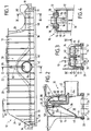
- the device shown in Figures 1 to 4 comprises a reservoir 10 made in one piece by molding a plastic material.
- This reservoir comprises two large opposite faces 12 and 14 and two small opposite faces 16 and 18, these four faces being connected by a bottom wall 20.
- the latter itself comprises a main part 22 in the shape of a dome with a straight section semi-circular (Figure 2) which connects to the sides 16 and 18 respectively by two inclined sides 24 and 26 also forming part of the bottom wall.
- the faces 12, 14, 16 and 18 lead to a peripheral rim 28 of generally rectangular outline delimiting an open face 30.
- the peripheral rim 28 allows the reservoir 10 to be assembled on a collecting plate 32 (shown in phantom in Figures 2 and 3) and this in a manner known per se.
- This collector plate comprises a multiplicity of holes for the sealed mounting of a multiplicity of tubes 34 (also shown in phantom line) forming a beam.
- the device further comprises an internal partition 36 which extends over the entire length and entire width of the tank 10 to divide it into two separate compartments: a lower compartment 38 forming a water box disposed on the side of the collecting plate 32 and a upper compartment 40 forming an expansion vessel and disposed on the side of the bottom wall 20.
- the reservoir 10 comprises a tube 42 depending on the face 12 and located, in the example, substantially in the middle, this tube opening into the compartment 38 to allow the admission of a coolant.
- the reservoir 10 further comprises a filling base 44 attached to the bottom wall 20 and communicating with the compartment 40.
- the partition 36 has a peripheral edge 46 tightly connected to a peripheral bearing edge 48 of the tank.
- the bearing edge 48 is constituted by a shoulder molded and extending over the entire length of the faces 12 and 14 and over the entire width of the faces 16 and 18.
- the peripheral edge 46 has a curved part 50 adapted to cooperate with a curved part homologous 52 of the bearing edge 48 in the region of the tubing 42, so that the latter opens into the compartment 38.
- a main spacer 54 (FIG. 2) is formed projecting over a central region of the partition 36.
- the spacer 54 extends in a direction substantially perpendicular to that of the open face 30 and it ends by a latching head 56 suitable for being forced into a sleeve 58 of suitable shape which depends on the bottom wall 20.
- the sleeve 58 is formed projecting from the bottom wall 20 and extends in a direction generally perpendicular to the open face 30.
- the head 56 is snapped into the sleeve 58 to ensure that the partition 36 is held in its middle part.
- the device further comprises two secondary spacers 60 and 62 (Figure 1) attached to the bottom wall 20 of the reservoir 10.
- the spacer 60 is attached to the sidewall 26 and ends with a clean latching head 64 (Figure 3) to be introduced by force into an opening 66 of suitable shape (FIG. 4) which is formed in the partition 36 in an end region 68 thereof, which is located close to the face 18 of the reservoir 10.
- the other secondary spacer 62 is attached to an opposite end region of the bottom wall, that is to say to the side 24. It also ends with a similar snap-on head (not visible in the drawings) to the head 64 described above.
- This latching head is adapted to cooperate with an opening similar to the opening 66 and formed in an opposite end region 70 of the partition 36, which is located close to the face 16 of the reservoir 10 (FIG. 1).
- the end region 68 of the partition 36 ends in two spaced apart legs 72 (FIGS. 1, 3 and 4), capable of bearing perpendicularly against the collecting plate 32 after assembly of the latter with the reservoir 10.
- the two tabs 72 are housed in the two regions which respectively connect the face 18 with the faces 12 and 14 of the tank.
- the other end region 70 of the partition comprises two similar tabs 74 capable of bearing against the collecting plate 32 and coming to be housed in the two regions which respectively connect the face 16 with the faces 12 and 14 of the tank.
- the tabs 72 and 74 contribute to maintaining the partition in position, by allowing the edge 46 to rest against the rim 48 in the end regions of the tank.
- the reservoir 10 has internally two immobilization tabs 76 located in the connection zone of the sidewall 26 and of the face 18. These two tabs 76 are elastic and extend in directions generally perpendicular to the open face 30 of the reservoir.
- the two tabs 76 in the form of a tongue, are intended to be fitted into two housings 78 of suitable shape (FIG. 4) provided in the end region 68 of the partition 36.
- the two housings 78 are located in the immediate vicinity legs 72 mentioned above.
- the reservoir 10 further comprises two other similar tabs (not shown) formed in the connection zone of the sidewall 24 and of the face 16 and suitable for cooperating with suitable housings (not visible in the drawings) which the end region has 70 of the partition 36.
- the aforementioned legs immobilize the partition and prevent it from moving in directions generally parallel to the collector plate 32.
- the partition 36 also includes a degassing conduit 82 molded therewith.
- This degassing duct is suitable for establishing communication between the intake manifold 42 opening into the tank 38 and the expansion tank compartment 40.
- the duct 82 has a bent shape and has a first branch 84 opening into the upper part of the tubing 42 and a branch 46 extending perpendicularly to the branch 84 and opening at the top of the compartment 40.
- the degassing duct 82 is intended to trap the air or gas bubbles about to penetrate into the compartment 38 in order to evacuate them towards the compartment 40.
- partition 36 is effectively maintained inside the tank 10 and can thus resist the significant pressure differences which may appear between the compartments 38 and 40.
- spacers 54, 60 and 62 already allow the partition to be held inside the tank before mounting it on the manifold, that is to say before mounting the heat exchanger.
- the device of the invention is particularly suitable for the manufacture of heat exchangers for cooling internal combustion engines, in particular diesel engines.
Description
L'invention concerne un dispositif de boîte à eau et de vase d'expansion pour un échangeur de chaleur, en particulier pour un radiateur de refroidissement d'un moteur de véhicule automobile.The invention relates to a water box and expansion tank device for a heat exchanger, in particular for a radiator for cooling a motor vehicle engine.
Elle concerne plus particulièrement un dispositif du type revendiqué dans le préambule de la revendication 1.It relates more particularly to a device of the type claimed in the preamble of claim 1.
Dans un tel dispositif, le réservoir forme un ensemble intégré rassemblant la boîte à eau et le vase d'expansion et il se raccorde, par l'intermédiaire de la plaque collectrice, à une extrémité d'un faisceau de tubes, dont une autre extrémité est raccordée à une autre boîte à eau.In such a device, the tank forms an integrated assembly bringing together the water box and the expansion tank and it is connected, via the collector plate, to one end of a bundle of tubes, including another end. is connected to another water box.
L'échangeur de chaleur ainsi constitué est destiné à être parcouru par un liquide, généralement de l'eau additionnée d'un antigel, qui circule en circuit fermé pour servir par exemple au refroidissement d'un moteur à combustion interne. Le liquide est lui-même refroidi par échange thermique avec un flux d'air qui balaie les tubes du faisceau.The heat exchanger thus formed is intended to be traversed by a liquid, generally water added with an antifreeze, which circulates in a closed circuit to serve for example for the cooling of an internal combustion engine. The liquid is itself cooled by heat exchange with an air flow which scans the tubes of the bundle.
Le liquide de refroidissement pénètre dans le compartiment boîte à eau du réservoir pour gagner ensuite l'autre boite à eau. Le compartiment formant vase d'expansion, qui est placé au-dessus du compartiment formant boîte à eau, est destiné à absorber les variations de volume du liquide en fonction de la température et à rassembler les bulles d'eau et de gaz éventuellement présentes dans le circuit, de manière à éviter la formation de points chauds sur la culasse du moteur. On prévoit alors un conduit de dégazage faisant communiquer les deux compartiments du réservoir.The coolant enters the water box compartment of the tank and then reaches the other water box. The expansion vessel compartment, which is placed above the water box compartment, is intended to absorb variations in the volume of the liquid as a function of temperature and to collect any water and gas bubbles that may be present in the circuit, so as to avoid the formation of hot spots on the cylinder head of the engine. We then provide a degassing making the two compartments of the tank communicate.
On connaît déjà, d'après FR-A-2 395 397, un dispositif de boîte à eau et de vase d'expansion du type défini ci-dessus, dans lequel la cloison est raccordée au réservoir par l'intermédiaire d'un joint d'étanchéité.Already known, from FR-A-2 395 397, a water box and expansion tank device of the type defined above, in which the partition is connected to the tank by means of a seal sealing.
On connaît également par le document DE-A-3 006 093, qui est considéré comme l'état de la technique le plus proche, un dispositif de boîte à eau et de vase d'expansion dans lequel il est prévu au moins une entretoise munie de moyens d'encliquetage pour relier la cloison amovible à une paroi du réservoir.Also known from document DE-A-3 006 093, which is considered to be the closest state of the art, is a water box and expansion tank device in which at least one spacer is provided. latching means for connecting the removable partition to a wall of the tank.
Ces dispositifs connus ont pour inconvénient que, sous l'effet de différences de pression importantes entre les deux compartiments du réservoir, la cloison s'écarte de sa position, si bien que l'étanchéité du raccordement n'est plus assurée.These known devices have the drawback that, under the effect of significant pressure differences between the two compartments of the tank, the partition deviates from its position, so that the connection is no longer sealed.
En outre, il peut arriver que, lors de d'assemblage sur des chaînes de montage automatisées, la cloison se sépare du réservoir.In addition, it may happen that, during assembly on automated assembly lines, the partition separates from the tank.
De plus, sous l'effet de la pression, il peut se produire que les moyens d'encliquetage ne coopèrent plus entre eux et la cloison se détache des parois du réservoir.In addition, under the effect of pressure, it may occur that the latching means no longer cooperate with each other and the partition is detached from the walls of the tank.
L'invention a notamment pour but de surmonter les inconvénients mentionnés ci-dessus.The object of the invention is in particular to overcome the drawbacks mentioned above.
C'est en particulier un but de l'invention de procurer un tel dispositif dans lequel la cloison est maintenue efficacement à l'intérieur du réservoir, de manière à pouvoir résister à des différences de pression importantes entre les deux compartiments.It is in particular an object of the invention to provide such a device in which the partition is effectively maintained inside the tank, so as to be able to withstand significant pressure differences between the two compartments.
C'est également un but de l'invention de procurer un tel dispositif dans lequel la cloison reste solidaire du réservoir pendant les opérations sur une chaîne automatisée.It is also an object of the invention to provide such a device in which the partition remains secured to the tank during operations on an automated chain.
L'invention propose à cet effet un dispositif de boîte à eau et de vase d'expansion du type défini en introduction, lequel comprend une entretoise principale formée en saillie à partir de la cloison et terminée par une tête d'encliquetage propre à être introduite en force dans un manchon de forme adaptée qui dépend de la paroi de fond et dans lequel l'entretoise principale est formée dans une région médiane de la cloison.To this end, the invention provides a device for a water box and expansion tank of the type defined in the introduction, which comprises a main spacer formed projecting from the partition and terminated by a latching head suitable for being introduced. in force in a suitably shaped sleeve which depends on the bottom wall and in which the main spacer is formed in a middle region of the partition.
Ainsi, la cloison est reliée à la paroi de fond et maintenue à distance de celle-ci, ce qui lui permet de résister aux différences de pression régnant entre les deux compartiments du réservoir.Thus, the partition is connected to the bottom wall and kept at a distance therefrom, which allows it to withstand pressure differences between the two tank compartments.
Par ailleurs, du fait des moyens d'encliquetage de la ou chaque entretoise, le montage de la cloison à l'intérieur du réservoir est grandement facilité.Furthermore, due to the latching means of the or each spacer, the mounting of the partition inside the tank is greatly facilitated.
Selon une autre caractéristique de l'invention, le dispositif comprend en outre au moins une entretoise secondaire rattachée à la paroi de fond du réservoir et terminée par une tête d'encliquetage propre à être introduite en force dans une ouverture de forme adaptée qui est ménagée dans la cloison.According to another characteristic of the invention, the device further comprises at least one secondary spacer attached to the bottom wall of the tank and terminated by a latching head capable of being forced into an opening of suitable shape which is provided in the partition.
De préférence, le dispositif comprend deux entretoises secondaires rattachées respectivement a deux régions d'extrémité opposées à la paroi de fond.Preferably, the device comprises two secondary spacers respectively attached to two end regions opposite the bottom wall.
Ainsi, la cloison se trouve maintenue à distance de la paroi de fond, non seulement en son milieu, amis aussi en deux régions d'extrémité.Thus, the partition is kept at a distance from the bottom wall, not only in the middle, but also in two end regions.
Selon une autre caractéristique avantageuse de l'invention, deux régions d'extrémité opposées de la cloison comprennent chacune au moins une patte se rattachant à la cloison et propre à prendre appui contre la plaque collectrice, après assemblage de cette dernière avec le réservoir.According to another advantageous characteristic of the invention, two opposite end regions of the partition each comprise at least one lug connecting to the partition and suitable for bearing against the collector plate, after assembly of the latter with the reservoir.
Ainsi, la cloison se trouve également maintenue à une distance donnée par rapport à la plaque collectrice, laquelle est située à l'opposé de la paroi de fond.Thus, the partition is also kept at a given distance from the collector plate, which is located opposite the bottom wall.
Dans une forme de réalisation préférée de l'invention, le dispositif comprend deux pattes d'appui dans chacune des régions d'extrémité de la cloison.In a preferred embodiment of the invention, the device comprises two support legs in each of the end regions of the partition.
Selon une autre caractéristique de l'invention, le réservoir comporte intérieurement, dans chacune de deux régions opposées de celui-ci, au moins une patte d'immobilisation propre à s'engager dans un logement de forme adaptée, ménagé dans un bord d'extrémité de la cloison, ce qui permet de l'immobiliser.According to another characteristic of the invention, the reservoir internally comprises, in each of two opposite regions thereof, at least one immobilizing tab suitable for engaging in a housing of suitable shape, formed in an edge of end of the partition, which allows it to be immobilized.
On empêche ainsi la cloison de se déplacer dans des directions généralement parallèles à la plaque collectrice.This prevents the partition from moving in directions generally parallel to the header plate.
Dans la description qui suit, faite seulement à titre d'exemple, on se réfère au dessin annexé, sur lequel :
- la figure 1 est une vue en élévation d'un dispositif de boîte à eau et de vase d'expansion selon l'invention ;
- la figure 2 est une vue en coupe, à échelle agrandie, selon la ligne II-II de la figure 1 ;
- la figure 3 est une vue en coupe, à échelle agrandie, selon la ligne III-III de la figure 2 ; et
- la figure 4 est une vue en coupe partielle selon la ligne IV-IV de la figure 3.
- Figure 1 is an elevational view of a water box and expansion tank device according to the invention;
- Figure 2 is a sectional view, on an enlarged scale, along the line II-II of Figure 1;
- Figure 3 is a sectional view, on an enlarged scale, along the line III-III of Figure 2; and
- FIG. 4 is a partial sectional view along the line IV-IV of FIG. 3.
Le dispositif représenté aux figures 1 à 4 comprend un réservoir 10 réalisé d'une seule pièce par moulage d'une matière plastique. Ce réservoir comprend deux grandes faces opposées 12 et 14 et deux petites faces opposées 16 et 18, ces quatre faces étant reliées par une paroi de fond 20. Cette dernière comprend elle-même une partie principale 22 en forme de dôme à section droite semi-circulaire (figure 2) qui se raccorde aux côtés 16 et 18 respectivement par deux flancs inclinés 24 et 26 faisant également partie de la paroi de fond.The device shown in Figures 1 to 4 comprises a
Les faces 12, 14, 16 et 18 aboutissent à un rebord périphérique 28 de contour général rectangulaire délimitant une face ouverte 30. Le rebord périphérique 28 permet l'assemblage du réservoir 10 sur une plaque collectrice 32 (représentée en trait fantôme sur les figures 2 et 3) et cela d'une manière connue en soi. Cette plaque collectrice comporte une multiplicité de trous pour le montage étanche d'une multiplicité de tubes 34 (également représentés en trait fantôme) formant faisceau.The
Le dispositif comprend en outre une cloison interne 36 qui s'étend sur toute la longueur et toute la largeur du réservoir 10 pour le diviser en deux compartiments distincts : un compartiment inférieur 38 formant boîte à eau disposé du côté de la plaque collectrice 32 et un compartiment supérieur 40 formant vase d'expansion et disposé du côté de la paroi de fond 20.The device further comprises an
Le réservoir 10 comprend une tubulure 42 dépendant de la face 12 et située, dans l'exemple, sensiblement en son milieu, cette tubulure débouchant dans le compartiment 38 pour permettre l'admission d'un liquide de refroidissement. Le réservoir 10 comprend en outre une embase de remplissage 44 rattachée à la paroi de fond 20 et communiquant avec le compartiment 40.The
La cloison 36 présente un bord périphérique 46 relié de façon étanche à un bord d'appui périphérique 48 du réservoir. Le bord d'appui 48 est constitué par un épaulement venu de moulage et s'étendant sur toute la longueur des faces 12 et 14 et sur toute la largeur des faces 16 et 18. Ainsi, lorsque la cloison 36 est introduite à l'intérieur du réservoir 10, à partir de sa face ouverte 30, une liaison étanche est obtenue entre le bord périphérique 46 et le bord d'appui 48 avec interposition, le cas échéant, d'un joint d'étanchéité. Il est à noter que le bord périphérique 46 présente une partie incurvée 50 propre à coopérer avec une partie incurvée homologue 52 du bord d'appui 48 dans la région de la tubulure 42, de manière que cette dernière débouche dans le compartiment 38.The
Conformément à l'invention, une entretoise principale 54 (figure 2) est formée en saillie sur une région médiane de la cloison 36. L'entretoise 54 s'étend dans une direction sensiblement perpendiculaire à celle de la face ouverte 30 et elle se termine par une tête d'encliquetage 56 propre à être introduite en force dans un manchon 58 de forme adaptée qui dépend de la paroi de fond 20. Le manchon 58 est formé en saillie à partir de la paroi de fond 20 et s'étend dans une direction généralement perpendiculaire à la face ouverte 30.According to the invention, a main spacer 54 (FIG. 2) is formed projecting over a central region of the
Ainsi, lors du montage de la boîte 36, la tête 56 vient s'encliqueter dans le manchon 58 pour assurer un maintien de la cloison 36 dans sa partie médiane.Thus, during assembly of the
Le dispositif comprend en outre deux entretoises secondaires 60 et 62 (figure 1) rattachées à la paroi de fond 20 du réservoir 10. L'entretoise 60 est rattachée au flanc 26 et se termine par une tête d'encliquetage 64 (figure 3) propre à être introduite en force dans une ouverture 66 de forme adaptée (figure 4) qui est ménagée dans la cloison 36 dans une région d'extrémité 68 de celle-ci, qui est située proche de la face 18 du réservoir 10.The device further comprises two
L'autre entretoise secondaire 62 est rattachée à une région d'extrémité opposée de la paroi de fond, c'est-à-dire au flanc 24. Elle se termine également par une tête d'encliquetage (non visible sur les dessins) analogue à la tête 64 décrite précédemment. Cette tête d'encliquetage est propre à coopérer avec une ouverture analogue à l'ouverture 66 et ménagée dans une région d'extrémité opposée 70 de la cloison 36, qui est située proche de la face 16 du réservoir 10 (figure 1).The other
La région d'extrémité 68 de la cloison 36 se termine par deux pattes espacées 72 (figures 1, 3 et 4), propres à prendre appui perpendiculairement contre la plaque collectrice 32 après assemblage de cette dernière avec le réservoir 10.The
Comme on le voit mieux sur la figure 4, les deux pattes 72 viennent se loger dans les deux régions qui raccordent respectivement la face 18 avec les faces 12 et 14 du réservoir.As best seen in Figure 4, the two
L'autre région d'extrémité 70 de la cloison comporte deux pattes analogues 74 propres à prendre appui contre la plaque collectrice 32 et venant se loger dans les deux régions qui raccordent respectivement la face 16 avec les faces 12 et 14 du réservoir. Les pattes 72 et 74 contribuent au maintien en position de la cloison, en permettant un appui du bord 46 contre le rebord 48 dans les régions d'extrémité du réservoir.The
Le réservoir 10 comporte intérieurement deux pattes d'immobilisation 76 situées dans la zone de raccordement du flanc 26 et de la face 18. Ces deux pattes 76 sont élastiques et s'étendent dans des directions généralement perpendiculaires à la face ouverte 30 du réservoir. Les deux pattes 76, en forme de languette, sont destinées à venir s'encastrer dans deux logements 78 de forme adaptée (figure 4) prévus dans la région d'extrémité 68 de la cloison 36. Les deux logements 78 sont situés à proximité immédiate des pattes 72 mentionnées précédemment.The
Le réservoir 10 comprend en outre deux autres pattes analogues (non représentées) formées dans la zone de raccordement du flanc 24 et de la face 16 et propres à coopérer avec des logements appropriés (non visibles sur les dessins) que comporte la région d'extrémité 70 de la cloison 36. Les pattes précitées immobi lisent la cloison et l'empêchent de se déplacer dans des directions généralement parallèles à la plaque collectrice 32.The
La cloison 36 comporte par ailleurs un conduit de dégazage 82 venu de moulage avec elle. Ce conduit de dégazage est propre à établir une communication entre la tubulure d'admission 42 débouchant dans le réservoir 38 et le compartiment vase d'expansion 40. Le conduit 82 a une forme coudée et comporte une première branche 84 débouchant dans la partie supérieure de la tubulure 42 et une branche 46 s'étendant perpendiculairement à la branche 84 et débouchant au sommet du compartiment 40. Le conduit de dégazage 82 est destiné à pièger les bulles d'air ou de gaz sur le point de pénétrer dans le compartiment 38 pour les évacuer vers le compartiment 40.The
On comprendra que la cloison 36 se trouve maintenue efficacement à l'intérieur du réservoir 10 et peut résister ainsi aux différences de pression importantes pouvant apparaître entre les compartiments 38 et 40.It will be understood that the
Par ailleurs, les entretoises 54, 60 et 62 permettent déjà un maintien de la cloison à l'intérieur du réservoir avant montage de celui-ci sur le collecteur, c'est-à-dire avant montage de l'échangeur de chaleur.Furthermore, the
Le dispositif de l'invention convient tout particulièrement à la fabrication d'échangeurs de chaleur pour le refroidissement de moteurs à combustion interne, en particulier de moteurs diesel.The device of the invention is particularly suitable for the manufacture of heat exchangers for cooling internal combustion engines, in particular diesel engines.
Claims (7)
- A water header and expansion chamber unit for a heat exchanger, comprising a reservoir (10) having an open face (30) bounded by a peripheral flange (28) for assembly of the reservoir on to a header plate (32), a removable partition member (36) having a peripheral edge (46) which is connected sealingly to a peripheral abutment edge (48) formed within the reservoir, whereby to divide the reservoir into two distinct compartments (38, 40) which constitute the water header and the expansion chamber respectively, and at least one spacer element (54, 60, 62) having snap-fitting means (56, 64) for connecting the removable partition member (36) to a base wall (20) of the reservoir, which is disposed opposite to the open face (30), characterised in that it includes a main spacer element (54), formed on and projecting from the removable partition member (36) and terminated by a snap-fitting head (56), which is adapted to be introduced by force into a sleeve (58) of matching form which depends from the base wall (20), and in that the main spacer element (54) is formed in a central region of the removable partition member (36).
- A unit according to Claim 1, characterised in that it further includes at least one secondary spacer element (60, 62) attached to the base wall (20) of the reservoir and terminating in a snap-fitting head (64) which is adapted to be introduced by force into a matching aperture (66) which is formed in the removable partition member (36).
- A unit according to Claim 2, characterised in that it includes two secondary spacer elements (60, 62) which are attached to two respective opposed end regions (26, 24) of the base wall (20).
- A unit according to one of Claims 1 to 3, characterised in that each of two opposed end regions (68, 70) of the removable partition member (36) includes at least one lug (72, 74), joined to the partition member and adapted to engage against the header plate (32) after the latter has been assembled with the reservoir.
- A unit according to Claim 4, characterised in that each of the end regions (68, 70) of the removable partition member (36) has two engagement lugs (72, 74).
- A unit according to one of Claims 1 to 5, characterised in that the reservoir (10) has, in each of the two opposed regions of the latter, at least one internal stop lug (76) adapted to engage in a matching housing (78) formed in a terminal edge (68, 70) of the removable partition member, whereby to immobilise the partition member.
- A unit according to one of Claims 1 to 6, in which the removable partition member includes a degassing duct (82) for establishing communication between an inlet pipe element (42) of the reservoir, which is open into the water header compartment (38), and the expansion chamber compartment (40), characterised in that the duct is of bent form and has two branches (84, 86) disposed at right angles.
Applications Claiming Priority (2)
| Application Number | Priority Date | Filing Date | Title |
|---|---|---|---|
| FR9204857A FR2690238B1 (en) | 1992-04-21 | 1992-04-21 | WATER BOX AND EXPANSION VESSEL DEVICE FOR HEAT EXCHANGER, ESPECIALLY MOTOR VEHICLES. |
| FR9204857 | 1992-04-21 |
Publications (2)
| Publication Number | Publication Date |
|---|---|
| EP0601896A1 EP0601896A1 (en) | 1994-06-15 |
| EP0601896B1 true EP0601896B1 (en) | 1997-09-17 |
Family
ID=9429065
Family Applications (1)
| Application Number | Title | Priority Date | Filing Date |
|---|---|---|---|
| EP19930401035 Expired - Lifetime EP0601896B1 (en) | 1992-04-21 | 1993-04-21 | Header box and expansion chamber for a heat-exchanger, especially for a motor vehicle |
Country Status (4)
| Country | Link |
|---|---|
| EP (1) | EP0601896B1 (en) |
| DE (1) | DE69313987T2 (en) |
| ES (1) | ES2109447T3 (en) |
| FR (1) | FR2690238B1 (en) |
Families Citing this family (1)
| Publication number | Priority date | Publication date | Assignee | Title |
|---|---|---|---|---|
| FR2745076B1 (en) * | 1996-02-20 | 1998-04-10 | Valeo Thermique Moteur Sa | WATER BOX AND EXPANSION VESSEL DEVICE FOR MOTOR VEHICLE HEAT EXCHANGER |
Family Cites Families (5)
| Publication number | Priority date | Publication date | Assignee | Title |
|---|---|---|---|---|
| FR2395397A1 (en) * | 1977-06-22 | 1979-01-19 | Chausson Usines Sa | WATER BOX FOR PRESSURIZING NOURISHES |
| FR2431601A2 (en) * | 1978-07-21 | 1980-02-15 | Chausson Usines Sa | Moulded plastics header tank for engine radiator - has internal walls retained in T=section grooves to reinforce side walls |
| FR2454077A1 (en) * | 1979-02-20 | 1980-11-07 | Ferodo Sa | EXPANSION VESSEL AND WATER BOX DEVICE FOR HEAT EXCHANGER, ESPECIALLY FOR MOTOR VEHICLE RADIATOR |
| FR2465986A1 (en) * | 1979-09-24 | 1981-03-27 | Ferodo Sa | Heat exchanger assembly with nest of tubes - has expansion chamber formed by separate vessel detachable from water tank |
| FR2491610B1 (en) * | 1980-10-02 | 1986-01-24 | Valeo | WATER BOX FORMING COLLECTOR CHAMBER AND EXPANSION CHAMBER FOR A HEAT EXCHANGER |
-
1992
- 1992-04-21 FR FR9204857A patent/FR2690238B1/en not_active Expired - Fee Related
-
1993
- 1993-04-21 ES ES93401035T patent/ES2109447T3/en not_active Expired - Lifetime
- 1993-04-21 DE DE1993613987 patent/DE69313987T2/en not_active Expired - Fee Related
- 1993-04-21 EP EP19930401035 patent/EP0601896B1/en not_active Expired - Lifetime
Also Published As
| Publication number | Publication date |
|---|---|
| DE69313987D1 (en) | 1997-10-23 |
| FR2690238B1 (en) | 1999-06-04 |
| DE69313987T2 (en) | 1998-01-22 |
| EP0601896A1 (en) | 1994-06-15 |
| FR2690238A1 (en) | 1993-10-22 |
| ES2109447T3 (en) | 1998-01-16 |
Similar Documents
| Publication | Publication Date | Title |
|---|---|---|
| EP1120620B1 (en) | Heat exchange module, more especially for automotive vehicle | |
| FR2507760A1 (en) | DEVICE FOR FIXING A HEAT EXCHANGER IN A CASE AND HEATING OR AIR CONDITIONING SYSTEM FOR A MOTOR VEHICLE | |
| FR2745079A1 (en) | BRAZED FLUID BOX HEAT EXCHANGER, ESPECIALLY FOR MOTOR VEHICLES | |
| EP0501855B1 (en) | Serpentine heat exchanger | |
| EP0567401B1 (en) | Heat exchanger having a bundle of finned tubes immobilized with a header box | |
| FR2499234A1 (en) | HEAT EXCHANGER | |
| FR2690229A1 (en) | A heat exchanger of the type comprising a finned tube bundle and a water box header assembly. | |
| EP0359657B1 (en) | Rapid-connection device for a header box of a heat exchanger | |
| FR2691242A1 (en) | Integrated expansion tank water box for heat exchanger, in particular for motor vehicle. | |
| FR2528560A1 (en) | RADIATOR, IN PARTICULAR, FOR HEAT ENGINES | |
| EP0714797B1 (en) | Box for housing a heat exchanger in a vehicle heating or air conditioning installation | |
| EP0601896B1 (en) | Header box and expansion chamber for a heat-exchanger, especially for a motor vehicle | |
| EP0222636B1 (en) | Heat exchanger, particularly for a motor vehicle | |
| FR2465986A1 (en) | Heat exchanger assembly with nest of tubes - has expansion chamber formed by separate vessel detachable from water tank | |
| EP2208010B1 (en) | Heat exchanger for high and low temperature fluids | |
| WO2005090892A1 (en) | Collector box provided with a connection tubing for a soldered heat exchanger | |
| EP0780655A1 (en) | Heat exchanger with brazed header box, in particular for automotive vehicle | |
| FR2755222A1 (en) | HEAT EXCHANGER CONTAINING A COLLECTOR BOX WITH TWO ADJACENT COMPARTMENTS | |
| FR2745076A1 (en) | Combination header and expansion tank for motor vehicle coolant radiator | |
| EP0780584A1 (en) | Device for fixing in place a heat exchanger for a vehicle heating and/or air conditioning installation | |
| FR2511489A1 (en) | Radiator for water cooled IC-engine - has water and expansion chambers with interconnecting degassing pipe from expansion chamber | |
| FR2706996A1 (en) | ||
| EP0274321B1 (en) | Deflector and its use to protect a float for a level indicator in a heat exchanger | |
| FR2897784A1 (en) | Filter for tubular chamber, especially of air conditioning circuit condenser, is supported by steel spring strip in flexed and pre-stressed configuration | |
| FR2469685A1 (en) | Purging of air from automobile radiator - uses vent tube connecting upper part of inner tank to lower part of outer tank |
Legal Events
| Date | Code | Title | Description |
|---|---|---|---|
| PUAI | Public reference made under article 153(3) epc to a published international application that has entered the european phase |
Free format text: ORIGINAL CODE: 0009012 |
|
| AK | Designated contracting states |
Kind code of ref document: A1 Designated state(s): DE ES GB IT SE |
|
| 17P | Request for examination filed |
Effective date: 19941024 |
|
| 17Q | First examination report despatched |
Effective date: 19950919 |
|
| GRAG | Despatch of communication of intention to grant |
Free format text: ORIGINAL CODE: EPIDOS AGRA |
|
| GRAH | Despatch of communication of intention to grant a patent |
Free format text: ORIGINAL CODE: EPIDOS IGRA |
|
| GRAH | Despatch of communication of intention to grant a patent |
Free format text: ORIGINAL CODE: EPIDOS IGRA |
|
| GRAA | (expected) grant |
Free format text: ORIGINAL CODE: 0009210 |
|
| AK | Designated contracting states |
Kind code of ref document: B1 Designated state(s): DE ES GB IT SE |
|
| GBT | Gb: translation of ep patent filed (gb section 77(6)(a)/1977) |
Effective date: 19970922 |
|
| REF | Corresponds to: |
Ref document number: 69313987 Country of ref document: DE Date of ref document: 19971023 |
|
| ITF | It: translation for a ep patent filed |
Owner name: SOCIETA' ITALIANA BREVETTI S.P.A. |
|
| REG | Reference to a national code |
Ref country code: ES Ref legal event code: FG2A Ref document number: 2109447 Country of ref document: ES Kind code of ref document: T3 |
|
| PGFP | Annual fee paid to national office [announced via postgrant information from national office to epo] |
Ref country code: GB Payment date: 19980414 Year of fee payment: 6 |
|
| PGFP | Annual fee paid to national office [announced via postgrant information from national office to epo] |
Ref country code: SE Payment date: 19980415 Year of fee payment: 6 |
|
| PGFP | Annual fee paid to national office [announced via postgrant information from national office to epo] |
Ref country code: ES Payment date: 19980420 Year of fee payment: 6 |
|
| PLBE | No opposition filed within time limit |
Free format text: ORIGINAL CODE: 0009261 |
|
| STAA | Information on the status of an ep patent application or granted ep patent |
Free format text: STATUS: NO OPPOSITION FILED WITHIN TIME LIMIT |
|
| 26N | No opposition filed | ||
| PG25 | Lapsed in a contracting state [announced via postgrant information from national office to epo] |
Ref country code: GB Free format text: LAPSE BECAUSE OF NON-PAYMENT OF DUE FEES Effective date: 19990421 |
|
| PG25 | Lapsed in a contracting state [announced via postgrant information from national office to epo] |
Ref country code: SE Free format text: LAPSE BECAUSE OF NON-PAYMENT OF DUE FEES Effective date: 19990422 Ref country code: ES Free format text: LAPSE BECAUSE OF NON-PAYMENT OF DUE FEES Effective date: 19990422 |
|
| GBPC | Gb: european patent ceased through non-payment of renewal fee |
Effective date: 19990421 |
|
| EUG | Se: european patent has lapsed |
Ref document number: 93401035.6 |
|
| REG | Reference to a national code |
Ref country code: ES Ref legal event code: FD2A Effective date: 20010503 |
|
| PG25 | Lapsed in a contracting state [announced via postgrant information from national office to epo] |
Ref country code: IT Free format text: LAPSE BECAUSE OF NON-PAYMENT OF DUE FEES;WARNING: LAPSES OF ITALIAN PATENTS WITH EFFECTIVE DATE BEFORE 2007 MAY HAVE OCCURRED AT ANY TIME BEFORE 2007. THE CORRECT EFFECTIVE DATE MAY BE DIFFERENT FROM THE ONE RECORDED. Effective date: 20050421 |
|
| PGFP | Annual fee paid to national office [announced via postgrant information from national office to epo] |
Ref country code: DE Payment date: 20080411 Year of fee payment: 16 |
|
| PG25 | Lapsed in a contracting state [announced via postgrant information from national office to epo] |
Ref country code: DE Free format text: LAPSE BECAUSE OF NON-PAYMENT OF DUE FEES Effective date: 20091103 |