EP0601726B1 - Tür für Haustier - Google Patents
Tür für Haustier Download PDFInfo
- Publication number
- EP0601726B1 EP0601726B1 EP19930309266 EP93309266A EP0601726B1 EP 0601726 B1 EP0601726 B1 EP 0601726B1 EP 19930309266 EP19930309266 EP 19930309266 EP 93309266 A EP93309266 A EP 93309266A EP 0601726 B1 EP0601726 B1 EP 0601726B1
- Authority
- EP
- European Patent Office
- Prior art keywords
- flap
- catch
- pet door
- pet
- lever
- Prior art date
- Legal status (The legal status is an assumption and is not a legal conclusion. Google has not performed a legal analysis and makes no representation as to the accuracy of the status listed.)
- Expired - Lifetime
Links
Images

Classifications
-
- E—FIXED CONSTRUCTIONS
- E05—LOCKS; KEYS; WINDOW OR DOOR FITTINGS; SAFES
- E05B—LOCKS; ACCESSORIES THEREFOR; HANDCUFFS
- E05B47/00—Operating or controlling locks or other fastening devices by electric or magnetic means
- E05B47/0038—Operating or controlling locks or other fastening devices by electric or magnetic means using permanent magnets
-
- E—FIXED CONSTRUCTIONS
- E06—DOORS, WINDOWS, SHUTTERS, OR ROLLER BLINDS IN GENERAL; LADDERS
- E06B—FIXED OR MOVABLE CLOSURES FOR OPENINGS IN BUILDINGS, VEHICLES, FENCES OR LIKE ENCLOSURES IN GENERAL, e.g. DOORS, WINDOWS, BLINDS, GATES
- E06B7/00—Special arrangements or measures in connection with doors or windows
- E06B7/28—Other arrangements on doors or windows, e.g. door-plates, windows adapted to carry plants, hooks for window cleaners
- E06B7/32—Serving doors; Passing-through doors ; Pet-doors
-
- Y—GENERAL TAGGING OF NEW TECHNOLOGICAL DEVELOPMENTS; GENERAL TAGGING OF CROSS-SECTIONAL TECHNOLOGIES SPANNING OVER SEVERAL SECTIONS OF THE IPC; TECHNICAL SUBJECTS COVERED BY FORMER USPC CROSS-REFERENCE ART COLLECTIONS [XRACs] AND DIGESTS
- Y10—TECHNICAL SUBJECTS COVERED BY FORMER USPC
- Y10T—TECHNICAL SUBJECTS COVERED BY FORMER US CLASSIFICATION
- Y10T292/00—Closure fasteners
- Y10T292/11—Magnetic
Definitions
- the present invention relates to an improved pet door.
- a typical, basic pet door comprises a frame defining an opening or portal and a pivoted closure flap, usually top-hung in the opening.
- a pet door when mounted in a door, window or external wall allows a pet to enter or exit a building at will, by pushing aside the flap. Regrettably unwanted animals can also enter the building through such a pet door.
- Some commercial pet doors have a flap locking device which enables the pet owner to control the freedom of a pet to pass through the pet door. See, for example, our GB patent No. 2 142 070. Such a device may be set to allow passage in and out, to allow passage in one chosen direction, e.g. in only, and to bar passage in and out. "In” and “out” mean into and out of the building. Unwanted animals are not prevented from entering a building when the flap locking device is set to allow passage into, or both into and out of, the building.
- Selective pet doors have a latch which secures the flap against opening in at least the in direction, and means to retract the latch freeing the flap when the owner's pet approaches the pet door.
- Another pet door which will only allow passage of a pet wearing a key collar, is magnetically-activated.
- the key element is a magnet.
- the key activates a magnetic reed switch to close an electric circuit which energises a solenoid, the latter then serving to retract the latch and free the flap.
- This, selective pet door can only distinguish between a pet bearing a key magnet from an animal bearing no such key magnet.
- This system is disclosed in GB patent No. 1 588 673.
- Selective pet doors such as outlined are relatively costly. Another drawback is that they need a source of electrical energy. If mains electricity is used, there are the costs and complications of transforming the supply and of installation. If battery power is used, batteries will require replacing at more or less frequent intervals. Thus, the above selective pet doors may not be ideal for everybody.
- a desirable pet door would reliably discern between animals to be admitted and animals to be barred and react accordingly, while requiring no form of electrical energy to function.
- a latchable pet door comprising a magnetic cum mechanical latch contrivance which reacts to a pet bearing a key collar, the key of which is a small magnet.
- the latch comprises a simple, pivoted lever resembling a see-saw. At one end there is a catch normally engageable with the flap, to prevent it being opened in one direction. At the other end the lever mounts a magnet. The weight of the magnet ensures the catch is in a position to engage the flap. The catch is to be retracted away from the flap, releasing the latter, when a cat bearing a collar key magnet attempts to pass through the door. The key magnet attracts the lever magnet and should thereby displace the lever about its pivot, retracting the catch from the flap.
- This arrangement is disclosed in GB patent No. 1 567 001.
- the weight of the lever magnet is utilised to bias the lever to a flap-latching position.
- this is responsible for another difficulty.
- the flap will ultimately swing back towards its closing position and strike the catch. It should momentarily displace the catch and move past it before coming to rest engaged with and latched by the catch. In practice, it is not easy to ensure this will always happen. Frequently, we find that the catch is not displaced at all by the flap. Instead, the catch arrests the swinging flap which then adopts a non-latched position. Thus, the latch fails to reset properly.
- the magnets might be made larger and stronger. If this were done, there would be cost penalties and a small domestic pet such as a kitten might not tolerate the extra weight.
- a strong collar magnet could well be disconcerting to a pet if it attached itself to steel articles against which the pet might brush.
- the principal object of the invention is to provide a pet door with a magnetic/mechanical latch mechanism which does not require any electric supply, and which overcomes the problems outlined above.
- the latch employed in the present invention ordinarily retracts from the flap when a pet wearing a collar magnet pushes against the flap.
- the latch itself is preferably closely similar to the arrangement disclosed in our GB patent No. 2 141 479.
- a pet door with a frame defining an access aperture and an aperture-closing flap pivotally mounted therein, wherein the door has latch means to bar the flap from opening in at least one direction, the latch means comprising a catch and a collapsible support arranged to maintain the catch in a flap-barring position when not collapsed, a control means acting on the collapsible support which includes a magnetically-responsive actuating means moveable from a position which blocks collapse of the support, to one which does not block collapse of the support, when a magnetic key means is operatively juxtaposed with the pet door, thereby allowing the catch to be moved from its normal flap-barring position to permit the flap to open in the said direction.
- the key means can comprise a simple bar magnet attached to a pet collar.
- Pet doors embodying this invention can allow animals ready egress from the building, but bar entry to unwanted animals such as strays, neighbours' pets and so on. Animals permitted entry are furnished with a collar bearing a key magnet. When the key magnet is appropriately juxtaposed with the pet door, it actuates a latch control means enabling the animal to disengage the latch from the pet door flap when pushing the flap aside to enter the building.
- the latch could, if desired, be designed to hold the flap against opening both inwards and outwards.
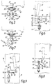
- a pet door 10 embodying the present invention comprises a door frame 11 and a top-hung door flap 12 capable of swinging within the door opening 13.
- the door flap 12 can be swung in either direction about its top hinge axis 12A to allow a pet to pass through the door opening.
- a latch mechanism 14 normally prevents movement of the flap in one direction, A in Fig. 2.
- direction A When installed e.g in a door D of a building, direction A will usually be the inward opening direction.
- inward opening is normally barred
- the latch mechanism 10 in the illustrated embodiment does not hinder opening in the opposite direction B, so pets will have ready egress from the building.
- the latch mechanism 14 can be controlled to enable a pet to push the door flap 12 from engagement with the mechanism 14 and enter the building.
- the latch mechanism 14 is contained in a housing 14A in the base of the frame 11.
- the mechanism itself comprises three principal components. They are: a movable catch 15, a support rocker or cradle 16 and a collapsible support strut 17. This mechanism is disclosed in GB 2 141 479.
- the catch 15 comprises an arm 20 having an upstanding projection 21 at one end normally projecting through an aperture of the housing 14A to engage an edge (for instance the bottom edge) of the flap 12 and prevent inward opening movement in direction A.
- the upstanding projection 21 has a top or ramp surface 22 inclined to its door-engaging face, for a reason to be explained hereafter. Beneath the upstanding projection 21 is a recess 24 in the arm 20; this is to receive the head 25 of the collapsible strut 17. In the normal, latching condition of the mechanism 14, the strut 17 holds the arm 20 in a position such that projection 21 of the catch 15 is raised to prevent opening movement of the flap 12 in direction A.
- recess 26 which is a cylindrical hollow having an inwardly-tapering entrance.
- Recess 24 has a similar form.
- Recess 26 permits the catch 15 to form a snap fit with a pivot pin portion of the cradle 16.
- Intermediate the recesses 24, 26 is means to receive and retain a biasing spring 18, shown as a comparatively shallow recess.
- the cradle 16 has two spaced-apart legs 28 interconnected at one end of the cradle by the pivot pin portion 29.
- the catch 15 is received between the legs 28, with its recess 26 pivotally engaged on pin portion 29.
- Oppositely-directed, aligned stub shafts 30 are provided on the legs 28, adjacent their free ends remote from pivot pin portion 29.
- the stub shafts 30 engage in journals (not shown) suitably provided in the door frame 11.
- the cradle is therefore mounted to rock about an axis through the stub shafts 30, this axis being parallel to the pin portion 29 on which the catch 15 pivots in the cradle.
- the stub shaft axis is closely adjacent the recess 24 seating the head 25 of the strut 17.
- the collapsible strut 17 is a toggle linkage. As is conventional therefore, the toggle strut 17 has two links 17', 17'' pivotally-interconnected at axis 32. One link 17' terminates in the head 25 which seats in the recess 24 of the catch 15. The other link 17'' is apertured at 33 for pivotal mounting to the door frame 11. The pivot axes at 32, 33 are mutually parallel.
- a tension spring 35 extends between an attachment point on link 17'' and a fixed anchorage in the frame 11. The spring 35 biases the toggle strut 17 toward a fixed abutment 36 on the door frame 11.
- a second, displaceable abutment 60 is provided by this invention, and is part of the latch control means.
- the abutment 60 is normally disposed adjacent the interconnection between the links 17', 17'', as shown in Fig. 5. It is displaceable from this position, however, when a key magnet is operatively disposed at the pet door. In its normal, Fig. 5 position, abutment 60 - together with abutment 36 - prevents collapse of the strut 17. In this condition, the strut positively bars downward displacement of the catch 15 about the pivot pin portion 29 and consequential disengagement of upstanding portion 21 from the door flap edge. The strut 17 can be freed so as to collapse away from the abutment 36 and allow the latch mechanism 10 to yield to an inward opening force exerted on the door flap 12, by displacement of abutment 60 to the position shown in Fig. 7. Such displacement occurs when the key magnet is presented to the pet door.
- the biasing spring 18 acts between the door frame, and the assembled catch 15 and cradle 16. It engages these assembled components 15, 16 at a location remote from the pivot axis through the stub shafts 30.
- the spring urges the pivot pin end of the cradle 16 upwardly about the said pivot axis, while affording the cradle an ability to pivot downwardly on its stub shafts 30. Yielding of the spring occurs when the door flap 12 is returning to its closed, Figs. 3 and 5 position after the latch and flap have disengaged and the latter has been opened inwardly.
- the biasing spring could be a leaf spring or a compression spring, but in the preferred embodiment is a spring wire in the shape of a hairpin.
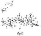
- the latch control means will now be described with particular reference to Fig. 10.
- the control means When activated (by a key magnet) the control means allows the strut 17 to be collapsed when pressure on door flap 12 is exerted in direction A.
- Such pressure is communicated to the upstanding latch portion 21 and has the effect of displacing it downwardly with accompanying collapse of the strut 17.
- portion 21 is displaced into the housing 14A momentarily, allowing the flap 14 to open in direction A.
- the control means 62 comprises the displaceable abutment 60 and a rocking lever (or "see-saw” lever) 64 bearing one or more magnets to coact with the key magnet, 66 in Fig. 10.
- Lever 64 is located inside housing 14A, beneath a sill 68 of the pet door. It is mounted intermediate its ends on a low friction pivot between lugs 70 depending from the top of the housing 14A. The pivot axis 72 is horizontally disposed.
- the lever carries the magnet(s) 74.
- the lever carries a counter-balancing weight 76.
- the lever 64 includes a crank 78 operatively interconnected with the displaceable abutment 60.
- the lever 64 is finely balanced so that it normally disposes the magnets closely beneath the sill 68 and the abutment 60 in position adjacent the fixed abutment 36 to prevent collapse of the strut 17.
- the lever Recognising that a small pet such as a kitten might not approach the pet door centrally, the lever is T-shaped, viewed in plan. It bears two, similarly-poled magnets 74. More preferably, it bears a single elongated magnet, as indicated in dotted lines in Fig. 10.
- the lever could be a simple straight beam bearing a single magnet, however, but would then be more sensitive to the positioning of the key magnet 66.
- the displaceable abutment 60 is a blade projecting from one face of a disc 80 mounted to the door frame 11 via a low-friction rotational mounting 82.
- a pin 84 fast with and projecting from the disc 80 is loosely received in a slot 86 in the lever crank 78.
- the disc lies in a plane spaced from the strut 17, to avoid the disc itself interfering with the strut.
- the disc 80 could be replaced, if desired, by a simple pivoted lever as indicated in dotted lines in Fig. 10.
- control means 62 The constituent parts of the control means 62 are so arranged and balanced that the displaceable abutment 60 is preferably just out of contact with the strut 17 when no key magnet 66 is presented to the pet door.
- An appropriate key magnet 66 is of such polarity as to repel the magnet(s) 74 when it is presented to the pet door, e.g. is brought adjacent or into the confines of the door opening 13.
- end 64' of lever 64 moves downwards (arrow C) and opposite end 64'' moves upwards (arrow D).
- the pin and slot connection 84, 86 between the crank 78 and the disc 80 the latter is rotated about its pivot mounting 82.
- the abutment blade 60 is thereby displaced (in the direction of arrow E) away from its normal operative juxtaposition with the strut 17.
- FIGs. 6 and 7 show the latch mechanism in its condition corresponding to release of the flap for inward opening.
- the flap 12 then swings back in direction B towards its closed position of its own accord. As it swings, the flap edge 48 encounters the upstanding portion 21 of the raised catch 15. For the latch mechanism to lock the flap once more against entry of unwanted animals, the flap must pass the catch 15 to assume the catch-engaging position shown in Figs. 3 and 9. To make this possible, the catch is designed to be cammed downwardly away from the moving flap edge. The camming action results from coaction of the ramped surface 22 with the moving flap 12, and rocking of the cradle 16. The catch is downwardly displaceable due to the camming action despite the strut 17 being erect and braced against the abutment 36. Fig. 8 shows the manner is which the catch is displaceable.
- the strut 17 prevents displacement of catch 15 about pivot pin portion 29. Instead, the catch 15 is momentarily displaced jointly with the cradle 16 by the flap. The assembled catch and cradle rock downwardly thanks to the pivotal attachment of the cradle 16 to the door frame through its stub shafts 30. This displacement is against the bias of spring 18. Once the flap (swinging in direction B) has encountered, displaced and passed the catch 15, the spring 18 will thrust the catch and cradle assembly upwardly about the stub shaft axis. The catch 15 is thereby raised and returned once again to its normal position, when it will prevent inward opening of the flap until such time as key magnet 66 is brought into operative juxtaposition with the lever magnet(s) 74.
- the latch mechanism 10 described above has a very positive action. Before the key magnet 66 repels lever magnet(s) 74, the flap 12 is entirely secure against inward opening, no force exerted thereon being effective to override the catch 15. No significant force is needed however to displace the flap past the catch when the key magnet 66 is operatively placed at the door. Should a key-bearing animal approach the door, decide against entering the building and then move away from the door, the latch mechanism will remain active in barring inward opening of the flap.
- the catch 15 could possess two upstanding portions suitably spaced apart to receive the flap therebetween. With such an arrangement, the latch mechanism 10 could lock the door against opening in either direction in the absence of the key magnet.
- the force needed for displacing the abutment 60 is extremely small.
- the abutment and disc may together only weigh some 1.5 g and it is easy to make the rotational bearing 82 virtually frictionless. Thanks also to the fine balancing of lever 64 and its substantially frictionless pivot mounting, even weak repulsive magnetic forces between the key magnet and the lever magnet(s) will suffice to displace the abutment (60) from its Fig. 5 to its Fig. 7 position. This means that the magnets 66, 74 need not be made strong, large or of costly materials, and adequate range is obtainable from readily available magnets.
- the or each magnet 74 is so poled that the upper face thereof is a north pole.
- the unseen lower face(s) will, of course, be south pole(s).
- the key magnet 66 is so mounted on a pet collar that, as the pet approaches the door, its north pole is leading (arrow F) so as to repel the magnet(s) 74 and thereby rock the lever 64.
- a very modest degree of selectivity could be obtained. That is, two "key differs" are available. Conceivably, two further differs might be obtained.
- the lever 64 carries two magnets 74, the upwardly facing poles thereof could differ (one north and the other south).
- a key magnet disposed as indicated in dotted lines at 66' could effect the required repulsion of the lever magnets if moved towards the door 10 in direction F'.
- the effective range may not be as good with such an arrangement, however, and it would be more prone to non-release should a pet fail to position itself centrally of the door 10.
- the pet doors according to the invention are mainly meant to distinguish owners' pets from other animals e.g. strays, there is a possibility of rendering the doors selective to a degree to reduce the likelihood of neighbours pets being able to enter each others homes to which the present pet doors are fitted.
Landscapes
- Engineering & Computer Science (AREA)
- Civil Engineering (AREA)
- Structural Engineering (AREA)
- Housing For Livestock And Birds (AREA)
Claims (14)
- Eine Tür (10) für ein Haustier mit einem Rahmen (11), der eine Zugangsöffnung (13) bildet, und einer die Öffnung verschließenden Klappe (12), die schwenkbar darin montiert ist, wobei die Tür eine Verriegelungseinrichtung (14) hat, um die Klappe (12) gegen Öffnen wenigstens in einer Richtung zu blockieren, wobei die Verriegelungseinrichtung eine Sperrklinke (15) und eine zusammendrückbare Halterung (17), die so angeordnet ist, daß sie die Sperrklinke (15) in einer die Klappe blockierenden Stellung hält, wenn sie nicht zusammengedrückt ist, und eine Steuerungseinrichtung umfaßt, die eine magnetisch ansprechende Betätigungseinrichtung umfaßt, die so angeordnet ist, daß sie die Steuereinrichtung von einer Position, in der sie das Zusammendrücken der Halterung (17) blockiert, zu einer Position bewegt, die das Zusammendrücken der Halterung (17) nicht blockiert, wenn ein magnetischer Taster (66)der Funktion entsprechend an die Haustiertür (10) geführt wird und dadurch gestattet, daß die Sperrklinke (14) aus ihrer normalen die Klappe blockierenden Stellung bewegt wird, um zu gestatten, daß die Klappe (12) in dieser Richtung geöffnet wird.
- Eine Tür für ein Haustier nach Anspruch 1 in Kombination mit der Tastereinrichtung (66), die z.B. an einem Halsband oder einer Manschette des Haustiers befestigt ist.
- Eine Tür für ein Haustier nach Anspruch 1 oder Anspruch 2, bei der die Verriegelungseinrichtung (14) und die die Betätigungseinrichtung (64) enthaltende Steuereinrichtung (62) innerhalb eines Gehäuses (14A) in dem Rahmen (11) gelegen sind und die Sperrklinkeneinrichtung (15) in einer dafür in dem Rahmen (11) vorgesehenen Öffnung von einer die Klappe blockierenden Stellung, wo sie in die Zugangsöffnung (13) hineinragt, zu einer zurückgezogenen Stellung bewegbar ist, wodurch sich die Klappe (12) in der besagten Richtung öffnen kann.
- Eine Tür für ein Haustier nach einem der Ansprüche 1 bis 3, bei der die zusammendrückbare Halterung (17) durch eine Feder auf einen nicht zusammengedrückten Zustand vorgespannt ist, um die Sperrklinke (15) in der die Klappe blockierenden Stellung zu halten, und die Steuereinrichtung (62) so angeordnet ist, daß sie das Zusammendrücken der Halterung (17) blockiert, bis die Betätigungseinrichtung (64) durch die magnetische Tastereinrichtung (66) aktiviert wird.
- Eine Tür für ein Haustier nach Anspruch 3 oder Anspruch 4, bei der eine Schubkraft, die in der besagten Richtung auf die Klappe (12) ausgeübt wird, so wirkt, daß sie die Sperrklinke (15) verschiebt und die Halterung (17) zusammendrückt, wenn die Betätigungseinrichtung (64) durch die magnetische Tastereinrichtung (66) aktiviert worden ist.
- Eine Tür für ein Haustier nach einem der Ansprüche 3 bis 5, bei der die Steuerungseinrichtung (62) zwei miteinander verbundene, bewegliche Mechanismen (80, 64) umfaßt, von denen einer mit der Halterung (17) normalerweise zusammenwirkt, um zu verhindern, daß sie zusammengedrückt wird, und der andere, der die Betätigungseinrichtung umfaßt, ein wippender oder hin- und herbewegbarer Hebel (64) ist, der einen Magneten (74) hält, wobei der letztere Hebel (64) so angeordnet ist, daß er den anderen Mechanismus (80) bewegt, wenn sein Magnet (74) durch die Tastereinrichtung (66) abgestoßen wird, um diesen besagten anderen Mechanismus (80) aus einer das Zusammendrücken verhindernden Stellung relativ zu der Halterung (17) zu bewegen.
- Eine Tür für ein Haustier nach einem der Ansprüche 3 bis 5, bei der die zusammendrückbare Halterung (17) eine Gelenkhebelverbindung ist, die durch Federkraft gegen eines (36) der zwei benachbarten Endauflager vorgespannt ist und dadurch in einer aufgerichteten, die Sperrklinke stützenden Stellung gehalten wird, wobei das zweite Endauflager (60) von der Gelenkhebelverbindung (17) weg verschiebbar ist, um zu gestatten, daß diese von dem ersten Widerlager (36) durch Betätigung der magnetisch ansprechbaren Betätigungseinrichtung (64) weggedrückt wird.
- Eine Tür für ein Haustier nach Anspruch 7, bei dem das zweite Endauflager (60) von einem Hebel oder einer Scheibe (80) getragen wird, der bzw. die auf einer im wesentlichen reibungsfreien Schwenkhalterung (82) montiert ist, wobei der Hebel oder die Scheibe mechanisch an die Betätigungseinrichtung (64) gekoppelt ist.
- Eine Tür für ein Haustier nach Anspruch 8, bei der die Betätigungseinrichtung ein hin- und herbewegbarer Hebel (64) ist, der auf einem im wesentlichen reibungsfreien Schwenkzapfen (72) angebracht ist, wobei der hin- und herbewegbare Hebel wenigstens einen Magneten (74) trägt, um mit der Tastereinrichtung (66) zusammenwirken zu können.
- Eine Tür für ein Haustier nach Anspruch 9, bei der der wenigstens eine Magnet (74) an einem Ende (64') des hin- und herbewegbaren Hebels (64) vorgesehen ist und der Hebel an seinem anderen, entgegengesetzten Ende (64") mit dem das Endauflager tragenden Hebel oder der Scheibe (80), z.B. durch eine Stift-und-Schlitz-Kupplung (84, 86), verbunden ist.
- Eine Tür für ein Haustier nach einem der vorhergehenden Ansprüche, bei der die Betätigungseinrichtung (64) betätigbar ist, um die Halterung (17) zusammendrücken zu können, wenn sie durch Annäherung der Tastereinrichtung (66) an die Tür (10) magnetisch zurückgestoßen wird.
- Eine Tür für ein Haustier nach Anspruch 7 oder einem von Anspruch 7 abhängigen Anspruch, bei der die Gelenkhebelverbindung (17) ein Paar schwenkbar miteinander verbundener Verbindungsglieder (17',17") aufweist, von denen eines (17') mit der Sperrklinke (15) gekoppelt ist und das andere (17") an einer Schwenkbefestigung auf dem Rahmen (11) befestigt ist und eine Feder (35), die zwischen einem Befestigungspunkt auf einem der Glieder und einer Verankerung auf dem Rahmen (11) gespannt ist, die Gelenkhebelverbindung in Richtung auf das besagte eine Endauflager (36) vorspannt.
- Eine Tür für ein Haustier nach einem der Ansprüche 1 bis 12, bei der die Sperrklinke (15) schwenkbar entfernt von dem zusammendrückbaren Glied (17) auf einem hin- und herbewegbaren Halterungselement (16) montiert ist, welches die Sperrklinke nahe an seinem einen Ende befestigt, wobei das Halteelement (16) so angebracht ist, daß es sich mit der Sperrklinke (15) um eine Achse nahe seines anderen Endes und nahe des zusammendrückbaren Gliedes (17) hin- und herbewegt, und die Anordnung im Gebrauch gestattet, daß die Sperrklinke (15) aus dem Bewegungsweg der Klappe (12) herausbewegt wird, wenn die Klappe zu einer geschlossenen Stellung zurückschwingt, nachdem sie in diese eine Richtung geöffnet worden ist.
- Eine Tür für ein Haustier nach Anspruch 13, die weiterhin Federglieder (18) umfaßt, die die Sperrklinke (15) und das Halteelement (16) in eine Richtung vorspannen, die derjenigen entgegengesetzt ist, in die die Sperrklinke durch die schwingende Klappe (12) verschoben wird.
Applications Claiming Priority (2)
| Application Number | Priority Date | Filing Date | Title |
|---|---|---|---|
| GB9225879 | 1992-12-11 | ||
| GB9225879A GB9225879D0 (en) | 1992-12-11 | 1992-12-11 | Improved pet door |
Publications (2)
| Publication Number | Publication Date |
|---|---|
| EP0601726A1 EP0601726A1 (de) | 1994-06-15 |
| EP0601726B1 true EP0601726B1 (de) | 1997-07-23 |
Family
ID=10726455
Family Applications (1)
| Application Number | Title | Priority Date | Filing Date |
|---|---|---|---|
| EP19930309266 Expired - Lifetime EP0601726B1 (de) | 1992-12-11 | 1993-11-22 | Tür für Haustier |
Country Status (4)
| Country | Link |
|---|---|
| US (1) | US5469659A (de) |
| EP (1) | EP0601726B1 (de) |
| DE (1) | DE69312435T2 (de) |
| GB (1) | GB9225879D0 (de) |
Families Citing this family (24)
| Publication number | Priority date | Publication date | Assignee | Title |
|---|---|---|---|---|
| US5638361A (en) * | 1995-02-08 | 1997-06-10 | Stanford Telecommunications, Inc. | Frequency hopped return link with net entry channel for a satellite personal communications system |
| GB9507167D0 (en) * | 1995-04-06 | 1995-05-31 | Reilor Ltd | Improved pet door |
| USD448088S1 (en) | 2000-04-28 | 2001-09-18 | Reilor Limited | Small pet door |
| US6385909B1 (en) * | 2000-07-31 | 2002-05-14 | Gary F. Marsh | Lockable, cammed door flap for pets |
| US6345946B1 (en) | 2000-08-03 | 2002-02-12 | Radio Systems Corporation | Fastener |
| US20030221631A1 (en) * | 2002-06-03 | 2003-12-04 | Yarbrough Charles J. | Automated pet door system |
| US6959511B2 (en) * | 2003-02-25 | 2005-11-01 | Radio Systems Corporation | Lockable pet door |
| EP1732381B1 (de) | 2004-03-22 | 2013-07-31 | Robert M. Turner | Vorrichtung und verfahren zur tierfütterung |
| US20070051317A1 (en) * | 2005-09-08 | 2007-03-08 | Michael Bruner | Systems and methods for providing selective access to a consumable |
| CA2648114C (en) * | 2006-04-11 | 2016-03-15 | Joseph V. Ambrose | Spring-assisted mechanism for raising and lowering a load |
| GB0619489D0 (en) * | 2006-10-03 | 2006-11-08 | Hill Nicholas P R | RFID pet door |
| US9284773B1 (en) * | 2010-09-28 | 2016-03-15 | Marlene E. Fridley | Locking pet door system |
| US8595976B1 (en) * | 2013-02-08 | 2013-12-03 | Henry E. Solowiej | Gyro-stabilized automatic pet door |
| CN103452464B (zh) * | 2013-09-09 | 2016-03-02 | 石倩文 | 一种具有宠物门的木门 |
| US11060322B2 (en) * | 2015-06-03 | 2021-07-13 | Hti Technology And Industries, Inc. | Powered latching apparatus |
| USD800397S1 (en) * | 2016-02-24 | 2017-10-17 | Dalchand Harripersad | Enclosure |
| US10641021B2 (en) | 2016-09-30 | 2020-05-05 | Barrette Outdoor Living, Inc. | Magnetic safety gate latch |
| US10662686B2 (en) | 2016-09-30 | 2020-05-26 | Barrette Outdoor Living, Inc. | Magnetic safety gate latch |
| US10619389B2 (en) * | 2016-12-20 | 2020-04-14 | Radio Systems Corporation | Pet door having insulating flap |
| US10760305B2 (en) * | 2017-07-07 | 2020-09-01 | Midmark Corporation | Self-locking guillotine door |
| US10941611B2 (en) | 2017-08-18 | 2021-03-09 | Radio Systems Corporation | Pet door |
| EP3669044A4 (de) | 2017-08-18 | 2022-02-09 | Radio Systems Corporation | Elektronische haustierklappe |
| US12421789B2 (en) | 2021-09-02 | 2025-09-23 | Radio Systems Corporation | Pet door |
| US12421792B2 (en) | 2021-09-02 | 2025-09-23 | Radio Systems Corporation | Pet door |
Family Cites Families (8)
| Publication number | Priority date | Publication date | Assignee | Title |
|---|---|---|---|---|
| GB963444A (en) * | 1961-09-12 | 1964-07-08 | Associated Fire Alarms Ltd | Electrically releasable door holding devices |
| US4022263A (en) * | 1976-09-02 | 1977-05-10 | Beckett Richard W | Magnetically actuated cat door |
| GB1567001A (en) * | 1976-12-23 | 1980-05-08 | Dunlop S | Cat ports |
| US4216743A (en) * | 1978-05-30 | 1980-08-12 | Cohen Robert E | Magnetically unlocked pet door |
| GB2141479B (en) * | 1983-06-15 | 1986-12-31 | Reilor Ltd | Self-resetting door latch |
| GB8722627D0 (en) * | 1987-09-25 | 1987-11-04 | Reilor Ltd | Pet doors |
| GB2223257B (en) * | 1988-07-16 | 1992-01-22 | Pet Mate Ltd | Improved electromagnetically controlled cat door |
| GB2236135B (en) * | 1989-09-22 | 1993-08-25 | Pet Mate Ltd | Improvements in cat doors |
-
1992
- 1992-12-11 GB GB9225879A patent/GB9225879D0/en active Pending
-
1993
- 1993-11-22 DE DE69312435T patent/DE69312435T2/de not_active Expired - Fee Related
- 1993-11-22 EP EP19930309266 patent/EP0601726B1/de not_active Expired - Lifetime
- 1993-12-07 US US08/163,664 patent/US5469659A/en not_active Expired - Fee Related
Also Published As
| Publication number | Publication date |
|---|---|
| EP0601726A1 (de) | 1994-06-15 |
| US5469659A (en) | 1995-11-28 |
| DE69312435T2 (de) | 1998-02-26 |
| DE69312435D1 (de) | 1997-09-04 |
| GB9225879D0 (en) | 1993-02-03 |
Similar Documents
| Publication | Publication Date | Title |
|---|---|---|
| EP0601726B1 (de) | Tür für Haustier | |
| EP0736654B1 (de) | Tür für Haustiere | |
| US7765955B2 (en) | Pet door | |
| US4470625A (en) | Emergency exit door latch with hydraulic and electronic delay | |
| US8757677B2 (en) | Lock which can be unlocked in an electrically automated manner, in particular for storage systems like lockers | |
| US5465460A (en) | Doorstop | |
| US7114753B2 (en) | Latch assembly for a sectional door | |
| US5118150A (en) | Compact electric strike | |
| RU2501927C2 (ru) | Предохранительное дверное устройство | |
| US9273505B1 (en) | Automated storm door closure system | |
| WO1995023269A1 (en) | Electromagnetic lock | |
| US6543179B1 (en) | Animal trap | |
| US4572108A (en) | Compact, animal-operated animal feeder | |
| US5611579A (en) | Earthquake activated safety latch | |
| PT1788169E (pt) | CHAPA-TESTA ELéCTRICA | |
| US4596411A (en) | Door locking and monitoring assembly | |
| US4137738A (en) | Time lock with automatic reset | |
| EP0221207A1 (de) | Türdichtungsmechanismus | |
| EP0138423A2 (de) | Automatisches oder handbetätigtes Tor | |
| GB2141479A (en) | Self-resetting door latch | |
| US20210115713A1 (en) | Security device | |
| EP0662553B1 (de) | Türdrückeranordnung | |
| US4167155A (en) | Automatic animal headgate with bottom hinged gates | |
| US7155945B2 (en) | Lock having a lockable handle shaft | |
| JP2969441B2 (ja) | 磁力スイッチ装置及びそれを使用した愛玩動物用扉装置及び愛玩動物用扉装置の開閉方法、愛玩動物の通過制御方法 |
Legal Events
| Date | Code | Title | Description |
|---|---|---|---|
| PUAI | Public reference made under article 153(3) epc to a published international application that has entered the european phase |
Free format text: ORIGINAL CODE: 0009012 |
|
| AK | Designated contracting states |
Kind code of ref document: A1 Designated state(s): BE CH DE FR GB LI LU NL |
|
| 17P | Request for examination filed |
Effective date: 19941119 |
|
| 17Q | First examination report despatched |
Effective date: 19960621 |
|
| GRAG | Despatch of communication of intention to grant |
Free format text: ORIGINAL CODE: EPIDOS AGRA |
|
| GRAH | Despatch of communication of intention to grant a patent |
Free format text: ORIGINAL CODE: EPIDOS IGRA |
|
| GRAH | Despatch of communication of intention to grant a patent |
Free format text: ORIGINAL CODE: EPIDOS IGRA |
|
| GRAA | (expected) grant |
Free format text: ORIGINAL CODE: 0009210 |
|
| AK | Designated contracting states |
Kind code of ref document: B1 Designated state(s): BE CH DE FR GB LI LU NL |
|
| REG | Reference to a national code |
Ref country code: CH Ref legal event code: NV Representative=s name: PATENTANWAELTE SCHAAD, BALASS, MENZL & PARTNER AG Ref country code: CH Ref legal event code: EP |
|
| REF | Corresponds to: |
Ref document number: 69312435 Country of ref document: DE Date of ref document: 19970904 |
|
| ET | Fr: translation filed | ||
| PLBE | No opposition filed within time limit |
Free format text: ORIGINAL CODE: 0009261 |
|
| 26N | No opposition filed | ||
| PGFP | Annual fee paid to national office [announced via postgrant information from national office to epo] |
Ref country code: FR Payment date: 19991012 Year of fee payment: 7 |
|
| PGFP | Annual fee paid to national office [announced via postgrant information from national office to epo] |
Ref country code: LU Payment date: 19991029 Year of fee payment: 7 |
|
| PGFP | Annual fee paid to national office [announced via postgrant information from national office to epo] |
Ref country code: GB Payment date: 19991112 Year of fee payment: 7 Ref country code: BE Payment date: 19991112 Year of fee payment: 7 |
|
| PGFP | Annual fee paid to national office [announced via postgrant information from national office to epo] |
Ref country code: CH Payment date: 19991126 Year of fee payment: 7 |
|
| PGFP | Annual fee paid to national office [announced via postgrant information from national office to epo] |
Ref country code: NL Payment date: 19991130 Year of fee payment: 7 |
|
| PGFP | Annual fee paid to national office [announced via postgrant information from national office to epo] |
Ref country code: DE Payment date: 20000121 Year of fee payment: 7 |
|
| PG25 | Lapsed in a contracting state [announced via postgrant information from national office to epo] |
Ref country code: LU Free format text: LAPSE BECAUSE OF NON-PAYMENT OF DUE FEES Effective date: 20001122 Ref country code: GB Free format text: LAPSE BECAUSE OF NON-PAYMENT OF DUE FEES Effective date: 20001122 |
|
| PG25 | Lapsed in a contracting state [announced via postgrant information from national office to epo] |
Ref country code: LI Free format text: LAPSE BECAUSE OF NON-PAYMENT OF DUE FEES Effective date: 20001130 Ref country code: CH Free format text: LAPSE BECAUSE OF NON-PAYMENT OF DUE FEES Effective date: 20001130 Ref country code: BE Free format text: LAPSE BECAUSE OF NON-PAYMENT OF DUE FEES Effective date: 20001130 |
|
| BERE | Be: lapsed |
Owner name: REILOR HOLDINGS LTD Effective date: 20001130 |
|
| PG25 | Lapsed in a contracting state [announced via postgrant information from national office to epo] |
Ref country code: NL Free format text: LAPSE BECAUSE OF NON-PAYMENT OF DUE FEES Effective date: 20010601 |
|
| GBPC | Gb: european patent ceased through non-payment of renewal fee |
Effective date: 20001122 |
|
| REG | Reference to a national code |
Ref country code: CH Ref legal event code: PL |
|
| PG25 | Lapsed in a contracting state [announced via postgrant information from national office to epo] |
Ref country code: FR Free format text: LAPSE BECAUSE OF NON-PAYMENT OF DUE FEES Effective date: 20010731 |
|
| NLV4 | Nl: lapsed or anulled due to non-payment of the annual fee |
Effective date: 20010601 |
|
| REG | Reference to a national code |
Ref country code: FR Ref legal event code: ST |
|
| PG25 | Lapsed in a contracting state [announced via postgrant information from national office to epo] |
Ref country code: DE Free format text: LAPSE BECAUSE OF NON-PAYMENT OF DUE FEES Effective date: 20011101 |