EP0601432A2 - Method and system for estimating inertia of 2-mass system during speed control - Google Patents
Method and system for estimating inertia of 2-mass system during speed control Download PDFInfo
- Publication number
- EP0601432A2 EP0601432A2 EP93119206A EP93119206A EP0601432A2 EP 0601432 A2 EP0601432 A2 EP 0601432A2 EP 93119206 A EP93119206 A EP 93119206A EP 93119206 A EP93119206 A EP 93119206A EP 0601432 A2 EP0601432 A2 EP 0601432A2
- Authority
- EP
- European Patent Office
- Prior art keywords
- load torque
- estimate
- speed
- observer
- motor
- Prior art date
- Legal status (The legal status is an assumption and is not a legal conclusion. Google has not performed a legal analysis and makes no representation as to the accuracy of the status listed.)
- Granted
Links
Images


Classifications
-
- H—ELECTRICITY
- H02—GENERATION; CONVERSION OR DISTRIBUTION OF ELECTRIC POWER
- H02P—CONTROL OR REGULATION OF ELECTRIC MOTORS, ELECTRIC GENERATORS OR DYNAMO-ELECTRIC CONVERTERS; CONTROLLING TRANSFORMERS, REACTORS OR CHOKE COILS
- H02P5/00—Arrangements specially adapted for regulating or controlling the speed or torque of two or more electric motors
-
- H—ELECTRICITY
- H02—GENERATION; CONVERSION OR DISTRIBUTION OF ELECTRIC POWER
- H02P—CONTROL OR REGULATION OF ELECTRIC MOTORS, ELECTRIC GENERATORS OR DYNAMO-ELECTRIC CONVERTERS; CONTROLLING TRANSFORMERS, REACTORS OR CHOKE COILS
- H02P29/00—Arrangements for regulating or controlling electric motors, appropriate for both AC and DC motors
- H02P29/0016—Control of angular speed of one shaft without controlling the prime mover
Definitions
- the present invention relates to a method and system for estimating an inertia of torsionally vibrating 2-mass system in a speed control.
- 2-mass system is constituted by a motor and a load connected through a low rigidity shaft (elastic shaft) in an elevator, rolling mill of steel or arm of robot
- the 2-mass system generates a shaft torsional vibration and cannot be improved in responsibility of a speed control system.
- a shaft torsional vibration is effected by a ratio between inertia of moments of the motor and the load.
- the vibration tends to be generated when the moment of inertia of the load is smaller than that of the motor.
- an inertia of 1-mass system (a motor) is estimated by a speed-accelerating test of a motor. Then, after the connection of a load with the motor, the 2-mass system is gradually accelerated so as not to generate a vibration, and under this condition an inertia of the 2-mass (motor + load) system is estimated.
- An aspect of the present invention resides in a method of estimating an inertia of 2-mass system in a speed control system for controlling the 2-mass system of a motor and a load connected through an elastic shaft.
- the speed control system comprises a speed control amplifier which amplifies a deviation between a preset speed and a motor speed, a load torque estimate observer which obtains a load torque estimate, and a model machine control system which outputs a load torque command upon receiving the sum of the output of the speed control amplifier and the load torque estimate. Further, the speed control system controls the 2-mass system according to the torque command.
- the method comprises the following steps: (a) obtaining an observer speed estimate from an integral factor which has a model machine time constant of the sum of a machine time constant of the motor and a machine time constant of the load, by inputting a deviation between the load torque estimate and a load torque equivalent value into the integral factor; and (b) estimating the inertia of the 2-mass system by dividing the observer speed estimate by the motor speed.
- the speed control system comprises a speed control amplifier which amplifies a deviation between a preset speed and a motor speed, a load torque estimate observer which obtains a load torque estimate, and a model machine control system which outputs a load torque command upon receiving the sum of the output of the speed control amplifier and the load torque estimate, the speed control system controlling the 2-mass system according to the torque command, said system comprising: means for outputting an observer speed estimate from a first integral factor which has a model machine time constant of the sum of a machine time constant of a motor and a machine time constant of a load in such a manner to input a deviation between the load torque estimate and the load torque equivalent value into the integral factor; and means for estimating the inertia of the 2-mass system in such a manner to divide the output from the integral factor by
- Fig. 14 shows an explanatory view which shows a model of 2-mass system.
- the 2-mass system comprises a motor M and a load L which are connected through an elastic shaft S.
- ⁇ M is a motor generating torque
- ⁇ M is a motor angle speed
- ⁇ L is a load torque
- ⁇ L is an angle speed of load L
- ⁇ S is a shaft torque.
- n M ( ⁇ M - ⁇ S )/T M S (1)
- n L ( ⁇ S - ⁇ L )/T L S (2)
- ⁇ S (n M - n L )/T s S (3)
- n M is a motor speed
- n L is a load speed
- Fig. 15 shows a block diagram of the 2-mass system of Fig. 14.
- T M denotes a time constant of a machine of motor
- T L denotes a machine time constant of load
- T S denotes a time constant of a spring.
- the equation (6) is obtained.
- the load torque estimate becomes equal to the load torque That is to say, when the 2-mass system is approximated to the 1-mass system and when the load torque ⁇ L is estimated by using the load torque observer, such equal condition is obtained under the stationary state. Accordingly, by keeping the load torque estimate which is in a stable state under non-acceleration condition as is similar to in the 1-mass system, it becomes possible to almost accurately estimate the load torque ⁇ L .
- the third term of the right side in the equation (8) has no effect to the inertia error K-1. Therefore, an inertia error estimating circuit applied to the 1-mass system may be applied to the 2-mass system. Accordingly, the equation (8) may be approximated by the after-mentioned equation (9).
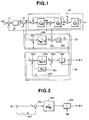
- Fig. 1 shows a first embodiment of the inertia estimating circuit of the torsionally vibrating 2-mass system according to the present invention.
- reference numeral 11 is a deviation section which obtains the deviation between the motor speed command n M * and the motor speed n M .
- the output of the deviation section 11 is inputted into a speed control amplifier 12.
- the output i A * of the speed control amplifier 12 is inputted into the adding section 13 wherein The output i A * of the speed control amplifier 12 is added with the load torque estimate .
- the output of the adding section 13 is treated as a motor generating torque ⁇ M and is supplied to a 2-mass system model 14 shown in Fig. 15.
- the motor generating torque ⁇ M is inputted into the load torque estimating observer 15 wherein the load torque estimate is obtained.
- the load torque estimating observer 15 comprises a deviation section 15a which detects a deviation between the motor generating torque ⁇ M and the load torque estimate .
- the output of the deviation section 15a is supplied to an integration section 15b which is constituted by a time constant of the model machine.
- a deviation section 15c obtains a deviation between the output of the integration section 15b and the motor speed n M .
- the output of the deviation section 15c is supplied to an observer gain section 15d where the load torque estimate outputted.
- the load torque estimate from the load torque estimating observer 15 is supplied to the inertia error estimating section 16.
- the inertia error estimating section 16 comprises a deviation section 16a to which the load torque estimate and the load torque equivalent value ⁇ L ' are supplied.
- the output of the deviation section 16a is supplied to an integration section 16c constituted by a model machine time constant and an inverse-number section 16c for the observer gain. Both outputs of the integral factor 16b and the inverse-number section 16d are inputted into an adding section 16d.
- the output of the adding section 16d is divided by the motor speed n M in a dividing section 16e.
- a switch section 16f for obtaining the load torque equivalent value ⁇ L ' is installed in the inertia error estimating section 16.
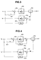
- Fig. 2 shows a second embodiment of the inertia torque estimating circuit according to the present invention.
- the observer gain inverse-number section 16c of the inertia error estimating section 16 be omitted as shown in Fig. 2.
- Fig. 3 there is shown a third embodiment of the inertia estimating circuit according to the present invention.
- the third embodiment is a deformation of the second embodiment. That is, the third embodiment further comprises a second integral factor 16g which is constituted by a model machine time constant of the sum of the machine time constants of the motor and the load. An observer-gain inverse-number section 16h and a deviation section 16i are further added to the inertia error estimating section 16. The second integration section receives the output i A * of the speed control amplifier 12.
- FIG. 4 there is shown a fourth embodiment of the inertia estimating circuit according to the present invention.
- the fourth embodiment comprises a second integration factor 16g , an observer gain inverse number section 16h and a deviation section 16i in the inertia error estimating section 16 of the third embodiment.
- Figs. 5 and 6 are characteristic graphs which show examples of simulation of the inertia error estimation of the torsionally vibrating 2-mass system.
- Fig. 7 shows a detector circuit which is used to judge that the system in the speed-adjusting condition (accelerating or decelerating condition) when the output i A * of the speed control amplifier 12 is greater than a predetermined value.
- the detector circuit comprises an absolute value circuit 71 and a filter 72 for taking an overshoot and an undershoot of the output i A * into consideration.
- F of the filter 71 are transferred through an OR circuit 73 to a comparator 74 wherein the outputs are compared with a speed-adjusting detection set value.
- a signal indicative that the 2-mass system is now in a speed-adjusting condition is outputted from the comparator 74, and in reply to the signal a switch 16f is opened. Accordingly, the load torque estimate is held and therefore the lead torque equivalent value ⁇ L ' ,which keeps stable, is obtained.
- the above-mentioned embodiment is an inertia error (K-1) estimating section.
- the motor speed estimate is obtained by the following equation (13):
- the load torque ⁇ L in the equations (11) and (12) can be treated as the load torque equivalent value ⁇ L '.
- the inertia ratio K (T M + T L ) / T ML * is obtained by using the equations (12) and (13) as follows: This is the same result as that of the 1-mass system.
- Fig. 8 shows a fifth embodiment of the inertia estimating circuit according to the present invention.
- an inertia ratio estimating section 17 comprises a deviation section 17a, an integral factor 17b, a dividing section 17c and a switch 17d.
- the deviation section 17a outputs a deviation between the motor generating torque n M and the load torque equivalent value ⁇ L '.
- the integral factor 17b is constituted by a model machine time constant (the sum of the machine time constant of the motor and the machine time constant of the load) and outputs the motor speed estimate according to the output of the deviation section 17a.
- the dividing section 17c divides the motor speed estimate by the motor speed n M and outputs the inertia ratio K.
- Fig. 9 shows a sixth embodiment of the inertia estimating system according to the present invention.
- the sixth embodiment is different from the fifth embodiment in the inertia ratio estimating section 17.
- the inertia ratio estimating section 17 of the sixth embodiment comprises an adding section 17e.
- the output iA* of the speed control amplifier 12 is applied to an input end of the adding section 17e.
- the load torque estimate is applied to the other input end of the adding section 17e.
- the adding section 17e outputs the motor generating torque ⁇ M to the deviation section 17a.
- Fig. 10 shows a seventh embodiment which is arranged such that a second integral factor 17f, an observer gain inverse number section 17g and a deviation section 17h are further added in the inertia ratio estimating section of the sixth embodiment.
- the second integral factor 17f receives the output i A * of the speed control amplifier 12, and the observer gain inverse number section 17g receives the load torque estimate .
- the outputs of the second integral factor 17f and the observer gain inverse number section 17g is inputted into the deviation section 17h which outputs the motor speed n M .
- eighth and ninth embodiments are arranged to have an inertia ratio estimating section where the load torque estimate is not added to the torque current command i T *.
- Fig. 11 shows the eighth embodiment of the inertia estimating circuit according to the present invention.
- a current control system 21 receives the output i A * of the speed control amplifier 12 and outputs a torque current i T .
- the torque current is inputted to a constant section 22 of a torque coefficient K ⁇ , and the torque command ⁇ M is outputted from the constant section 22.
- a deviation section 23 receives the torque command ⁇ M and the load torque ⁇ L , and outputs the deviation to a 2-mass system model 14.
- reference numeral 15e is a constant section of the model value K ⁇ * of the torque coefficient
- 15f is an inverse number section of the model value K ⁇ *.
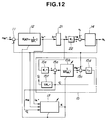
- Fig. 12 shows the ninth embodiment of the inertia estimating circuit according to the present invention.
- auto-tuning of the motor speed control system is implemented by applying the variation K of the inertia ratio estimating section 17 to the model machine time constant 15b of the load torque estimating observer 15 and the speed control amplifier 12.
- a speed-adjusting period detecting circuit as shown in Fig. 13A is used.
- a signal indicative that the speed-adjusting is now implemented is ouputted as shown in Fig. 13B.
- Both of tenth and eleventh embodiments of the inertia estimating circuit comprise an inertia estimating section where the load torque estimate is not added to the torque current command i T * as is similar to the eighth and ninth embodiments.
- Fig. 16 shows the tenth embodiment wherein it is arranged such that the load torque estimate is not added to the output of the speed control amplifier 12 of the fifth embodiment of Fig. 8.
- Fig. 17 shows the eleventh embodiment wherein it is arranged such that the load torque estimate is not added to the output of the speed control amplifier 12 of the first embodiment of Fig. 1. It will be understood that in the eleventh embodiment the inverse number section 16c of the observer gain in the inertia estimating section may be removed and then the construction of the inertia error estimating section 16 becomes the same as that in Fig. 2. Also, the speed-adjusting period detecting circuit as shown in Fig. 13A is used in the tenth and eleventh embodiments as is similar to that in the eighth and ninth embodiments since the load torque estimate is not added to the output of the speed control amplifier 12 in the tenth and eleventh embodiments.
Landscapes
- Engineering & Computer Science (AREA)
- Power Engineering (AREA)
- Control Of Electric Motors In General (AREA)
Abstract
Description
- The present invention relates to a method and system for estimating an inertia of torsionally vibrating 2-mass system in a speed control.
- It is well known that if 2-mass system is constituted by a motor and a load connected through a low rigidity shaft (elastic shaft) in an elevator, rolling mill of steel or arm of robot, the 2-mass system generates a shaft torsional vibration and cannot be improved in responsibility of a speed control system. Further, such a shaft torsional vibration is effected by a ratio between inertia of moments of the motor and the load. In particular, the vibration tends to be generated when the moment of inertia of the load is smaller than that of the motor. Although a conventional method, which uses a load torque estimating observer, has been proposed for the control of the 2-mass system, the method does not have a large effect for suppressing the shaft torsional vibration when the moment of inertia of the load is smaller than that of the motor.
- Furthermore, in order to effectively suppress the torsional vibration of the 2-mass system, a method for estimating inertia of the 2-mass system has been proposed. In this method, first, an inertia of 1-mass system (a motor) is estimated by a speed-accelerating test of a motor. Then, after the connection of a load with the motor, the 2-mass system is gradually accelerated so as not to generate a vibration, and under this condition an inertia of the 2-mass (motor + load) system is estimated.
- However, such a conventional estimating method is not useful in a system which is applied to a condition that a load inertia is deviated during operation, such as, to a robot arm or an elevator since the conventional estimating method cannot implement the estimation of the 2-mass system which generates a torsional vibration during operation.
- It is an object of the present invention to provide an inertia estimating method and system which enable the estimation of inertia of torsionally vibrating 2-mass system even if it is applied to a condition that a load inertia is deviated during operation.
- An aspect of the present invention resides in a method of estimating an inertia of 2-mass system in a speed control system for controlling the 2-mass system of a motor and a load connected through an elastic shaft. The speed control system comprises a speed control amplifier which amplifies a deviation between a preset speed and a motor speed, a load torque estimate observer which obtains a load torque estimate, and a model machine control system which outputs a load torque command upon receiving the sum of the output of the speed control amplifier and the load torque estimate. Further, the speed control system controls the 2-mass system according to the torque command. In the speed control system, the method comprises the following steps: (a) obtaining an observer speed estimate from an integral factor which has a model machine time constant of the sum of a machine time constant of the motor and a machine time constant of the load, by inputting a deviation between the load torque estimate and a load torque equivalent value into the integral factor; and (b) estimating the inertia of the 2-mass system by dividing the observer speed estimate by the motor speed.
- Another aspect of the present invention resides in a system for estimating an inertia of 2-mass system in a speed control system for controlling the 2-mass system of a motor and a load connected through an elastic shaft. The speed control system comprises a speed control amplifier which amplifies a deviation between a preset speed and a motor speed, a load torque estimate observer which obtains a load torque estimate, and a model machine control system which outputs a load torque command upon receiving the sum of the output of the speed control amplifier and the load torque estimate, the speed control system controlling the 2-mass system according to the torque command, said system comprising: means for outputting an observer speed estimate from a first integral factor which has a model machine time constant of the sum of a machine time constant of a motor and a machine time constant of a load in such a manner to input a deviation between the load torque estimate and the load torque equivalent value into the integral factor; and means for estimating the inertia of the 2-mass system in such a manner to divide the output from the integral factor by the motor speed.
- In the drawings, like reference numerals designate like parts and like elements throughout all figures, in which:
- Fig. 1 is a block diagram showing a first embodiment of an inertia estimating circuit of a speed controller in 2-mass torsional vibration system;
- Fig. 2 is a block diagram which shows a second embodiment of the inertia estimating circuit;
- Fig. 3 is a block diagram which shows a third embodiment of the inertia estimating circuit;
- Fig. 4 is a block diagram which shows a fourth embodiment of the inertia estimating circuit;
- Fig. 5 and 6 show characteristic views which show examples of a simulation of the estimation of the inertia error of the 2-mass torsional vibration system;
- Fig. 7 is a block diagram which shows a detector circuit for detecting a speed-adjusting condition;
- Fig. 8 is a block diagram which shows a fifth embodiment of the inertia estimating circuit;
- Fig. 9 is a block diagram which shows a sixth embodiment of the inertia estimating circuit;
- Fig. 10 is a block diagram which shows a seventh embodiment of the inertia estimating circuit;
- Fig. 11 is a block diagram which shows an eighth embodiment of the inertia estimating circuit;
- Fig. 12 is a block diagram which shows a ninth embodiment of the inertia estimating circuit;
- Fig. 13A is a block diagram of a detector circuit for detecting a variation ratio, and Fig. 13B is a wave form view;
- Fig. 14 is an explanatory view of a model of a 2-mass system;
- Fig. 15 is a block diagram of the 2-mass system of Figs. 13A and 13B;
- Fig. 16 is a block diagram of a tenth embodiment of the inertia estimating circuit; and
- Fig. 17 is a block diagram of an eleventh embodiment of the inertia estimating circuit.
- Reference will hereinafter be made to drawings in order to facilitate a better understanding of the present invention.
- First, it will be discussed that a method of estimating inertia of 1-mass system by using a load torque observer is applicable to 2-mass system.
- Hereinafter, a principle of the inertia error estimation in 2-mass system will be discussed. Fig. 14 shows an explanatory view which shows a model of 2-mass system. The 2-mass system comprises a motor M and a load L which are connected through an elastic shaft S. In Fig. 14, τM is a motor generating torque, ωM is a motor angle speed, τL is a load torque, ωL is an angle speed of load L, and τS is a shaft torque.
- On the basis of the model of 2-mass system shown in Fig. 14, the equations of motion thereof are obtained as follows:


where nM is a motor speed, and nL is a load speed. - Fig. 15 shows a block diagram of the 2-mass system of Fig. 14. In Fig. 15, TM denotes a time constant of a machine of motor, TL denotes a machine time constant of load, and TS denotes a time constant of a spring.
- When the above-mentioned 2-mass system by a motor and a load inertia is approximated by 1-mass system, a load torque estimate, which is estimated by a load torque estimating observer, is represented by the following equation (4):


wherein TML* is a model machine time constant of (TM + TL),
- By using the equations (1) and (2), the motor generating torque τM is represented by the following equation (5):

By substitute the equation (5) for the equation (4), the following equation (6) is obtained.
When an inertia sum-ratio of the real machine and the model is

In case that nM = constant in the equation (7), since it is assumed that the system has no-vibration and keeps stable, the motor speed nM equals to the load speed nL ( becomes equal to the load torque
That is to say, when the 2-mass system is approximated to the 1-mass system and when the load torque τL is estimated by using the load torque observer, such equal condition
is obtained under the stationary state. Accordingly, by keeping the load torque estimatewhich is in a stable state under non-acceleration condition as is similar to in the 1-mass system, it becomes possible to almost accurately estimate the load torque τL. - In the equation (7), when it is assumed that the load torque is not varied during the inertia estimation (during the acceleration operation) while holding data during a stable condition which data is obtained by the load torque estimateas a load torque equivalent value τL', it may be treated that


When it is possible to reduce the torsional vibration by means of a correction of the observer, the motor speed nM equals to the load speed nL (
- Fig. 1 shows a first embodiment of the inertia estimating circuit of the torsionally vibrating 2-mass system according to the present invention.
- In Fig. 1, reference numeral 11 is a deviation section which obtains the deviation between the motor speed command nM* and the motor speed nM. The output of the deviation section 11 is inputted into a
speed control amplifier 12. The output iA* of thespeed control amplifier 12 is inputted into the addingsection 13 wherein The output iA* of thespeed control amplifier 12 is added with the load torque estimate. The output of the addingsection 13 is treated as a motor generating torque τM and is supplied to a 2-mass system model 14 shown in Fig. 15. The motor generating torque τM is inputted into the loadtorque estimating observer 15 wherein the load torque estimateis obtained. - The load
torque estimating observer 15 comprises adeviation section 15a which detects a deviation between the motor generating torque τM and the load torque estimate. The output of thedeviation section 15a is supplied to anintegration section 15b which is constituted by a time constant of the model machine. Adeviation section 15c obtains a deviation between the output of theintegration section 15b and the motor speed nM. The output of thedeviation section 15c is supplied to anobserver gain section 15d where the load torque estimateoutputted. - The load torque estimatefrom the load
torque estimating observer 15 is supplied to the inertiaerror estimating section 16. The inertiaerror estimating section 16 comprises adeviation section 16a to which the load torque estimateand the load torque equivalent value τL' are supplied. The output of thedeviation section 16a is supplied to anintegration section 16c constituted by a model machine time constant and an inverse-number section 16c for the observer gain. Both outputs of theintegral factor 16b and the inverse-number section 16d are inputted into an addingsection 16d. The output of the addingsection 16d is divided by the motor speed nM in adividing section 16e. Aswitch section 16f for obtaining the load torque equivalent value τL' is installed in the inertiaerror estimating section 16. - Assuming that the load torque is kept constant, the load torque estimatebecomes equal to the load torque equivalent value

under a stationary state. Accordingly, the second term of the right side of the equation (9) is negligible. - Fig. 2 shows a second embodiment of the inertia torque estimating circuit according to the present invention. In the second embodiment, the observer gain inverse-
number section 16c of the inertiaerror estimating section 16 be omitted as shown in Fig. 2.
Referring to Fig. 3, there is shown a third embodiment of the inertia estimating circuit according to the present invention. - The third embodiment is a deformation of the second embodiment. That is, the third embodiment further comprises a second
integral factor 16g which is constituted by a model machine time constant of the sum of the machine time constants of the motor and the load. An observer-gain inverse-number section 16h and adeviation section 16i are further added to the inertiaerror estimating section 16. The second integration section receives the output iA* of thespeed control amplifier 12. - Referring to Fig. 4, there is shown a fourth embodiment of the inertia estimating circuit according to the present invention.
- The fourth embodiment comprises a
second integration factor 16g , an observer gaininverse number section 16h and adeviation section 16i in the inertiaerror estimating section 16 of the third embodiment. - Figs. 5 and 6 are characteristic graphs which show examples of simulation of the inertia error estimation of the torsionally vibrating 2-mass system. Fig. 5 shows the characteristic curves of iA*,, and τL' when


- Fig. 7 shows a detector circuit which is used to judge that the system in the speed-adjusting condition (accelerating or decelerating condition) when the output iA* of the
speed control amplifier 12 is greater than a predetermined value. The detector circuit comprises anabsolute value circuit 71 and afilter 72 for taking an overshoot and an undershoot of the output iA* into consideration. - The output | iA | of the absolute circuit and the output | iA | F of the
filter 71 are transferred through an ORcircuit 73 to acomparator 74 wherein the outputs are compared with a speed-adjusting detection set value. When the output from theOR circuit 73 is larger than the speed-adjusting detection set value, a signal indicative that the 2-mass system is now in a speed-adjusting condition (accelerating or decelerating condition) is outputted from thecomparator 74, and in reply to the signal aswitch 16f is opened. Accordingly, the load torque estimate is held and therefore the lead torque equivalent value τL' ,which keeps stable, is obtained. - The above-mentioned embodiment is an inertia error (K-1) estimating section.
- A principle of the estimation of an inertia ratio of the 2-mass system will be discussed hereinafter.
- First, a method for directly estimating an inertia ratio K which is studied in the 1-mass system will be explained. By combining the equations (1) and (2), the following equation (10) is obtained.

From the equation (10), the following equation (11) is obtained.
Assuming that the condition of the system is finally converged into a stable no-vibration condition even if a vibration is occurred during the speed-adjusting period,

By approximating the motor + load inertia of the 2-mass system to the 1-mass system, the motor speed estimateis obtained by the following equation (13):

In this situation, when stable data of the load torque estimate, which is obtained by the lead torque estimate observer as is similar to the fourth embodiment, is approximated to the load torque τL, the load torque τL in the equations (11) and (12) can be treated as the load torque equivalent value τL'. Accordingly, the inertia ratio

This is the same result as that of the 1-mass system. - Fig. 8 shows a fifth embodiment of the inertia estimating circuit according to the present invention.
- According to the above-obtained result, an estimating section of the inertia ratio K of the 2-mass system is described as shown the fifth embodiment. As shown in Fig. 8, an inertia
ratio estimating section 17 comprises adeviation section 17a, anintegral factor 17b, adividing section 17c and aswitch 17d. Thedeviation section 17a outputs a deviation between the motor generating torque nM and the load torque equivalent value τL'. Theintegral factor 17b is constituted by a model machine time constant (the sum of the machine time constant of the motor and the machine time constant of the load) and outputs the motor speed estimateaccording to the output of thedeviation section 17a. Thedividing section 17c divides the motor speed estimateby the motor speed nM and outputs the inertia ratio K. - Fig. 9 shows a sixth embodiment of the inertia estimating system according to the present invention.
- The sixth embodiment is different from the fifth embodiment in the inertia
ratio estimating section 17. The inertiaratio estimating section 17 of the sixth embodiment comprises an addingsection 17e. The output iA* of thespeed control amplifier 12 is applied to an input end of the addingsection 17e. The load torque estimateis applied to the other input end of the addingsection 17e. The addingsection 17e outputs the motor generating torque τM to thedeviation section 17a. - Fig. 10 shows a seventh embodiment which is arranged such that a second integral factor 17f, an observer gain
inverse number section 17g and adeviation section 17h are further added in the inertia ratio estimating section of the sixth embodiment. The second integral factor 17f receives the output iA* of thespeed control amplifier 12, and the observer gaininverse number section 17g receives the load torque estimate. The outputs of the second integral factor 17f and the observer gaininverse number section 17g is inputted into thedeviation section 17h which outputs the motor speed nM. - Although the above-mentioned embodiments have been arranged such that the torque current command iT* is outputted by adding the load torque estimatefrom the observer gain
inverse section 17g and the output iA* of thespeed control amplifier 12, eighth and ninth embodiments are arranged to have an inertia ratio estimating section where the load torque estimateis not added to the torque current command iT*. - Fig. 11 shows the eighth embodiment of the inertia estimating circuit according to the present invention.
- As shown in Fig. 11, a
current control system 21 receives the output iA* of thespeed control amplifier 12 and outputs a torque current iT. The torque current is inputted to aconstant section 22 of a torque coefficient Kτ, and the torque command τM is outputted from theconstant section 22. Adeviation section 23 receives the torque command τM and the load torque τL, and outputs the deviation to a 2-mass system model 14. In the loadtorque estimating observer 15,reference numeral 15e is a constant section of the model value Kτ* of the torque coefficient, and 15f is an inverse number section of the model value Kτ*. - Fig. 12 shows the ninth embodiment of the inertia estimating circuit according to the present invention. In this embodiment, auto-tuning of the motor speed control system is implemented by applying the variation K of the inertia
ratio estimating section 17 to the model machine time constant 15b of the loadtorque estimating observer 15 and thespeed control amplifier 12. - In Figs. 11 and 12, since the load torque estimateis not added to the output iA* of the
speed control amplifier 12, a speed-adjusting period detecting circuit as shown in Fig. 13A is used. When the change of the motor speed nM is larger than a variation preset value in Fig. 13A , a signal indicative that the speed-adjusting is now implemented is ouputted as shown in Fig. 13B. - Both of tenth and eleventh embodiments of the inertia estimating circuit comprise an inertia estimating section where the load torque estimateis not added to the torque current command iT* as is similar to the eighth and ninth embodiments.
- Fig. 16 shows the tenth embodiment wherein it is arranged such that the load torque estimateis not added to the output of the
speed control amplifier 12 of the fifth embodiment of Fig. 8. - Fig. 17 shows the eleventh embodiment wherein it is arranged such that the load torque estimateis not added to the output of the
speed control amplifier 12 of the first embodiment of Fig. 1. It will be understood that in the eleventh embodiment theinverse number section 16c of the observer gain in the inertia estimating section may be removed and then the construction of the inertiaerror estimating section 16 becomes the same as that in Fig. 2. Also, the speed-adjusting period detecting circuit as shown in Fig. 13A is used in the tenth and eleventh embodiments as is similar to that in the eighth and ninth embodiments since the load torque estimateis not added to the output of thespeed control amplifier 12 in the tenth and eleventh embodiments. - With the thus arranged embodiments, it becomes possible to estimate the inertia of the torsionally vibrating 2-mass system which generates a deviation of the load inertia during operation. Furthermore, even if the 2-mass torsional vibration is occurred in the system, if the vibration is converged, it is possible to estimate the inertia of the system.
Claims (19)
- A method of estimating an inertia of 2-mass system in a speed control system for controlling the 2-mass system of a motor and a load connected through an elastic shaft, the speed control system comprising a speed control amplifier which amplifies a deviation between a preset speed and a motor speed, a load torque estimate observer which obtains a load torque estimate, and a model machine control system which outputs a load torque command upon receiving the sum of the output of the speed control amplifier and the load torque estimate, the speed control system controlling the 2-mass system according to the torque command, said method comprising by steps:(a) obtaining an observer speed estimate from an integral factor which has a model machine time constant of the sum of a machine time constant of the motor and a machine time constant of the load, by inputting a deviation between the load torque estimate and a load torque equivalent value into the integral factor; and(b) estimating the inertia of the 2-mass system by dividing the observer speed estimate by the motor speed.
- A method of estimating an inertia of 2-mass system in a speed control system for controlling the 2-mass system of a motor and a load connected through an elastic shaft, the speed control system comprising a speed control amplifier which amplifies a deviation between a preset speed and a motor speed, a load torque estimate observer which obtains a load torque estimate, and a model machine control system which outputs a load torque command upon receiving the sum of the output of the speed control amplifier and the load torque estimate, the speed control system controlling the 2-mass system according to the load torque command, said method comprising by steps:(a) obtaining an observer speed estimate from a first integral factor which has a model machine time constant of the sum of a machine time constant of the motor and a machine time constant of the load by inputting a deviation between the load torque estimate and a load torque equivalent value into the first integral factor;(b) obtaining an output from a second integral factor which has a model machine time constant of the sum of the machine time constant of the motor and the machine time constant of the load by inputting the output of the speed control amplifier;(c) obtaining a motor speed from a deviation between the output of the second integral factor and an output of an observer-gain inverse-number section to which the output of the speed control amplifier; and(d) estimating an inertia of the 2-mass system by dividing the observer speed estimate by the motor speed.
- A method as claimed in Claim 1, wherein an observer-gain inverse-number section is disposed parallel with the integral factor, an output of the observer-gain inverse-number section is added to the output of the integral factor.
- A method as claim in Claim 2, wherein an observer-gain inverse-number section is disposed parallel with the first integral factor, the output of the observer-gain inverse-number section is added to the output of the first integral factor.
- A method as claimed in Claim 1, wherein the deviation to be inputted into the integral factor is obtained from the deviation between the load torque equivalent value and the sum of the output of the speed control amplifier and the load torque estimate.
- A method as claimed in Claim 2, wherein the deviation to be inputted into the first integral factor is obtained from the deviation between the load torque equivalent value and the sum of the output of the speed control amplifier and the load torque estimate.
- A method of estimating an inertia of 2-mass system in a speed control system for controlling the 2-mass system of a motor and a load connected through an elastic shaft, said method comprising by steps:(a) obtaining a load torque estimate by using a load torque estimating observer,(b) obtaining a load torque equivalent value from the load torque estimate;(c) obtaining an observer speed estimate by inputting the deviation between the torque command and the load torque equivalent value into an integral factor of a model machine time constant constituted by the sum of machine time constants of the motor and the load; and(d) estimating an inertia of the 2-mass system by dividing the observer speed estimate by the motor speed in a dividing section.
- A method of estimating an inertia of 2-mass system in a speed control system for controlling the 2-mass system of a motor and a load connected through an elastic shaft, said method comprising by steps:(a) obtaining a load torque estimate by using a load torque estimating observer;(b) obtaining an observer speed estimate by inputting a deviation between the load torque estimate and the load torque equivalent value into an integral factor which has a model machine time constant of the sum of time constants of the motor and the load; and(c) estimating an inertia of the 2-mass system by dividing the observer speed estimate by the motor speed.
- A method as claimed in Claim 8, wherein an observer-gain inverse-number section is disposed parallel with the integral factor, an output of the observer-gain inverse-number section is added to the output of the integral factor.
- A system for estimating an inertia of 2-mass system in a speed control system for controlling the 2-mass system of a motor and a load connected through an elastic shaft, the speed control system comprising a speed control amplifier which amplifies a deviation between a preset speed and a motor speed, a load torque estimate observer which obtains a load torque estimate, and a model machine control system which outputs a load torque command upon receiving the sum of the output of the speed control amplifier and the load torque estimate, the speed control system controlling the 2-mass system according to the torque command, said system comprising:
means for outputting an observer speed estimate from a first integral factor which has a model machine time constant of the sum of a machine time constant of a motor and a machine time constant of a load in such a manner to input a deviation between the load torque estimate and the load torque equivalent value into the integral factor; and
means for estimating the inertia of the 2-mass system in such a manner to divide the output from the integral factor by the motor speed. - A system for estimating an inertia of 2-mass system in a speed control system for controlling the 2-mass system of a motor and a load connected through an elastic shaft, the speed control system comprising a speed control amplifier which amplifies a deviation between a preset speed and a motor speed, a load torque estimate observer which obtains a load torque estimate, and a model machine control system which outputs a load torque command upon receiving the sum of the output of the speed control amplifier and the load torque estimate, the speed control system controlling the 2-mass system according to the torque command, said system comprising:
means for outputting an observer speed estimate from a first integral factor which has a model machine time constant of the sum of a machine time constant of a motor and a machine time constant of a load by inputting a deviation between a load torque estimate and a load torque equivalent value into the first integral factor;
means for obtaining an output from a second integral factor which has a model machine time constant of the sum of the machine time constant of the motor and the machine time constant of the load by inputting the output of the speed control amplifier;
means for obtaining a motor speed from a deviation between the output of the second integral factor and an output of an observer-gain inverse-number section to which the output of the speed control amplifier; and
means for estimating an inertia of the 2-mass system by dividing the observer speed estimate by the motor speed. - A system as claimed in Claim 10, wherein an observer-gain inverse-number section is disposed parallel with the integral factor, an output of the observer-gain inverse-number section is added to the output of the integral factor.
- A system as claimed in Claim 11, wherein an observer-gain inverse-number section is disposed parallel with the first integral factor, the output of the observer-gain inverse-number section is added to the output of the first integral factor.
- A system as claimed in Claim 10, wherein the deviation to be inputted into the integral factor is obtained from the deviation between the load torque equivalent value and the sum of the output of the speed control amplifier and the load torque estimate.
- A system as claimed in Claim 11, wherein the deviation to be inputted into the first integral factor is obtained from the deviation between the load torque equivalent value and the sum of the output of the speed control amplifier and the load torque estimate.
- A system for estimating an inertia of 2-mass system in a speed control system for controlling the 2-mass system of a motor and a load connected through an elastic shaft, said system comprising:
means for obtaining a load torque estimate by using a load torque estimating observer,
means for obtaining a load torque equivalent value from the load torque estimate;
means for obtaining an observer speed estimate by inputting the deviation between the torque command and the load torque equivalent value into a model machine time constant constituted by the sum of machine time constants of the motor and the load; and
means for estimating an inertia of the 2-mass system by dividing the observer speed estimate by the motor speed in a dividing section. - A system for estimating an inertia of 2-mass system in a speed control system for controlling the 2-mass system of a motor and a load connected through an elastic shaft, said system comprising:
means for obtaining a load torque estimate by using a load torque estimating observer;
means for obtaining an observer speed estimate by inputting a deviation between the load torque estimate and the load torque equivalent value into an integral factor which has a model machine time constant of the sum of time constants of the motor and the load. - A system as claimed in Claim 17, wherein an observer-gain inverse-number section is disposed parallel with the integral factor, an output of the observer-gain inverse-number section is added to the output of the integral factor.
- A system as claimed in Claim 1, wherein the load torque equivalent value is the load torque estimate in a stationary state of the 2-mass system.
Applications Claiming Priority (4)
| Application Number | Priority Date | Filing Date | Title |
|---|---|---|---|
| JP320005/92 | 1992-11-30 | ||
| JP32000592 | 1992-11-30 | ||
| JP01437193A JP3235242B2 (en) | 1992-11-30 | 1993-02-01 | Inertia Estimation Method for Speed Control of Two-Inertia Torsional Vibration System |
| JP14371/93 | 1993-02-01 |
Publications (3)
| Publication Number | Publication Date |
|---|---|
| EP0601432A2 true EP0601432A2 (en) | 1994-06-15 |
| EP0601432A3 EP0601432A3 (en) | 1994-12-28 |
| EP0601432B1 EP0601432B1 (en) | 1999-01-27 |
Family
ID=26350299
Family Applications (1)
| Application Number | Title | Priority Date | Filing Date |
|---|---|---|---|
| EP93119206A Expired - Lifetime EP0601432B1 (en) | 1992-11-30 | 1993-11-29 | Method and system for estimating inertia of 2-mass system during speed control |
Country Status (7)
| Country | Link |
|---|---|
| US (1) | US5477114A (en) |
| EP (1) | EP0601432B1 (en) |
| JP (1) | JP3235242B2 (en) |
| KR (1) | KR970003192B1 (en) |
| CA (1) | CA2110208C (en) |
| DE (1) | DE69323284T2 (en) |
| ES (1) | ES2129061T3 (en) |
Cited By (3)
| Publication number | Priority date | Publication date | Assignee | Title |
|---|---|---|---|---|
| DE19500738C1 (en) * | 1995-01-12 | 1996-04-11 | Siemens Ag | System and method for controlling a motor-driven jointed arm |
| EP0948124A1 (en) * | 1996-12-20 | 1999-10-06 | Kabushiki Kaisha Yaskawa Denki | Motor controller |
| EP2958229A4 (en) * | 2013-04-10 | 2016-04-13 | Panasonic Ip Man Co Ltd | Motor drive device |
Families Citing this family (9)
| Publication number | Priority date | Publication date | Assignee | Title |
|---|---|---|---|---|
| JP3611147B2 (en) * | 1996-02-20 | 2005-01-19 | 株式会社安川電機 | Multi-axis robot controller |
| KR100237306B1 (en) * | 1997-03-25 | 2000-01-15 | 윤종용 | Vibration control method and device of 2nd order system |
| KR100427477B1 (en) * | 2001-12-17 | 2004-04-28 | 한국전기연구원 | System for controlling speed of the gantry for computerized tomography equipment |
| DE10236847A1 (en) * | 2002-08-08 | 2004-02-26 | Dr. Johannes Heidenhain Gmbh | Method for determining the moment of inertia of an electromotive drive system |
| US6831429B2 (en) * | 2003-03-10 | 2004-12-14 | Visteon Global Technologies, Inc. | Prediction of available torque and power from battery-powered traction motor |
| JP4656245B2 (en) * | 2009-03-30 | 2011-03-23 | シンフォニアテクノロジー株式会社 | Power transmission system test apparatus and control method thereof |
| DK201070274A (en) * | 2009-10-08 | 2011-04-09 | Vestas Wind Sys As | Control method for a wind turbine |
| JP7119759B2 (en) * | 2018-08-21 | 2022-08-17 | オムロン株式会社 | Setting support device |
| US11316452B2 (en) | 2020-01-15 | 2022-04-26 | Delta Electronics, Inc. | Electronic device and control method thereof |
Citations (4)
| Publication number | Priority date | Publication date | Assignee | Title |
|---|---|---|---|---|
| US4580084A (en) * | 1981-07-10 | 1986-04-01 | Hitachi, Ltd. | Method and system for controlling speed of electric motor |
| WO1989007209A1 (en) * | 1988-02-05 | 1989-08-10 | Control Drive I Värmland Aktiebolag | Torque transmitting device |
| EP0476588A1 (en) * | 1990-09-21 | 1992-03-25 | Hitachi, Ltd. | A method and apparatus for computing moment of inertia in a motor speed controller, and a speed control method and apparatus for motor |
| US5272423A (en) * | 1991-01-26 | 1993-12-21 | Samsung Electronics Co., Ltd. | Velocity control method for a synchronous AC servo motor |
Family Cites Families (6)
| Publication number | Priority date | Publication date | Assignee | Title |
|---|---|---|---|---|
| US4680526A (en) * | 1984-08-21 | 1987-07-14 | Hitachi, Ltd. | Method of controlling inverter-driven induction motor |
| US4867287A (en) * | 1986-06-20 | 1989-09-19 | Toyota Jidosha Kabushiki Kaisha | Control method for magnetic powder clutch |
| JPH0199485A (en) * | 1987-10-09 | 1989-04-18 | Toshiba Corp | Controlling device for servo motor |
| US5304906A (en) * | 1989-12-26 | 1994-04-19 | Fanuc Ltd. | Collision detecting method using an observer |
| TW221535B (en) * | 1991-05-20 | 1994-03-01 | Meidensha Electric Mfg Co Ltd | |
| DK0727939T3 (en) * | 1993-10-11 | 2002-03-11 | Us Agriculture | Sprayable, gluten-based formulation for injury control |
-
1993
- 1993-02-01 JP JP01437193A patent/JP3235242B2/en not_active Expired - Fee Related
- 1993-11-29 CA CA002110208A patent/CA2110208C/en not_active Expired - Fee Related
- 1993-11-29 ES ES93119206T patent/ES2129061T3/en not_active Expired - Lifetime
- 1993-11-29 EP EP93119206A patent/EP0601432B1/en not_active Expired - Lifetime
- 1993-11-29 DE DE69323284T patent/DE69323284T2/en not_active Expired - Fee Related
- 1993-11-30 US US08/159,488 patent/US5477114A/en not_active Expired - Fee Related
- 1993-11-30 KR KR1019930025756A patent/KR970003192B1/en not_active IP Right Cessation
Patent Citations (4)
| Publication number | Priority date | Publication date | Assignee | Title |
|---|---|---|---|---|
| US4580084A (en) * | 1981-07-10 | 1986-04-01 | Hitachi, Ltd. | Method and system for controlling speed of electric motor |
| WO1989007209A1 (en) * | 1988-02-05 | 1989-08-10 | Control Drive I Värmland Aktiebolag | Torque transmitting device |
| EP0476588A1 (en) * | 1990-09-21 | 1992-03-25 | Hitachi, Ltd. | A method and apparatus for computing moment of inertia in a motor speed controller, and a speed control method and apparatus for motor |
| US5272423A (en) * | 1991-01-26 | 1993-12-21 | Samsung Electronics Co., Ltd. | Velocity control method for a synchronous AC servo motor |
Cited By (5)
| Publication number | Priority date | Publication date | Assignee | Title |
|---|---|---|---|---|
| DE19500738C1 (en) * | 1995-01-12 | 1996-04-11 | Siemens Ag | System and method for controlling a motor-driven jointed arm |
| EP0948124A1 (en) * | 1996-12-20 | 1999-10-06 | Kabushiki Kaisha Yaskawa Denki | Motor controller |
| EP0948124A4 (en) * | 1996-12-20 | 2002-04-03 | Yaskawa Denki Seisakusho Kk | Motor controller |
| EP2958229A4 (en) * | 2013-04-10 | 2016-04-13 | Panasonic Ip Man Co Ltd | Motor drive device |
| US9423786B2 (en) | 2013-04-10 | 2016-08-23 | Panasonic Intellectual Property Management Co., Ltd. | Motor drive device |
Also Published As
| Publication number | Publication date |
|---|---|
| ES2129061T3 (en) | 1999-06-01 |
| KR940011935A (en) | 1994-06-22 |
| DE69323284T2 (en) | 1999-06-24 |
| EP0601432B1 (en) | 1999-01-27 |
| US5477114A (en) | 1995-12-19 |
| EP0601432A3 (en) | 1994-12-28 |
| CA2110208C (en) | 1997-10-07 |
| DE69323284D1 (en) | 1999-03-11 |
| JP3235242B2 (en) | 2001-12-04 |
| KR970003192B1 (en) | 1997-03-14 |
| JPH06217578A (en) | 1994-08-05 |
| CA2110208A1 (en) | 1994-05-31 |
Similar Documents
| Publication | Publication Date | Title |
|---|---|---|
| DE102009058443B4 (en) | Inertia estimation controller and control system | |
| EP0601432A2 (en) | Method and system for estimating inertia of 2-mass system during speed control | |
| DE69930820T2 (en) | Control system for an electric power steering | |
| US20040135536A1 (en) | Controller | |
| KR100425819B1 (en) | Mechanical vibration detection device and vibration suppression control device | |
| US20060129348A1 (en) | System for collision a voidance of rotary atomizer | |
| US7187145B2 (en) | Motor controller | |
| EP0534690A2 (en) | Servo motor control device | |
| EP1023973B1 (en) | Robot control method and device | |
| US7030588B2 (en) | Control constant adjusting apparatus | |
| JP2000052286A (en) | Robot control device | |
| EP0369190B1 (en) | Position control method and apparatus | |
| JPH09282008A (en) | Servo controller | |
| JP3460761B2 (en) | Robot control device | |
| JPH08278821A (en) | Damping method for servo control system | |
| JP3006223B2 (en) | Motor control device | |
| JP3337826B2 (en) | Open loop vibration suppression method | |
| JP2838578B2 (en) | Motor control device, disturbance load torque estimation device | |
| JPH06225564A (en) | Method of measuring load constant of motor drive system | |
| JP2786632B2 (en) | Motor control device | |
| JPH03110605A (en) | Servo controller | |
| KR100222953B1 (en) | Method and appratus for controlling servo system | |
| JP3283662B2 (en) | State estimation observer device | |
| JP2997278B2 (en) | Motor control device | |
| JP2923993B2 (en) | Motor control device |
Legal Events
| Date | Code | Title | Description |
|---|---|---|---|
| PUAI | Public reference made under article 153(3) epc to a published international application that has entered the european phase |
Free format text: ORIGINAL CODE: 0009012 |
|
| 17P | Request for examination filed |
Effective date: 19931129 |
|
| AK | Designated contracting states |
Kind code of ref document: A2 Designated state(s): CH DE ES FR GB IT LI |
|
| PUAL | Search report despatched |
Free format text: ORIGINAL CODE: 0009013 |
|
| AK | Designated contracting states |
Kind code of ref document: A3 Designated state(s): CH DE ES FR GB IT LI |
|
| 17Q | First examination report despatched |
Effective date: 19970502 |
|
| GRAG | Despatch of communication of intention to grant |
Free format text: ORIGINAL CODE: EPIDOS AGRA |
|
| GRAG | Despatch of communication of intention to grant |
Free format text: ORIGINAL CODE: EPIDOS AGRA |
|
| GRAH | Despatch of communication of intention to grant a patent |
Free format text: ORIGINAL CODE: EPIDOS IGRA |
|
| GRAH | Despatch of communication of intention to grant a patent |
Free format text: ORIGINAL CODE: EPIDOS IGRA |
|
| GRAA | (expected) grant |
Free format text: ORIGINAL CODE: 0009210 |
|
| AK | Designated contracting states |
Kind code of ref document: B1 Designated state(s): CH DE ES FR GB IT LI |
|
| ITF | It: translation for a ep patent filed |
Owner name: BUGNION S.P.A. |
|
| REG | Reference to a national code |
Ref country code: CH Ref legal event code: EP |
|
| REF | Corresponds to: |
Ref document number: 69323284 Country of ref document: DE Date of ref document: 19990311 |
|
| ET | Fr: translation filed | ||
| REG | Reference to a national code |
Ref country code: ES Ref legal event code: FG2A Ref document number: 2129061 Country of ref document: ES Kind code of ref document: T3 |
|
| PLBE | No opposition filed within time limit |
Free format text: ORIGINAL CODE: 0009261 |
|
| STAA | Information on the status of an ep patent application or granted ep patent |
Free format text: STATUS: NO OPPOSITION FILED WITHIN TIME LIMIT |
|
| 26N | No opposition filed | ||
| PGFP | Annual fee paid to national office [announced via postgrant information from national office to epo] |
Ref country code: GB Payment date: 20001030 Year of fee payment: 8 |
|
| PGFP | Annual fee paid to national office [announced via postgrant information from national office to epo] |
Ref country code: FR Payment date: 20001116 Year of fee payment: 8 |
|
| PGFP | Annual fee paid to national office [announced via postgrant information from national office to epo] |
Ref country code: ES Payment date: 20001121 Year of fee payment: 8 |
|
| PGFP | Annual fee paid to national office [announced via postgrant information from national office to epo] |
Ref country code: CH Payment date: 20001122 Year of fee payment: 8 |
|
| PGFP | Annual fee paid to national office [announced via postgrant information from national office to epo] |
Ref country code: DE Payment date: 20010110 Year of fee payment: 8 |
|
| PG25 | Lapsed in a contracting state [announced via postgrant information from national office to epo] |
Ref country code: GB Free format text: LAPSE BECAUSE OF NON-PAYMENT OF DUE FEES Effective date: 20011129 |
|
| PG25 | Lapsed in a contracting state [announced via postgrant information from national office to epo] |
Ref country code: LI Free format text: LAPSE BECAUSE OF NON-PAYMENT OF DUE FEES Effective date: 20011130 Ref country code: ES Free format text: LAPSE BECAUSE OF NON-PAYMENT OF DUE FEES Effective date: 20011130 Ref country code: CH Free format text: LAPSE BECAUSE OF NON-PAYMENT OF DUE FEES Effective date: 20011130 |
|
| REG | Reference to a national code |
Ref country code: GB Ref legal event code: IF02 |
|
| PG25 | Lapsed in a contracting state [announced via postgrant information from national office to epo] |
Ref country code: DE Free format text: LAPSE BECAUSE OF NON-PAYMENT OF DUE FEES Effective date: 20020702 |
|
| REG | Reference to a national code |
Ref country code: CH Ref legal event code: PL |
|
| GBPC | Gb: european patent ceased through non-payment of renewal fee |
Effective date: 20011129 |
|
| PG25 | Lapsed in a contracting state [announced via postgrant information from national office to epo] |
Ref country code: FR Free format text: LAPSE BECAUSE OF NON-PAYMENT OF DUE FEES Effective date: 20020730 |
|
| REG | Reference to a national code |
Ref country code: FR Ref legal event code: ST |
|
| REG | Reference to a national code |
Ref country code: FR Ref legal event code: ST |
|
| REG | Reference to a national code |
Ref country code: ES Ref legal event code: FD2A Effective date: 20021213 |
|
| PG25 | Lapsed in a contracting state [announced via postgrant information from national office to epo] |
Ref country code: IT Free format text: LAPSE BECAUSE OF NON-PAYMENT OF DUE FEES;WARNING: LAPSES OF ITALIAN PATENTS WITH EFFECTIVE DATE BEFORE 2007 MAY HAVE OCCURRED AT ANY TIME BEFORE 2007. THE CORRECT EFFECTIVE DATE MAY BE DIFFERENT FROM THE ONE RECORDED. Effective date: 20051129 |