EP0601208B1 - Procede et equipement d'impression stereographique en trois dimensions - Google Patents
Procede et equipement d'impression stereographique en trois dimensions Download PDFInfo
- Publication number
- EP0601208B1 EP0601208B1 EP93913603A EP93913603A EP0601208B1 EP 0601208 B1 EP0601208 B1 EP 0601208B1 EP 93913603 A EP93913603 A EP 93913603A EP 93913603 A EP93913603 A EP 93913603A EP 0601208 B1 EP0601208 B1 EP 0601208B1
- Authority
- EP
- European Patent Office
- Prior art keywords
- image
- parallax
- negatives
- key
- spacial
- Prior art date
- Legal status (The legal status is an assumption and is not a legal conclusion. Google has not performed a legal analysis and makes no representation as to the accuracy of the status listed.)
- Expired - Lifetime
Links
Images


Classifications
-
- G—PHYSICS
- G03—PHOTOGRAPHY; CINEMATOGRAPHY; ANALOGOUS TECHNIQUES USING WAVES OTHER THAN OPTICAL WAVES; ELECTROGRAPHY; HOLOGRAPHY
- G03B—APPARATUS OR ARRANGEMENTS FOR TAKING PHOTOGRAPHS OR FOR PROJECTING OR VIEWING THEM; APPARATUS OR ARRANGEMENTS EMPLOYING ANALOGOUS TECHNIQUES USING WAVES OTHER THAN OPTICAL WAVES; ACCESSORIES THEREFOR
- G03B27/00—Photographic printing apparatus
- G03B27/32—Projection printing apparatus, e.g. enlarger, copying camera
-
- G—PHYSICS
- G03—PHOTOGRAPHY; CINEMATOGRAPHY; ANALOGOUS TECHNIQUES USING WAVES OTHER THAN OPTICAL WAVES; ELECTROGRAPHY; HOLOGRAPHY
- G03B—APPARATUS OR ARRANGEMENTS FOR TAKING PHOTOGRAPHS OR FOR PROJECTING OR VIEWING THEM; APPARATUS OR ARRANGEMENTS EMPLOYING ANALOGOUS TECHNIQUES USING WAVES OTHER THAN OPTICAL WAVES; ACCESSORIES THEREFOR
- G03B35/00—Stereoscopic photography
- G03B35/14—Printing apparatus specially adapted for conversion between different types of record
-
- G—PHYSICS
- G03—PHOTOGRAPHY; CINEMATOGRAPHY; ANALOGOUS TECHNIQUES USING WAVES OTHER THAN OPTICAL WAVES; ELECTROGRAPHY; HOLOGRAPHY
- G03B—APPARATUS OR ARRANGEMENTS FOR TAKING PHOTOGRAPHS OR FOR PROJECTING OR VIEWING THEM; APPARATUS OR ARRANGEMENTS EMPLOYING ANALOGOUS TECHNIQUES USING WAVES OTHER THAN OPTICAL WAVES; ACCESSORIES THEREFOR
- G03B35/00—Stereoscopic photography
- G03B35/18—Stereoscopic photography by simultaneous viewing
- G03B35/24—Stereoscopic photography by simultaneous viewing using apertured or refractive resolving means on screens or between screen and eye
Definitions
- This invention relates to methods and apparatuses for printing of three dimensional (3D) photographs. More particularly, the invention relates to means for executing exposure control and exposure-position rectification in methods and apparatuses for printing of three dimensional (3D) photographs, in accordance with the differences in spacial parallax.
- a multiple of negatives are prepared in advance for a single object, that has a depth and that comprises a principal object, a foreground and background, using a camera containing more than three lenses, the negatives being repetitively printed for more than three times onto a photosensitive sheet containing a lenticular sheet and the photographic angle being changed for each negative.
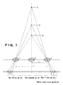
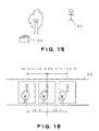
- Figure 1 illustrates the 3D photographic method.
- the figure shows the case of a triple-lens camera consisting of the lenses 1, 2 and 3, in which the arrows marked with L and L' show the spans between the observation points while X and Y show respectively the parallaxes between the principal object 5 and background 4 and the principal object 5 and foreground 6.
- the prepared negatives are projected and printed onto a photosensitive lenticular sheet, which consists of a sheet that acts as a lenticular lens and that is coated on the back side with a photosensitive material, from the side of lenticular lens in the order of photographic stations starting from one negative frame to the end of other frames.
- a part of the principal object is selected as the key-subject, and exposure is executed with positions adjusted so that the key-subject for the images in each negative are coincident. If printing is done with the photographic angle changed for each negative, the images in each negative become separated into a band pattern by the lenticular lenses, and an image band that has a width in proportion to the photographic angle is repetitively arranged in correspondence with the photographic direction.
- the image band formed on the photosensitive layer as shown in the figure is expanded sideways by the lenticular lens and will be seen as a restored image, and different restored images of the two image bands corresponding to different photographic stations will reach the left and right eye of an observer.
- a three dimensional view is obtained from the superimposition of different image information reaching the left and right eyes of the observer.
- the right eye receives the image 2 in the center while the left eye receives the image 1 on the right.
- the image band 2 covers 9° while the image bands of 1 and 3 each covers 7° of the filed of view, and the three dimensional view is obtained in the 23° viewing region in front of the 3D photograph.
- the three dimensional effect will differ depending on which photographic station corresponds to the negative, the restored images of which will reach the left and right eyes of the observer.
- the three dimensional effect will improve, but because the spacial parallax of the images that enter the left and right eyes is large, this large difference in the image information received by both eyes will be interpreted either as being out-of-focus or as a wrong vision and causes a degradation in the photographic quality.
- the printing apparatus is arranged in such a manner that the image bands seen by both of the eyes are ordinarily those that are printed at the bandwidth and band pattern at the photographic angle for which the combination of neighboring negatives have the least observation span.
- one part of the principal object, which is more important in comparison with the background and foreground objects, is specified as the key-subject, and exposure is performed so that the key-subjects of each of the frames of a negative are coincident.
- Figure 3 shows an example of a conventional 3D photograph.
- each of the frames of a negative are photographed with an appropriate spacial parallax
- the right and left eyes of a observer will catch the image bands that are not neighboring and will not be able to appreciate the appropriate spacial parallax.
- more than 4 image-bands are printed using a multiple of photographing stations from prepared negatives consisting of more than 4 frames, due to the fact that the view angle covered by a single image band is small, the right and left eyes of an observer will catch the image bands that are not neighboring depending on the observer's location, and that will result in an out-of-focus situation or a wrong vision.
- the present invention thus has the objective of realizing a 3D photographic printing method, wherein a desired spacial parallax is obtained, said photographic method producing 3D photographs of excellent three dimensional effects.
- the relationship of the positions of the foreground object, the principal object and the background object will also be different, in addition the spacial parallaxes of the foreground, principal and background objects not being fixed.
- the present invention has the objective of providing 3D photographs of excellent finish by obtaining a 3D photographic printing apparatus that takes account of the differences in the spacial parallaxes among the foreground object, the principal object and the background object.
- EP-A-0443766 discloses a method for printing 3D photographs in which a group of photographed negatives are printed as a pattern of image bands onto a photosensitive substance containing a lenticular sheet.
- the present invention provides a method of printing three dimensional (3D) photographs, wherein the image of each of a group of photographed negatives is printed as a plurality of image bands in a pattern of image bands onto a photosensitive substance mounted on a lenticular sheet, said method comprising the steps of:
- the present invention provides an apparatus for printing three dimensional (3D) photographs, wherein the image of each of a group of photographed negatives is printed as a plurality of image bands in a pattern of image bands onto a photosensitive substance mounted on a lenticular sheet, said photographic printing apparatus comprising:
- the parallax in each of the frames in the negatives which construct a 3D photograph may be measured for determining the depths of the foreground object, principal object and the background object resulting from the variation in the parallax due to the photographic location, and based on those results, an image band may be prepared which has a bandwidth and band pattern resulting in the optimum three dimensional effect for the combination of the negatives which have different observation spans.
- a negative-detecting device comprising a CCD camera and line sensors and the like may be incorporated in the printing apparatus, and with each of the negative frames inserted the spacial parallax may be determined from the specification of the coordinates on a TV monitor.
- an exposure pattern may be obtained that forms an image band having a bandwidth and band pattern resulting in a three dimensional effect from the combination of negatives of large observation spans.
- exposure may be performed at the regular bandwidth and band pattern for which the observation of 3D vision is possible for the combination of the negatives of small observation span obtained at adjoining photographic stations.
- shift in the keysubject belonging to the principal object of each of the negatives may be determined and corrected based on those results.
- a correction may be introduced so as to regulate the parallax with the background object, and after position adjustments are made the exposure is performed.
- a correction may be performed so as to regulate the parallax with the foreground object, and after position adjustments are made, exposure is performed. Even in such photographs as scenic photographs where a principal object can not be specified, the correction may be introduced by selecting an arbitrary position as the key-subject and measuring the shift.
- a negative-detecting device that consists of such items as a CCD camera and line sensors and that is incorporated into the 3D photographic printing apparatus may be used.
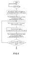
- Figures 4 and 5 show the flow chart of the program to be incorporated in the present inventive 3D photographic printing apparatus.
- the flow charts of Fig. 4 and 5 are connected together at the symbol S.
- the parallax is estimated with reference to a single point on the principal object.
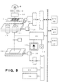
- Figure 6 shows a schematic diagram of one example of the present inventive 3D photographic printing apparatus.
- the apparatus generally consists of: an exposure section that comprises such items as a light source, a lens, an exposure station and their driving devices; an image processing section that has such functions as photographing, processing and displaying functions; and a computer for control purposes comprising a CPU, ROM and RAM; and in addition an I/O, a circuit for the purpose of executing input/ output dealings.
- the negative 7 is photographed using the CCD camera 11 and projected onto the television monitor 13 via the image processing section 12.
- the image processing section 12 transmits the coordinates specified by the cursor to a connected computer, where the shift in the image of each frame of the negative is computed and the spacial parallax determined.
- the exposure lens 15 and CCD camera 11 are mounted on an identical plate, and connected to which are the two motors 16 and 17 that move the lens and the camera in two perpendicular directions.
- the exposure station 28 also is mobile and has a motor 18 for moving the same.
- the motors 16 and 17 for moving the lens and camera and the motor 18 for the exposure station are each connected via respectively the drive circuits 19 and 20 to the control computer comprising CPU 25, ROM 26 and RAM 27.
- the keyboard 24 that is used for operating the computer and the display 23 are each connected to the computer via the I/O ports 21 and 22 in the same manner as the drive circuits 19 and 20.
- the apparatus of the present invention captures each of the frames of negatives, computes the changes in the coordinates of a reference point specified by a cursor on the screen of a television monitor, and changes the photographic angle and the printed band pattern in the event the parallax is judged to be small so that the combination of the negatives having a larger observation span is used to produce three dimensional effect.
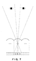
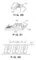
- Figure 7 shows a diagram for explaining one example of a photograph printed with the present inventive 3D photographic printing apparatus.
- the image bands of the two extremes (1) and (3) easily contain the optic angle, when viewed from the front, both eyes will receive restored images of (1) and (3), which are due to the combination of negatives of larger observation span and an excellent 3D photograph is produced.
- Figure 8 shows a diagram for explaining yet another example of a photograph printed with the present inventive 3D photographic printing apparatus.
- the restore images of the image bands (2) and (3) will reach the eyes of the observer and an excellent three dimensional photograph is obtained.
- a band pattern such as that in Fig. 3 is printed, and the restored images of the image bands (1) and (3) are made to reach the eyes of the observer to obtain an excellent 3D photograph.
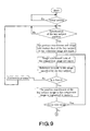
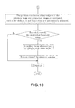
- Figures 9 and 10 show the flow chart of the program for the detection of negatives and the control of exposure station position in the present inventive 3D photographic printing apparatus.
- the symbol S in the figures indicates the fact that the flow charts are connected.
- Threshold value of the shift and the origin of the coordinate axes are specified as the initial settings, and having specified the key-subject position of the reference image the coordinates and the data at the key-subject position are input. From the comparison image, the image at the key-subject location is referenced and the coordinates of the key-subject of the comparison image obtained. By comparing the coordinates of the key-subjects of the reference image and image of comparison, the amount of shift is computed, and if the threshold value has been exceeded, a uniform value of correction is added to the each of the shifts and the exposure position recalculated. Complied with the corrected exposure position, the lens, negative and the exposure station or the like are moved, and the exposure is appropriately done.
- the decision is made to introduce a correction because, with respect to the reference image the key-subject of the comparison image is either located at a position below the initial input-setting, 17.5 mm ( namely, l 17. 5 - 18.5
- the key-subject position in each of the images does not vary and the shift is hardly existent.
- the decision is made to introduce the correction because, with respect to the reference image the key-subject position of the comparison image is located within the threshold range, 18.2 to 18.8 ( namely,
- the amount of shift is measured by specifying an arbitrary position as the key-subject. Generally, it is appropriate to specify the key-subject on the foremost object in the fore-sight out of the entire objects. In addition, it is also appropriate to fix the key-subject in advance, and in which case it is effective to place the key-subject in the central image region.
- the present inventive 3D photographic printing apparatus By utilizing the present inventive 3D photographic printing apparatus, it is possible to produce photographs with a minor focal-point blurring by means of regulating to a suitable value the spacial parallax of either the background or the foreground that results when the principal object is located more closer to foreground or to the background.
- the present invention has the advantage that, irrespective of the positions of the principal object, background object and the foreground object, excellent 3D photographs can be produced by using the present inventive 3D photographic printing apparatus, even of the likes of scenic views.
- a negative 34 inserted in the negative mask 33 is captured by a CCD camera, and the central frame of a three-frame negative is displayed as the reference image, as shown in Fig. 21, on a television monitor 35.
- the television monitor 35 is connected to an image processing section and a CPU, and by the manupulation of a track-ball 38 and the cursor 37 can be moved.
- the position of a key-subject 36 on the screen is specified by the cursor 37.
- the coordinates and the image of the key-subject specified are captured, and based on the captured image information the CCD camera scans and determines the key-subjects on the comparison images.
- the distances between the key-subjects of the comparison images and that of the reference image are obtained, and an amount of correction is determined with reference to a threshold value that is preset.
Landscapes
- Physics & Mathematics (AREA)
- General Physics & Mathematics (AREA)
- Stereoscopic And Panoramic Photography (AREA)
- Cameras Adapted For Combination With Other Photographic Or Optical Apparatuses (AREA)
Claims (4)
- Procédé de tirage de photographies tridimensionnelles, dans lequel l'image de chacun d'un groupe de négatifs photographiés est tirée sous la forme d'une pluralité de bandes d'image suivant un motif de bandes d'image sur une substance photosensible montée sur une feuille lenticulaire, ledit procédé comprenant les étapes consistant à:mesurer la parallaxe spatiale (X, Y) entre des points de référence correspondants sur les images dudit groupe de négatifs;tirer, sous la forme d'une pluralité de bandes d'image, l'image de chacun desdits négatifs, suivant un motif dont un observateur peut voir à travers la feuille lenticulaire cette combinaison des images correspondant aux négatifs obtenus à partir de points d'observation séparés d'une portée d'observation supérieure à une portée d'observation minimale prédéterminée (L) si la valeur de ladite parallaxe spatiale des images de ladite combinaison est inférieure à une valeur prédéterminée; ettirer, sous la forme d'une pluralité de bandes d'image, les images de chacun desdits négatifs, suivant un motif dont un observateur peut voir à travers la feuille lenticulaire cette combinaison des images correspondant aux négatifs obtenus à partir de points d'observation séparés de la portée d'observation minimale prédéterminée (L) si la valeur de ladite parallaxe spatiale des images de ladite combinaison dépasse la valeur prédéterminée.
- Procédé selon la revendication 1, caractérisé en ce qu'il comprend en outre les étapes consistant à:utiliser un dispositif de détection de négatif pour former une image de chaque négatif, le décalage de position d'un sujet clé entre chaque image et une image de référence étant mesuré pour une multiplicité de négatifs qui constituent les substances de base nécessaires à la composition d'une seule photographie tridimensionnelle, le sujet clé étant déterminé sur un objet principal à photographier;comparer le décalage de position d'un sujet clé pour chaque image à une valeur de seuil prédéterminée;introduire une correction des positions des bandes d'image tirées pour réguler la parallaxe spatiale d'un objet d'arrière-plan dans le cas où le décalage de position dudit sujet clé sur l'objet principal dépasse la valeur de seuil; etintroduire une correction des positions des bandes d'image tirées pour réguler la parallaxe spatiale d'un objet de premier plan dans le cas où le décalage de position du sujet clé sur l'objet principal est inférieur à la valeur de seuil.
- Appareil de tirage de photographies tridimensionnelles, dans lequel l'image de chacun d'un groupe de négatifs photographiés est tirée sous la forme d'une pluralité de bandes d'image suivant un motif de bandes d'image sur une substance photosensible montée sur une feuille lenticulaire, ledit appareil de tirage photographique comprenant:une caméra vidéo pour former les images dudit groupe de négatifs;un moyen pour mesurer la parallaxe spatiale entre des points de référence correspondants sur les images formées par ladite caméra vidéo;un moyen pour sélectionner les négatifs obtenus à partir de points d'observation séparés d'une portée d'observation minimale prédéterminée (L) si la parallaxe spatiale mesurée dépasse une valeur prédéterminée, et pour sélectionner les négatifs obtenus à partir de points d'observation séparés d'une portée d'observation supérieure à la portée d'observation minimale prédéterminée (L) si la parallaxe spatiale mesurée est inférieure à la valeur prédéterminée; etun moyen pour tirer les négatifs sélectionnés suivant un motif de bandes d'image sur le substrat photosensible monté sur la feuille lenticulaire.
- Appareil selon la revendication 3, caractérisé en ce qu'il comprend en outre:un moyen pour mesurer le décalage de position d'un sujet clé sur l'objet principal entre l'image de chaque négatif et une image de référence;un moyen pour comparer le décalage de position dudit sujet clé sur l'objet principal pour chaque image à une valeur de seuil; etun moyen pour introduire une correction des positions des bandes d'image tirées de façon à réguler, sur la base des résultats dudit moyen de comparaison, la parallaxe spatiale d'un objet d'arrière-plan ou d'un objet de premier plan.
Applications Claiming Priority (7)
| Application Number | Priority Date | Filing Date | Title |
|---|---|---|---|
| JP195974/92 | 1992-06-30 | ||
| JP19597492A JP2689825B2 (ja) | 1992-06-30 | 1992-06-30 | 3d立体写真の焼付方法および装置 |
| JP19597492 | 1992-06-30 | ||
| JP19920992 | 1992-07-02 | ||
| JP19920992A JP2725533B2 (ja) | 1992-07-02 | 1992-07-02 | 3d立体写真焼付方法および装置 |
| JP199209/92 | 1992-07-02 | ||
| PCT/JP1993/000890 WO1994000798A1 (fr) | 1992-06-30 | 1993-06-29 | Procede et equipement d'impression stereographique en trois dimensions |
Publications (3)
| Publication Number | Publication Date |
|---|---|
| EP0601208A1 EP0601208A1 (fr) | 1994-06-15 |
| EP0601208A4 EP0601208A4 (fr) | 1994-12-14 |
| EP0601208B1 true EP0601208B1 (fr) | 2001-11-28 |
Family
ID=26509448
Family Applications (1)
| Application Number | Title | Priority Date | Filing Date |
|---|---|---|---|
| EP93913603A Expired - Lifetime EP0601208B1 (fr) | 1992-06-30 | 1993-06-29 | Procede et equipement d'impression stereographique en trois dimensions |
Country Status (7)
| Country | Link |
|---|---|
| US (1) | US5500712A (fr) |
| EP (1) | EP0601208B1 (fr) |
| KR (1) | KR0158937B1 (fr) |
| CN (1) | CN1055162C (fr) |
| CA (1) | CA2116554C (fr) |
| DE (1) | DE69331218T2 (fr) |
| WO (1) | WO1994000798A1 (fr) |
Families Citing this family (9)
| Publication number | Priority date | Publication date | Assignee | Title |
|---|---|---|---|---|
| US5488451A (en) * | 1994-05-03 | 1996-01-30 | National Graphics, Inc. | Method of producing multidimensional lithographic separations free of moire interference |
| US5600402A (en) * | 1995-05-04 | 1997-02-04 | Kainen; Daniel B. | Method and apparatus for producing three-dimensional graphic images using a lenticular sheet |
| US5967032A (en) * | 1998-05-21 | 1999-10-19 | Lti Corporation | Printing process using a thin sheet lenticular lens material |
| US6490092B1 (en) | 2000-03-27 | 2002-12-03 | National Graphics, Inc. | Multidimensional imaging on a curved surface using lenticular lenses |
| CN101464621B (zh) * | 2008-12-17 | 2010-12-08 | 顾金昌 | 一种立体数码拼图成像镜头移动装置及其方法 |
| US8136938B2 (en) * | 2009-05-19 | 2012-03-20 | William Karszes | System and method for printing on lenticular sheets |
| JP5695395B2 (ja) * | 2010-11-19 | 2015-04-01 | インターナショナル・ビジネス・マシーンズ・コーポレーションInternational Business Machines Corporation | 立体画像生成方法及びその装置 |
| CN103576426A (zh) * | 2012-08-08 | 2014-02-12 | 西蒙·R·杰马耶勒 | 在胶片上预曝光立体图像的方法 |
| CN103576438B (zh) * | 2012-08-08 | 2017-03-01 | 西蒙·R·杰马耶勒 | 制作三维照片的方法 |
Citations (1)
| Publication number | Priority date | Publication date | Assignee | Title |
|---|---|---|---|---|
| EP0443766A2 (fr) * | 1990-02-20 | 1991-08-28 | Lentec Corporation | Imprimante 3D à deux stades |
Family Cites Families (10)
| Publication number | Priority date | Publication date | Assignee | Title |
|---|---|---|---|---|
| US3895867A (en) * | 1971-08-12 | 1975-07-22 | Dimensional Dev Corp | Three dimensional pictures and method of composing them |
| US3960563A (en) * | 1973-09-20 | 1976-06-01 | Dimensional Development Corporation | Methods and apparatus for taking and composing stereoscopic pictures |
| US3953869A (en) * | 1974-09-24 | 1976-04-27 | Dimensional Development Corporation | Stereoscopic photography apparatus |
| US4101210A (en) * | 1976-06-21 | 1978-07-18 | Dimensional Development Corporation | Projection apparatus for stereoscopic pictures |
| JPS587981A (ja) * | 1981-07-07 | 1983-01-17 | Hitachi Denshi Ltd | テレビジヨン・カメラの調整値表示方法 |
| US4650282A (en) * | 1985-12-16 | 1987-03-17 | Lo Allen K W | Visual parallax compensation 3-D image structure |
| US4852972A (en) * | 1987-06-08 | 1989-08-01 | Wah Lo Allen K | Method of controlling variation of density of images in 3-D pictures |
| US4800407A (en) * | 1988-02-01 | 1989-01-24 | Wah Lo Allen K | Total focus 3-D camera and 3-D image structure |
| US4903069A (en) * | 1989-02-24 | 1990-02-20 | Image Technology, Inc. | Automatic three-dimensional photo printer to align the key subject image |
| US5111236A (en) * | 1990-03-27 | 1992-05-05 | Lo Allen K W | Multiple-print 3-D printer and process |
-
1993
- 1993-06-29 KR KR1019940700572A patent/KR0158937B1/ko not_active IP Right Cessation
- 1993-06-29 US US08/199,222 patent/US5500712A/en not_active Expired - Fee Related
- 1993-06-29 CA CA002116554A patent/CA2116554C/fr not_active Expired - Fee Related
- 1993-06-29 WO PCT/JP1993/000890 patent/WO1994000798A1/fr active IP Right Grant
- 1993-06-29 CN CN93107975A patent/CN1055162C/zh not_active Expired - Fee Related
- 1993-06-29 EP EP93913603A patent/EP0601208B1/fr not_active Expired - Lifetime
- 1993-06-29 DE DE69331218T patent/DE69331218T2/de not_active Expired - Fee Related
Patent Citations (1)
| Publication number | Priority date | Publication date | Assignee | Title |
|---|---|---|---|---|
| EP0443766A2 (fr) * | 1990-02-20 | 1991-08-28 | Lentec Corporation | Imprimante 3D à deux stades |
Also Published As
| Publication number | Publication date |
|---|---|
| KR0158937B1 (ko) | 1999-03-30 |
| US5500712A (en) | 1996-03-19 |
| EP0601208A4 (fr) | 1994-12-14 |
| DE69331218D1 (de) | 2002-01-10 |
| CN1055162C (zh) | 2000-08-02 |
| CA2116554C (fr) | 1997-04-15 |
| CA2116554A1 (fr) | 1994-01-06 |
| DE69331218T2 (de) | 2002-06-27 |
| WO1994000798A1 (fr) | 1994-01-06 |
| CN1081768A (zh) | 1994-02-09 |
| EP0601208A1 (fr) | 1994-06-15 |
Similar Documents
| Publication | Publication Date | Title |
|---|---|---|
| EP1085769B1 (fr) | Dispositif de prise d'images stéréoscopiques | |
| US8928755B2 (en) | Information processing apparatus and method | |
| US4650282A (en) | Visual parallax compensation 3-D image structure | |
| US6483644B1 (en) | Integral image, method and device | |
| EP0327303B1 (fr) | Caméra 3-D à profondeur de champ plus élevée et structure d'image 3-D | |
| JPH06194758A (ja) | 奥行画像形成方法及び装置 | |
| GB2354391A (en) | 3D camera having maximum parallax warning. | |
| US5337096A (en) | Method for generating three-dimensional spatial images | |
| EP0601208B1 (fr) | Procede et equipement d'impression stereographique en trois dimensions | |
| EP0673517B1 (fr) | Appareil photo a double mode, tridimensionnel (3-d) et bidimensionnel (2-d) avec chicanes amovibles | |
| US5905593A (en) | Method and apparatus of producing 3D video by correcting the effects of video monitor on lenticular layer | |
| Lincoln et al. | Multi-view lenticular display for group teleconferencing | |
| EP1310106A1 (fr) | Procede et systeme de revision d'image tridimensionnelle | |
| KR100786861B1 (ko) | 입체 영상 디스플레이 장치 | |
| US5465128A (en) | 2-D and 3-D multi-lens camera with one lens having a wider plane than the other lenses | |
| US6366407B2 (en) | Lenticular image product with zoom image effect | |
| JPH0749466A (ja) | 画像表示方法 | |
| JP2689825B2 (ja) | 3d立体写真の焼付方法および装置 | |
| JP3059962B1 (ja) | 眼鏡無し立体映像表示装置 | |
| EP0009065B1 (fr) | Procédé pour la prise de vue d'une photographie stéréoscopique | |
| JP2007288229A (ja) | 画像撮影装置 | |
| US3522046A (en) | Three-dimensional color pictures and method of making | |
| CN100437350C (zh) | 立体照片景深计算公式和立体摄影景深定位尺 | |
| JP2002330451A (ja) | 立体映像表示装置における頭部位置検出装置の設定方法および頭部位置検出装置 | |
| JPH08180206A (ja) | 画像の立体表示方法 |
Legal Events
| Date | Code | Title | Description |
|---|---|---|---|
| PUAI | Public reference made under article 153(3) epc to a published international application that has entered the european phase |
Free format text: ORIGINAL CODE: 0009012 |
|
| 17P | Request for examination filed |
Effective date: 19940301 |
|
| AK | Designated contracting states |
Kind code of ref document: A1 Designated state(s): DE FR GB |
|
| RHK1 | Main classification (correction) |
Ipc: G03B 35/00 |
|
| A4 | Supplementary search report drawn up and despatched |
Effective date: 19941024 |
|
| AK | Designated contracting states |
Kind code of ref document: A4 Designated state(s): CH DE FR GB IT |
|
| 17Q | First examination report despatched |
Effective date: 19961104 |
|
| RBV | Designated contracting states (corrected) |
Designated state(s): CH DE FR GB IT LI |
|
| GRAG | Despatch of communication of intention to grant |
Free format text: ORIGINAL CODE: EPIDOS AGRA |
|
| GRAG | Despatch of communication of intention to grant |
Free format text: ORIGINAL CODE: EPIDOS AGRA |
|
| GRAH | Despatch of communication of intention to grant a patent |
Free format text: ORIGINAL CODE: EPIDOS IGRA |
|
| RBV | Designated contracting states (corrected) |
Designated state(s): DE FR GB |
|
| GRAH | Despatch of communication of intention to grant a patent |
Free format text: ORIGINAL CODE: EPIDOS IGRA |
|
| GRAA | (expected) grant |
Free format text: ORIGINAL CODE: 0009210 |
|
| AK | Designated contracting states |
Kind code of ref document: B1 Designated state(s): DE FR GB |
|
| REG | Reference to a national code |
Ref country code: GB Ref legal event code: IF02 |
|
| REF | Corresponds to: |
Ref document number: 69331218 Country of ref document: DE Date of ref document: 20020110 |
|
| ET | Fr: translation filed | ||
| PGFP | Annual fee paid to national office [announced via postgrant information from national office to epo] |
Ref country code: FR Payment date: 20020610 Year of fee payment: 10 |
|
| PGFP | Annual fee paid to national office [announced via postgrant information from national office to epo] |
Ref country code: GB Payment date: 20020626 Year of fee payment: 10 |
|
| PGFP | Annual fee paid to national office [announced via postgrant information from national office to epo] |
Ref country code: DE Payment date: 20020702 Year of fee payment: 10 |
|
| PLBE | No opposition filed within time limit |
Free format text: ORIGINAL CODE: 0009261 |
|
| STAA | Information on the status of an ep patent application or granted ep patent |
Free format text: STATUS: NO OPPOSITION FILED WITHIN TIME LIMIT |
|
| 26N | No opposition filed | ||
| PG25 | Lapsed in a contracting state [announced via postgrant information from national office to epo] |
Ref country code: GB Free format text: LAPSE BECAUSE OF NON-PAYMENT OF DUE FEES Effective date: 20030629 |
|
| PG25 | Lapsed in a contracting state [announced via postgrant information from national office to epo] |
Ref country code: DE Free format text: LAPSE BECAUSE OF NON-PAYMENT OF DUE FEES Effective date: 20040101 |
|
| GBPC | Gb: european patent ceased through non-payment of renewal fee |
Effective date: 20030629 |
|
| PG25 | Lapsed in a contracting state [announced via postgrant information from national office to epo] |
Ref country code: FR Free format text: LAPSE BECAUSE OF NON-PAYMENT OF DUE FEES Effective date: 20040227 |
|
| REG | Reference to a national code |
Ref country code: FR Ref legal event code: ST |