EP0601202B1 - Light transmittable members, and method of adjusting natural lighting quantity and natural lighting range by use of the light transmittable members - Google Patents
Light transmittable members, and method of adjusting natural lighting quantity and natural lighting range by use of the light transmittable members Download PDFInfo
- Publication number
- EP0601202B1 EP0601202B1 EP93913527A EP93913527A EP0601202B1 EP 0601202 B1 EP0601202 B1 EP 0601202B1 EP 93913527 A EP93913527 A EP 93913527A EP 93913527 A EP93913527 A EP 93913527A EP 0601202 B1 EP0601202 B1 EP 0601202B1
- Authority
- EP
- European Patent Office
- Prior art keywords
- natural lighting
- light transmittable
- light
- columns
- refractive columns
- Prior art date
- Legal status (The legal status is an assumption and is not a legal conclusion. Google has not performed a legal analysis and makes no representation as to the accuracy of the status listed.)
- Expired - Lifetime
Links
Images




Classifications
-
- E—FIXED CONSTRUCTIONS
- E06—DOORS, WINDOWS, SHUTTERS, OR ROLLER BLINDS IN GENERAL; LADDERS
- E06B—FIXED OR MOVABLE CLOSURES FOR OPENINGS IN BUILDINGS, VEHICLES, FENCES OR LIKE ENCLOSURES IN GENERAL, e.g. DOORS, WINDOWS, BLINDS, GATES
- E06B9/00—Screening or protective devices for wall or similar openings, with or without operating or securing mechanisms; Closures of similar construction
- E06B9/24—Screens or other constructions affording protection against light, especially against sunshine; Similar screens for privacy or appearance; Slat blinds
-
- E—FIXED CONSTRUCTIONS
- E06—DOORS, WINDOWS, SHUTTERS, OR ROLLER BLINDS IN GENERAL; LADDERS
- E06B—FIXED OR MOVABLE CLOSURES FOR OPENINGS IN BUILDINGS, VEHICLES, FENCES OR LIKE ENCLOSURES IN GENERAL, e.g. DOORS, WINDOWS, BLINDS, GATES
- E06B9/00—Screening or protective devices for wall or similar openings, with or without operating or securing mechanisms; Closures of similar construction
- E06B9/24—Screens or other constructions affording protection against light, especially against sunshine; Similar screens for privacy or appearance; Slat blinds
- E06B2009/2417—Light path control; means to control reflection
-
- F—MECHANICAL ENGINEERING; LIGHTING; HEATING; WEAPONS; BLASTING
- F21—LIGHTING
- F21S—NON-PORTABLE LIGHTING DEVICES; SYSTEMS THEREOF; VEHICLE LIGHTING DEVICES SPECIALLY ADAPTED FOR VEHICLE EXTERIORS
- F21S11/00—Non-electric lighting devices or systems using daylight
Definitions
- the present invention relates to light transmissive panels used as lighting windows in the openings of ceilings, floors, walls, etc. of general buildings.
- the present invention relates to light transmissive panels to be stationarily installed in the openings for optically changing the sunlight incident on the openings by way of refraction, reflection, etc. for obtaining desired natural lighting by selectively adjusting the quantity and range of the sunlight changing in relation with the annual and daily motion of the sun, thereby controlling the quantity of heat in the indoor space.
- Most of the openings in the ceilings, walls, etc. or general buildings are provided respectively as a lighting window using a single glass sheet, a double layer glass panel with an air layer between two glass sheets or a glass panel with a laminated resin layer, etc., for interior lighting using solar light or artificial illumination, etc.
- Special lighting windows intended for intercepting direct sunlight are disclosed in West German Patent Laid-Open Nos. 1683284, 1906990, 3138262, 3227118, etc.
- These lighting windows are shading devices using an improved Fresnel prism system which is a plate with many right-angled prisms with a metallic film on some optical faces integrally formed as plural blocks.
- West German Patent Laid-open Nos is a plate with many right-angled prisms with a metallic film on some optical faces integrally formed as plural blocks.
- 3138262 and 3227118 disclose an improved technique for introducing scattered light, to perfectly intercept direct sunlight and to secure indoor illumination.
- a lighting window using a Fresnel prism system does not contribute to securing a comfortable temperature range in an indoor dwelling space. The reason is that since the quality of heat obtained from sunlight depends on the annual and daily motion of the sun, i.e., changes due to seasons and daily time zones, intercepting all the sunlight means that a sufficient warming effect cannot be obtained in winter when a larger quantity of heat is required.
- the present invention provides a light transmissive panel as defined in claim 1.
- the light transmissive panel according to the present invention has reflective columns located between two transmissive plates, with holders located at the ends of the plates on both sides. Therefore, incident light can be optically changed by way of reaction, reflection, etc. without impairing the optical function at about the centers of the bodies of the refractive columns. Furthermore, the holders are advantageous for changing the arrangement of the refractive columns, and prevents movement, play, deflection, etc. Furthermore, if clearances are formed between the holders and the sealed edges of the plates, the thermal expansion and contraction of the refractive columns in the axial direction can be accommodated, and the refractive columns can be fastened always in stable state.
- the present invention can adjust the difference in the quantity of heat in the interior caused by sunlight patterns of respective seasons or respective time zones due to the annual motion or daily motion of the sun, by using, the lighting quantity or range adjusting methods described below to adjust in reference to the difference in the altitude or azimuth of the sun.
- the present invention is epochal and very significant, since the light transmissive panel stationarily installed can be used without any adjustment, to positively intercept the summer sunlight large in the quantity of heat for preventing the temperature rise in the interior for contribution to energy saving in synergism with the heat insulation effect of the multi-layer panel, and to partially or positively introduce the vernal and autumnal or winter sunlight relatively small in the quantity of heat for effectively utilizing the heat.
- the light transmissive panels of the present invention stated in the respective claims are formed as multi-layer panels excellent in heat insulation, sound insulation, etc. with an air layer between two glass sheets of float plate glass or figured glass or two transmissive resin sheets, etc., as shown in Figs. 1 to 12.
- the light transmissive panels of the present invention can be effectively applied not only as lighting windows in the openings of the ceilings, floors, walls, etc. of general buildings but also as front panels such as illumination-installed decorative walls of general buildings.
- a frame, etc. made of a metal, etc. is installed in the opening, for installing the light transmissive panel in it.
- Figs. 1 to 6 are schematic illustrations for illustrating the light transmissive panel 1 stated in claim 1.
- the light transmissive panel 1 stated in claim 1 consists of two transmissive plates 1a and 1b and plural refractive columns located in parallel to each other between the plates 1a and 1b, as shown in Figs. 1 to 6 and the respective refractive columns 2 are fastened between the plates 1a and 1b by holders 3 supporting the respective refractive columns 2, with the short portions at the ends of the bodies of the refractive columns 2 on both sides as supported faces, as shown in the schematic front view of Fig. 2.
- the refractive columns 2 are columns produced by extrusion molding of a synthetic resin such as acrylic resin or polycarbonate or molded glass columns, and those illustrated in Figs. 1 to 6 are right-angled triangles in sectional form.
- the holders 3 are made of an elastic synthetic resin such as rubber or the same hard synthetic resin as used for the refractive columns 2, or metallic parts such as leaf springs, or seals with flexibility when hardened between the two plates 1a and 1b and the respective refractive columns 2 or made by combining these materials.
- the holders in Figs. 1 to 6 are located at the ends of the respective refractive columns 2 on both sides, as shown in the schematic front view of Fig. 2. Therefore, if the light transmissive panel 1 of the present invention is installed in an opening of a building, the sunlight, etc. incident on one of the plates, 1a, is optically changed by way or refraction, reflection, etc., depending on the incident angle, almost in the entire range of the bodies of the refractive columns 2, and the optically changed light is transmitted through the other plate 1b into the interior.
- the holders 3 located at the ends on both sides can be hidden under a metallic frame to allow excellent designing.
- the quantity of heat is accumulated in the refractive columns 2, depending on the change in the quantity of heat contained in the sunlight, and the refractive columns 2 may be thermally expanded or deflected. This inconvenience can be met by the fixing mechanisms for the refractive columns 2 shown in Figs. 3 and 4.
- a fixing mechanism to meet the thermal expansion or contraction of the refractive columns 2 in the axial direction is shown in the schematic front view of Fig. 3.
- the holders 3 are located at the ends of the refractive columns 2 on both sides, as in Fig. 2, and in this case, a clearance 4 is formed between the ends of the refractive columns 2 at least on one side and the seal 1d provided at the periphery of the plates 1a and 1b.
- the existence of the clearance 4 prevents that when the refractive columns 2 are thermally expanded in the axial direction, the ends of the refractive columns 2 contact the sealed 1d, for deforming the seal 1d and the refractive columns 2 by the stress.
- the holders 3 slightly more narrow than the distance between the plates 1a and 1b achieved by the seal 1d are strongly and integrally set with the ends of the refractive columns 2, so that when the refractive columns 2 are expanded in the axial direction, the holders 3 may be moved in the clearance 4 in the axial direction.
- FIG. 4 Another fixing mechanism for preventing the refractive columns 2 from being deflected in their bodies by their own weight or heat is illustrated in the schematic front view of Fig. 4.
- a third holder 3 is installed also at the centers of the refractive columns 2, for preventing the deflection at the centers of the bodies where stresses are concentrated.
- the third holder 3 is installed almost as a straight line in the direction perpendicular to the refractive columns 2, the light transmissive panel appears like a latticework in combination with the holders at the ends on both sides, or the frame hiding the holders 3 at the ends on both sides.
- Fig. 5 is a schematic illustration showing the structure of the holder 3 as an example.
- a member of the holder 3 of this example is almost a rectangle with a width almost equal to the distance between the plates 1a and 1b and with a proper length to accommodate a proper number of the refractive columns 2, as illustrated, and has column fitting portions 3a almost the same in sectional form as the ends or bodies of the respective columns 2. If the successive refractive columns 2 are the same in form as illustrated, the successive column fitting portions 3a are the same in form, but if the refractive columns 2 are respectively different in form, the column fitting portions must be formed to correspond to the respectively differently formed refractive columns 2, needless to say.
- the column fitting portions 3a are grooves or through holes, etc.
- the column fitting portions 3a formed as grooves are used to hold the refractive columns 2 at the ends on both sides, and the column fitting portions 3a formed as through holes are used to hold the refractive columns 2 at the centers.
- the number of the holders 3 is properly decided, considering the size, etc. of the plates 1a and 1b of the light transmissive panel 1, depending on working efficiency, productivity, etc.
- Each member of the holder 3 has a connecting recess 3b and a connecting protrusion 3b at both the ends in the longitudinal direction.
- a proper number of the members of the holder 3 are connected through the connecting recesses and protrusions 3b, to form the holder 3, and the refractive columns 2 are inserted at their ends on both sides or at their ends on both sides and at their centers into the column fitting portions 3a of the holders 3. Then, the respective refractive columns 2 are located between the two plates 1a and 1b.
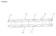
- the holder 3 of Fig. 6 can be used for the refractive columns 3 trapezoidal in sectional form, and consists of a first half 3A and a second half 3B formed by splitting the holder 3 at the center in the longitudinal direction.
- the holder 3 of this structure can be advantageously used for holding the refractive columns 2 at the centers of their bodies.
- a proper number of the refractive columns 2 can be assembled with a set of members of the holder 3, for forming a unit which can then be connected with other similarly assembled units through the connecting recesses and protrusions 3b, for greatly simplifying the assembling work.
- the refractive columns 2 illustrated in Fig. 7 are right-angled prisms allowing total reflection which can be preferably used for the lighting quantity adjusting method of the present invention.
- Fig. 7 shows a structure in which the light transmissive panel 1 is installed obliquely in a skylight.
- the bottom faces opposite to the apexes of the refractive columns 2 are kept in contact with the plate 1a of the light transmissive panel 1.
- These refractive columns 2 are located in order that the sunlight at the culmination altitude in summer, i.e., the sunlight pattern S3 with an incident angle of y against the horizontal plane may be perpendicular to the bottom faces opposite to the apexes of the refractive columns 2.
- the winter sunlight pattern S1 with an incident angle of ⁇ against the horizontal plane is positively introduced into the interior as retracted light X1
- the vernal and autumnal sunlight pattern S with an incident angle of ⁇ against the horizontal plane H is partially intercepted as reflected light Y2 while the balance is introduced as refracted light X2.
- Figs. 8 and 9 have a light control section 6 composed of various members attached to the plate 1b installed on the interior side.
- the light transmissive panel of Fig. 8 has a lattice louvre or honeycomb louvre with metallic reflecting faces made of aluminum, etc. as the reflected light control members constituting the light control section 6. If the light transmissive panel 1 is used as a lighting window at a ceiling, etc., the sunlight pattern S1 transmitted through the refractive columns 2 is reflected by the light control members 6, being turned into interior light T1 progressing in the direction almost perpendicular to the plate 1b of the light transmissive panel 1, for creating a soft atmosphere in the interior space.
- the reflected light control members constituting the light control section 6 can be provided at a proper angle by a proper means. In this example, they are provided in the direction perpendicular to the plate 1b, being held between the plate 1b and a plate 1c.
- the light transmissive panel 1 of Fig. 9 uses a glass sheet as the plate 1b installed on the interior side, and the plate 1b has fine undulations formed on the surface, to constitute the light control section 6 with a nonreflecting surface. If the light transmissive panel 1 is used as a lighting window at a ceiling, etc., the sunlight pattern S1 transmitted through the refractive columns 2 is scattered by the light control section 6 into interior light T1, to create a soft atmosphere in the interior space like the light transmissive panel 1 of Fig. 8.
- the sunlight pattern S1 incident on the light transmitting panel 1 is somewhat changed in incident angle and transmitted through the refractive columns.
- the same effect as achieved when the light control section 6 is provided for the plate 1b can be achieved, and in addition, since the reflected light from the surface is divided, a soft decorative effect can be achieved.
- the light control section 6 in the example of Fig. 9 can also be provided on the refractive columns side of the plate 1a or 1b.
- the example of Fig. 10 has reflectors 7a formed by a vapor-deposited film of a metal such as aluminium on the optical faces of the refractive columns 2.
- the reflectors 7a make the sunlight pattern S3 with a certain incident angle reflected as reflected light Y3 by total reflection, to prevent the summer sunlight from going into the interior, and on the other hand, the winter sunlight pattern S1 and the vernal and autumnal sunlight pattern S2 are introduced as refractive light X1 and X2 respectively.
- the example of Fig 11 has absorbers 7b formed on the optical faces of the refractive columns 2 for preventing the reflection of the sunlight pattern S3 with a certain incident angle.
- the absorbers 7b can be provided, for example, by forming a thin calcium fluoride film by vapor deposition onto the optical faces of the refractive columns 2. Since the absorbers 7b absorb the sunlight pattern S3 with a certain incident angle, the summer sunlight pattern S3 can be intercepted, and on the other hand, the winter sunlight pattern S1 and the vernal and autumnal sunlight pattern S2 can be introduced as refracted light X1 and X2 respectively.
- the example of Fig. 12 has the pressure in the air layer reduced from a suction port, etc. formed in the seal 1d. Under reduced pressure, the air in the air layer is lowered in overall heat transfer coefficient, to enhance the heat insulation effect of the light transmitting panel 1.
- the plates 1a and 1b are effectively prevented from being deformed by the reduced pressure, thanks to the seal 1d and the holders 3 provided at the edges, and if the light transmitting panel 1 is large in area, also thanks to the holder 3 and the refractive columns 2 provided at intermediate portions.
Landscapes
- Engineering & Computer Science (AREA)
- Structural Engineering (AREA)
- Architecture (AREA)
- Civil Engineering (AREA)
- Optical Elements Other Than Lenses (AREA)
- Building Environments (AREA)
- Non-Portable Lighting Devices Or Systems Thereof (AREA)
- Electrochromic Elements, Electrophoresis, Or Variable Reflection Or Absorption Elements (AREA)
- Display Devices Of Pinball Game Machines (AREA)
- Blinds (AREA)
Abstract
Description
- The present invention relates to light transmissive panels used as lighting windows in the openings of ceilings, floors, walls, etc. of general buildings. In more detail, the present invention relates to light transmissive panels to be stationarily installed in the openings for optically changing the sunlight incident on the openings by way of refraction, reflection, etc. for obtaining desired natural lighting by selectively adjusting the quantity and range of the sunlight changing in relation with the annual and daily motion of the sun, thereby controlling the quantity of heat in the indoor space.
- Most of the openings in the ceilings, walls, etc. or general buildings are provided respectively as a lighting window using a single glass sheet, a double layer glass panel with an air layer between two glass sheets or a glass panel with a laminated resin layer, etc., for interior lighting using solar light or artificial illumination, etc. Special lighting windows intended for intercepting direct sunlight are disclosed in West German Patent Laid-Open Nos. 1683284, 1906990, 3138262, 3227118, etc. These lighting windows are shading devices using an improved Fresnel prism system which is a plate with many right-angled prisms with a metallic film on some optical faces integrally formed as plural blocks. Especially West German Patent Laid-open Nos. 3138262 and 3227118 disclose an improved technique for introducing scattered light, to perfectly intercept direct sunlight and to secure indoor illumination. However, such a lighting window using a Fresnel prism system does not contribute to securing a comfortable temperature range in an indoor dwelling space. The reason is that since the quality of heat obtained from sunlight depends on the annual and daily motion of the sun, i.e., changes due to seasons and daily time zones, intercepting all the sunlight means that a sufficient warming effect cannot be obtained in winter when a larger quantity of heat is required.
- The present invention provides a light transmissive panel as defined in
claim 1. - The light transmissive panel according to the present invention has reflective columns located between two transmissive plates, with holders located at the ends of the plates on both sides. Therefore, incident light can be optically changed by way of reaction, reflection, etc. without impairing the optical function at about the centers of the bodies of the refractive columns. Furthermore, the holders are advantageous for changing the arrangement of the refractive columns, and prevents movement, play, deflection, etc. Furthermore, if clearances are formed between the holders and the sealed edges of the plates, the thermal expansion and contraction of the refractive columns in the axial direction can be accommodated, and the refractive columns can be fastened always in stable state.
- In general, the present invention can adjust the difference in the quantity of heat in the interior caused by sunlight patterns of respective seasons or respective time zones due to the annual motion or daily motion of the sun, by using, the lighting quantity or range adjusting methods described below to adjust in reference to the difference in the altitude or azimuth of the sun. Thus, the present invention is epochal and very significant, since the light transmissive panel stationarily installed can be used without any adjustment, to positively intercept the summer sunlight large in the quantity of heat for preventing the temperature rise in the interior for contribution to energy saving in synergism with the heat insulation effect of the multi-layer panel, and to partially or positively introduce the vernal and autumnal or winter sunlight relatively small in the quantity of heat for effectively utilizing the heat.
- Preferred embodiments of the invention will now be described with reference to the attached figures in which:
- Fig. 1 is a schematic sectional view showing the
light transmissive panel stated in
claim 1. - Fig. 2 through 4 are schematic front views showing
the light transmissive panel stated in
claim 1. - Figs. 5 and 6 are schematic illustrations showing the
holders used in the light transmissive panel stated in
claim 1. - Figs. 5 & 6 are schematic illustrations showing the
holders used in the light transmissive panel stated in
claim 1. - Fig. 7 is a functional illustration showing a light quantity adjusting method.
- Figs. 8 to 12 are schematic illustrations showing other examples of the light.
-
- The light transmissive panels of the present invention stated in the respective claims are formed as multi-layer panels excellent in heat insulation, sound insulation, etc. with an air layer between two glass sheets of float plate glass or figured glass or two transmissive resin sheets, etc., as shown in Figs. 1 to 12.
- The light transmissive panels of the present invention can be effectively applied not only as lighting windows in the openings of the ceilings, floors, walls, etc. of general buildings but also as front panels such as illumination-installed decorative walls of general buildings. To install a light transmissive panel in an opening of a general building, a frame, etc. made of a metal, etc. is installed in the opening, for installing the light transmissive panel in it.
- Figs. 1 to 6 are schematic illustrations for illustrating the light
transmissive panel 1 stated inclaim 1. The lighttransmissive panel 1 stated inclaim 1 consists of two transmissive plates 1a and 1b and plural refractive columns located in parallel to each other between the plates 1a and 1b, as shown in Figs. 1 to 6 and the respectiverefractive columns 2 are fastened between the plates 1a and 1b byholders 3 supporting the respectiverefractive columns 2, with the short portions at the ends of the bodies of therefractive columns 2 on both sides as supported faces, as shown in the schematic front view of Fig. 2. - The
refractive columns 2 are columns produced by extrusion molding of a synthetic resin such as acrylic resin or polycarbonate or molded glass columns, and those illustrated in Figs. 1 to 6 are right-angled triangles in sectional form. Theholders 3 are made of an elastic synthetic resin such as rubber or the same hard synthetic resin as used for therefractive columns 2, or metallic parts such as leaf springs, or seals with flexibility when hardened between the two plates 1a and 1b and the respectiverefractive columns 2 or made by combining these materials. In the example shown in Fig. 1, the flat optical faces of therefractive columns 2 contact one of the plates, 1a, and theholders 3 are formed to have column fitting portions to fit the apex angles of therefractive columns 2 and inserted between therefractive columns 2 at the ends of their bodies on both sides and the plate 1b, for fastening therefractive columns 2 between the two plates 1a and 1b. - The holders in Figs. 1 to 6 are located at the ends of the respective
refractive columns 2 on both sides, as shown in the schematic front view of Fig. 2. Therefore, if the lighttransmissive panel 1 of the present invention is installed in an opening of a building, the sunlight, etc. incident on one of the plates, 1a, is optically changed by way or refraction, reflection, etc., depending on the incident angle, almost in the entire range of the bodies of therefractive columns 2, and the optically changed light is transmitted through the other plate 1b into the interior. Theholders 3 located at the ends on both sides can be hidden under a metallic frame to allow excellent designing. - If the light
transmissive panel 1 of the present invention is kept used, the quantity of heat is accumulated in therefractive columns 2, depending on the change in the quantity of heat contained in the sunlight, and therefractive columns 2 may be thermally expanded or deflected. This inconvenience can be met by the fixing mechanisms for therefractive columns 2 shown in Figs. 3 and 4. - A fixing mechanism to meet the thermal expansion or contraction of the
refractive columns 2 in the axial direction is shown in the schematic front view of Fig. 3. Theholders 3 are located at the ends of therefractive columns 2 on both sides, as in Fig. 2, and in this case, aclearance 4 is formed between the ends of therefractive columns 2 at least on one side and the seal 1d provided at the periphery of the plates 1a and 1b. The existence of theclearance 4 prevents that when therefractive columns 2 are thermally expanded in the axial direction, the ends of therefractive columns 2 contact the sealed 1d, for deforming the seal 1d and therefractive columns 2 by the stress. - For more effective functioning of the
clearance 4, it is recommended, for example, that theholders 3 slightly more narrow than the distance between the plates 1a and 1b achieved by the seal 1d are strongly and integrally set with the ends of therefractive columns 2, so that when therefractive columns 2 are expanded in the axial direction, theholders 3 may be moved in theclearance 4 in the axial direction. - Another fixing mechanism for preventing the
refractive columns 2 from being deflected in their bodies by their own weight or heat is illustrated in the schematic front view of Fig. 4. In this example, athird holder 3 is installed also at the centers of therefractive columns 2, for preventing the deflection at the centers of the bodies where stresses are concentrated. In this case, since thethird holder 3 is installed almost as a straight line in the direction perpendicular to therefractive columns 2, the light transmissive panel appears like a latticework in combination with the holders at the ends on both sides, or the frame hiding theholders 3 at the ends on both sides. Fig. 5 is a schematic illustration showing the structure of theholder 3 as an example. A member of theholder 3 of this example is almost a rectangle with a width almost equal to the distance between the plates 1a and 1b and with a proper length to accommodate a proper number of therefractive columns 2, as illustrated, and has column fitting portions 3a almost the same in sectional form as the ends or bodies of therespective columns 2. If the successiverefractive columns 2 are the same in form as illustrated, the successive column fitting portions 3a are the same in form, but if therefractive columns 2 are respectively different in form, the column fitting portions must be formed to correspond to the respectively differently formedrefractive columns 2, needless to say. The column fitting portions 3a are grooves or through holes, etc. The column fitting portions 3a formed as grooves are used to hold therefractive columns 2 at the ends on both sides, and the column fitting portions 3a formed as through holes are used to hold therefractive columns 2 at the centers. The number of theholders 3 is properly decided, considering the size, etc. of the plates 1a and 1b of the lighttransmissive panel 1, depending on working efficiency, productivity, etc. Each member of theholder 3 has a connecting recess 3b and a connecting protrusion 3b at both the ends in the longitudinal direction. A proper number of the members of theholder 3 are connected through the connecting recesses and protrusions 3b, to form theholder 3, and therefractive columns 2 are inserted at their ends on both sides or at their ends on both sides and at their centers into the column fitting portions 3a of theholders 3. Then, the respectiverefractive columns 2 are located between the two plates 1a and 1b. - When the
refractive columns 2 are located between the two plates 1a and 1b, it is preferable to keep theclearances 4 between the ends of therefractive columns 2 on both sides and the seal 1d. In this case, if the columncase if this case, if this column fitting portions 3a of theholders 3 provided at the ends of therefractive columns 2 on both sides are through holes, theclearances 4 to allow the axial expansion of therefractive columns 2 can be formed very easily. A further other example of theholder 3 is shown in the schematic illustration of Fig. 6. Theholder 3 of this example is intended to avoid the troublesome work for inserting thereflective columns 2 different in sectional form and the complicated molding to form the column fitting portions 3a, which are inevitable with theholder 3 shown in Fig. 5. - The
holder 3 of Fig. 6 can be used for therefractive columns 3 trapezoidal in sectional form, and consists of a first half 3A and a second half 3B formed by splitting theholder 3 at the center in the longitudinal direction. In addition to the effects mentioned above, theholder 3 of this structure can be advantageously used for holding therefractive columns 2 at the centers of their bodies. - To assemble any these
holders 3, a proper number of therefractive columns 2 can be assembled with a set of members of theholder 3, for forming a unit which can then be connected with other similarly assembled units through the connecting recesses and protrusions 3b, for greatly simplifying the assembling work. - The
refractive columns 2 illustrated in Fig. 7 are right-angled prisms allowing total reflection which can be preferably used for the lighting quantity adjusting method of the present invention. - The example of Fig. 7 shows a structure in which the light
transmissive panel 1 is installed obliquely in a skylight. - In Fig 7, the bottom faces opposite to the apexes of the
refractive columns 2 are kept in contact with the plate 1a of the lighttransmissive panel 1. Theserefractive columns 2 are located in order that the sunlight at the culmination altitude in summer, i.e., the sunlight pattern S3 with an incident angle of y against the horizontal plane may be perpendicular to the bottom faces opposite to the apexes of therefractive columns 2. In this state, the winter sunlight pattern S1 with an incident angle of α against the horizontal plane is positively introduced into the interior as retracted light X1, and the vernal and autumnal sunlight pattern S with an incident angle of β against the horizontal plane H is partially intercepted as reflected light Y2 while the balance is introduced as refracted light X2. - The examples of Figs. 8 and 9 have a
light control section 6 composed of various members attached to the plate 1b installed on the interior side. - The light transmissive panel of Fig. 8 has a lattice louvre or honeycomb louvre with metallic reflecting faces made of aluminum, etc. as the reflected light control members constituting the
light control section 6. If thelight transmissive panel 1 is used as a lighting window at a ceiling, etc., the sunlight pattern S1 transmitted through therefractive columns 2 is reflected by thelight control members 6, being turned into interior light T1 progressing in the direction almost perpendicular to the plate 1b of thelight transmissive panel 1, for creating a soft atmosphere in the interior space. The reflected light control members constituting thelight control section 6 can be provided at a proper angle by a proper means. In this example, they are provided in the direction perpendicular to the plate 1b, being held between the plate 1b and a plate 1c. - The
light transmissive panel 1 of Fig. 9 uses a glass sheet as the plate 1b installed on the interior side, and the plate 1b has fine undulations formed on the surface, to constitute thelight control section 6 with a nonreflecting surface. If thelight transmissive panel 1 is used as a lighting window at a ceiling, etc., the sunlight pattern S1 transmitted through therefractive columns 2 is scattered by thelight control section 6 into interior light T1, to create a soft atmosphere in the interior space like thelight transmissive panel 1 of Fig. 8. - If the
light control section 6 is provided for the other plate 1a, the sunlight pattern S1 incident on thelight transmitting panel 1 is somewhat changed in incident angle and transmitted through the refractive columns. In this case, the same effect as achieved when thelight control section 6 is provided for the plate 1b can be achieved, and in addition, since the reflected light from the surface is divided, a soft decorative effect can be achieved. Thelight control section 6 in the example of Fig. 9 can also be provided on the refractive columns side of the plate 1a or 1b. - The example of Fig. 10 has reflectors 7a formed by a vapor-deposited film of a metal such as aluminium on the optical faces of the
refractive columns 2. The reflectors 7a make the sunlight pattern S3 with a certain incident angle reflected as reflected light Y3 by total reflection, to prevent the summer sunlight from going into the interior, and on the other hand, the winter sunlight pattern S1 and the vernal and autumnal sunlight pattern S2 are introduced as refractive light X1 and X2 respectively. - The example of Fig 11 has absorbers 7b formed on the optical faces of the
refractive columns 2 for preventing the reflection of the sunlight pattern S3 with a certain incident angle. The absorbers 7b can be provided, for example, by forming a thin calcium fluoride film by vapor deposition onto the optical faces of therefractive columns 2. Since the absorbers 7b absorb the sunlight pattern S3 with a certain incident angle, the summer sunlight pattern S3 can be intercepted, and on the other hand, the winter sunlight pattern S1 and the vernal and autumnal sunlight pattern S2 can be introduced as refracted light X1 and X2 respectively. - The example of Fig. 12 has the pressure in the air layer reduced from a suction port, etc. formed in the seal 1d. Under reduced pressure, the air in the air layer is lowered in overall heat transfer coefficient, to enhance the heat insulation effect of the
light transmitting panel 1. The plates 1a and 1b are effectively prevented from being deformed by the reduced pressure, thanks to the seal 1d and theholders 3 provided at the edges, and if thelight transmitting panel 1 is large in area, also thanks to theholder 3 and therefractive columns 2 provided at intermediate portions.
Claims (4)
- A light transmissive panel, for use as a lighting window in an opening of a general building, comprising two light transmissive plates (1a, 1b) and a plurality of refractive columns (2) located in parallel to each other between said plates, wherein the respective columns have a right-angled triangular cross-section, and are fastened between said plates by holders (3) supporting the respective refractive columns, the holders supporting short portions at both ends of the bodies of the refractive columns such that the longest side of the said triangular cross-section is adjacent one of said light transmissive plates (1a).
- A light transmissive panel according to claim 1, wherein said holders (3) are elastic.
- A light transmissive panel according to claim 1 or claim 2, wherein said holders are made from the same material as said light refractive columns.
- A light transmissive panel according to any preceding claim, further comprising a third holder provided in a center portion of said light refractive columns.
Applications Claiming Priority (22)
| Application Number | Priority Date | Filing Date | Title |
|---|---|---|---|
| JP18152692 | 1992-06-17 | ||
| JP18152692 | 1992-06-17 | ||
| JP181526/92 | 1992-06-17 | ||
| JP18889392 | 1992-06-24 | ||
| JP18889392 | 1992-06-24 | ||
| JP188893/92 | 1992-06-24 | ||
| JP19456592 | 1992-06-30 | ||
| JP194565/92 | 1992-06-30 | ||
| JP19456592 | 1992-06-30 | ||
| JP064437U JPH0620883U (en) | 1992-08-24 | 1992-08-24 | Transparent multilayer |
| JP6443792U | 1992-08-24 | ||
| JP64437/92U | 1992-08-24 | ||
| JP24126/93U | 1993-04-13 | ||
| JP2412793 | 1993-04-13 | ||
| JP24127/93U | 1993-04-13 | ||
| JP2412693U | 1993-04-13 | ||
| JP2412793U | 1993-04-13 | ||
| JP2412693 | 1993-04-13 | ||
| JP11524693 | 1993-04-20 | ||
| JP115246/93 | 1993-04-20 | ||
| JP11524693 | 1993-04-20 | ||
| PCT/JP1993/000805 WO1993025792A1 (en) | 1992-06-17 | 1993-06-16 | Light transmittable members, and method of adjusting natural lighting quantity and natural lighting range by use of the light transmittable members |
Publications (3)
| Publication Number | Publication Date |
|---|---|
| EP0601202A1 EP0601202A1 (en) | 1994-06-15 |
| EP0601202A4 EP0601202A4 (en) | 1995-07-05 |
| EP0601202B1 true EP0601202B1 (en) | 2000-03-22 |
Family
ID=27564022
Family Applications (1)
| Application Number | Title | Priority Date | Filing Date |
|---|---|---|---|
| EP93913527A Expired - Lifetime EP0601202B1 (en) | 1992-06-17 | 1993-06-16 | Light transmittable members, and method of adjusting natural lighting quantity and natural lighting range by use of the light transmittable members |
Country Status (6)
| Country | Link |
|---|---|
| US (2) | US5461496A (en) |
| EP (1) | EP0601202B1 (en) |
| JP (1) | JP3491895B2 (en) |
| AT (1) | ATE191054T1 (en) |
| DE (1) | DE69328156T2 (en) |
| WO (1) | WO1993025792A1 (en) |
Families Citing this family (77)
| Publication number | Priority date | Publication date | Assignee | Title |
|---|---|---|---|---|
| AU689873B2 (en) * | 1994-05-31 | 1998-04-09 | Sanyo Electric Co., Ltd. | Solar lighting apparatus and controller for controlling the solar lighting apparatus |
| DE29601308U1 (en) * | 1996-01-26 | 1996-04-11 | Federmann, Helmut, Dr., 51427 Bergisch Gladbach | Device for supplying a room with glare-free, diffuse sunlight |
| FR2747707B1 (en) * | 1996-04-18 | 1999-04-09 | Seyller Francois Philippe | ROOFING DEVICE FOR MODULATING AND DISTRIBUTING SUNLIGHT |
| DE19856171A1 (en) * | 1997-12-17 | 1999-06-24 | Merck Patent Gmbh | Transparent medium with angle selective transmission and reflection |
| JP3883294B2 (en) * | 1998-06-29 | 2007-02-21 | 株式会社エス・テー・アイ・ジャパン | Light distribution control device |
| GB9820318D0 (en) * | 1998-09-18 | 1998-11-11 | Milner Peter J | Optical components for daylighting and other purposes |
| IL140903A0 (en) * | 2001-01-15 | 2003-09-17 | Natop Ltd | Apparatus enabling line of vision while in defense against stones, bullets, shells |
| FR2822189B1 (en) * | 2001-03-14 | 2003-06-13 | Philippe Mangeard | DEVICE FOR REGULATING SUNLIGHT |
| WO2004095088A1 (en) * | 2003-04-24 | 2004-11-04 | Zweig Frederic | Transparent, light conducting body and method for producing the same |
| RU2226599C1 (en) * | 2003-06-26 | 2004-04-10 | Салех-Агха Моханад Мохамад | Solar-control translucent panel |
| US20060011309A1 (en) * | 2004-07-14 | 2006-01-19 | Dale Vicari | Anti-glare ceiling fixture screen |
| JP2007126834A (en) * | 2005-11-01 | 2007-05-24 | Sti Japan:Kk | Light distribution control device, greenhouse, partition, and building |
| DE102006030244A1 (en) * | 2006-06-30 | 2008-01-03 | Fraunhofer-Gesellschaft zur Förderung der angewandten Forschung e.V. | Semitransparent static sunscreen |
| GB0702353D0 (en) * | 2007-02-07 | 2007-03-21 | Hughes Brian J H | Glazing panel |
| US20090255568A1 (en) * | 2007-05-01 | 2009-10-15 | Morgan Solar Inc. | Solar panel window |
| US7845345B2 (en) * | 2008-04-10 | 2010-12-07 | Cheryl Glazer | Solar-powered system and method for providing utilities |
| CN101762861B (en) * | 2008-11-19 | 2012-09-05 | 李钊明 | Prism shutter with anti-infrared and astigmatism functions |
| JP4513921B2 (en) * | 2008-12-09 | 2010-07-28 | ソニー株式会社 | Optical body and manufacturing method thereof, window material, blind, roll curtain, and shoji |
| US7843640B2 (en) * | 2008-12-16 | 2010-11-30 | Alcoa Inc. | Light shelves for daylighting |
| KR100947375B1 (en) * | 2009-10-22 | 2010-03-15 | 이용 | Apparatus for amplifing solar energy using recycling greenhouse gas |
| US9244206B2 (en) * | 2009-12-17 | 2016-01-26 | 3M Innovative Properties Company | Light redirecting film laminate |
| JP5745776B2 (en) * | 2010-03-15 | 2015-07-08 | デクセリアルズ株式会社 | Optical laminate and joinery |
| US8601757B2 (en) * | 2010-05-27 | 2013-12-10 | Solatube International, Inc. | Thermally insulating fenestration devices and methods |
| TWI467084B (en) | 2011-01-28 | 2015-01-01 | Window system and light guiding film therein | |
| US8107164B2 (en) | 2010-06-03 | 2012-01-31 | Chi Lin Technology Co., Ltd. | Window system and light guiding film therein |
| JP5609406B2 (en) * | 2010-08-09 | 2014-10-22 | デクセリアルズ株式会社 | OPTICAL ELEMENT, ITS MANUFACTURING METHOD, LIGHTING DEVICE, WINDOW MATERIAL, AND JOINT |
| US8462437B2 (en) * | 2010-11-15 | 2013-06-11 | Massachusetts Institute Of Technology | Passive louver-based daylighting system |
| US9365449B2 (en) * | 2011-03-09 | 2016-06-14 | Empire Technology Development Llc | Selective light transmitting window glazings and methods of design and manufacture |
| SG193617A1 (en) * | 2011-03-30 | 2013-11-29 | 3M Innovative Properties Co | Hybrid light redirecting and light diffusing constructions |
| CN104081115B (en) | 2011-11-30 | 2016-11-09 | 索乐图国际公司 | Daylight collection system and method |
| CN103998858B (en) * | 2011-12-21 | 2018-02-23 | 飞利浦灯具控股公司 | light redirecting device |
| US9244261B2 (en) * | 2012-03-26 | 2016-01-26 | Mbc Ventures, Inc. | Window blind solar energy management system |
| US8824050B2 (en) * | 2012-04-06 | 2014-09-02 | Svv Technology Innovations, Inc. | Daylighting fabric and method of making the same |
| JP6021103B2 (en) * | 2012-07-19 | 2016-11-02 | ヒューリック株式会社 | Daylighting louver unit |
| TW201407199A (en) * | 2012-08-15 | 2014-02-16 | 財團法人工業技術研究院 | Light deflecting film |
| US8934173B2 (en) | 2012-08-21 | 2015-01-13 | Svv Technology Innovations, Inc. | Optical article for illuminating building interiors with sunlight |
| JP5988770B2 (en) * | 2012-08-27 | 2016-09-07 | 大和ハウス工業株式会社 | Opening structure |
| US9921397B2 (en) | 2012-12-11 | 2018-03-20 | Solatube International, Inc. | Daylight collectors with thermal control |
| US8982467B2 (en) | 2012-12-11 | 2015-03-17 | Solatube International, Inc. | High aspect ratio daylight collectors |
| JP2014163209A (en) * | 2013-02-28 | 2014-09-08 | Daiwa House Industry Co Ltd | Daylighting face material |
| WO2014147793A1 (en) | 2013-03-21 | 2014-09-25 | 大日本印刷株式会社 | Lighting sheet, lighting panel, roll-up lighting screen, and method for manufacturing lighting sheet |
| US10641448B2 (en) | 2013-03-21 | 2020-05-05 | Dai Nippon Printing Co., Ltd. | Daylighting sheet, daylighting panel and roll-up daylighting screen |
| JP6244660B2 (en) * | 2013-04-19 | 2017-12-13 | 大日本印刷株式会社 | blind |
| SG11201509811RA (en) * | 2013-05-31 | 2015-12-30 | 3M Innovative Properties Co | Daylight redirecting glazing laminates |
| DE112014002724T5 (en) * | 2013-06-07 | 2016-03-31 | Sharp Kabushiki Kaisha | Illumination film, window glass, roll-up light screen and lighting blind |
| WO2015072420A1 (en) * | 2013-11-13 | 2015-05-21 | シャープ株式会社 | Daylighting film |
| JP2015157348A (en) * | 2014-01-21 | 2015-09-03 | ソニー株式会社 | Holding head, feeding apparatus, feeding method, implementing apparatus, implementing method, and electronic device |
| US10590697B2 (en) * | 2014-01-22 | 2020-03-17 | 3M Innovative Properties Company | Microoptics for glazing |
| EP3104200B1 (en) * | 2014-02-04 | 2018-04-04 | Sharp Kabushiki Kaisha | Daylighting member, daylighting device, and method for installing daylighting member |
| US9976718B2 (en) | 2014-05-12 | 2018-05-22 | Sharp Kabushiki Kaisha | Daylighting device |
| EP3144585A4 (en) * | 2014-05-13 | 2018-01-10 | Sharp Kabushiki Kaisha | Daylighting device |
| US20150354272A1 (en) * | 2014-06-10 | 2015-12-10 | Sergiy Vasylyev | Light-redirecting retractable window covering |
| JP2016024271A (en) * | 2014-07-17 | 2016-02-08 | 大日本印刷株式会社 | Lighting film |
| US20160025288A1 (en) | 2014-07-25 | 2016-01-28 | Sergiy Vasylyev | Light directing sheeting and systems employing the same |
| US9803817B2 (en) | 2014-08-19 | 2017-10-31 | SerraLux Inc. | High efficiency daylighting structure |
| TWM499563U (en) * | 2014-08-27 | 2015-04-21 | Crucibleware Company Ltd | Light homogenizing structure and light homogenizing module |
| JP2016051023A (en) * | 2014-08-29 | 2016-04-11 | 大日本印刷株式会社 | Light control sheet |
| US10538959B2 (en) | 2014-09-12 | 2020-01-21 | SerraLux Inc. | Window louver control system |
| US9816675B2 (en) | 2015-03-18 | 2017-11-14 | Solatube International, Inc. | Daylight collectors with diffuse and direct light collection |
| AU2016232714A1 (en) | 2015-03-18 | 2017-10-26 | Solatube International, Inc. | Daylight collectors with diffuse and direct light collection |
| US10066781B2 (en) * | 2015-04-15 | 2018-09-04 | Parasoleil | Architectural panel support |
| US10183463B2 (en) * | 2015-05-04 | 2019-01-22 | Sensitile Systems | Decorative panel |
| WO2016187590A1 (en) * | 2015-05-21 | 2016-11-24 | SerraLux Inc. | Louver assembly |
| JP6207030B2 (en) * | 2015-10-07 | 2017-10-04 | 株式会社 マテリアルハウス | Daylighting structure |
| US10662109B2 (en) | 2016-03-31 | 2020-05-26 | Panasonic Intellectual Property Management Co., Ltd. | Glass panel unit and glass window |
| US11698174B2 (en) | 2016-04-29 | 2023-07-11 | SerraLux Inc. | Devices for internal daylighting with IR rejection |
| US10683979B2 (en) * | 2016-04-29 | 2020-06-16 | SerraLux Inc. | High efficiency external daylighting devices |
| CN105988151B (en) * | 2016-06-30 | 2018-09-07 | 张家港康得新光电材料有限公司 | Light turning film |
| KR101925218B1 (en) | 2017-06-28 | 2018-12-04 | 정승환 | Solar photovoltaic device |
| JP7039352B2 (en) * | 2018-03-27 | 2022-03-22 | 矢崎エナジーシステム株式会社 | Multi-stage prism window |
| JP7091132B2 (en) * | 2018-05-09 | 2022-06-27 | 矢崎エナジーシステム株式会社 | Exterior wall material and its manufacturing method |
| JP7043342B2 (en) * | 2018-05-16 | 2022-03-29 | 矢崎エナジーシステム株式会社 | Multi-stage prism window |
| JP7009304B2 (en) | 2018-05-16 | 2022-01-25 | 矢崎エナジーシステム株式会社 | Ceiling irradiation window |
| US11204458B2 (en) | 2018-11-12 | 2021-12-21 | S.V.V. Technology Innovations, Inc. | Wide-area solid-state illumination devices and systems employing sheet-form light guides and method of making the same |
| US11212970B1 (en) | 2018-12-07 | 2022-01-04 | Bloomkeep Inc. | Growing system and method |
| JP7305264B2 (en) * | 2019-05-30 | 2023-07-10 | 矢崎エナジーシステム株式会社 | Hollow glass manufacturing method |
| CN116045231B (en) * | 2023-01-16 | 2024-06-21 | 重庆大学 | A bamboo structure light guide system for indoor greening lighting |
Family Cites Families (22)
| Publication number | Priority date | Publication date | Assignee | Title |
|---|---|---|---|---|
| US618280A (en) * | 1899-01-24 | Window and light-reflecting device | ||
| US3085473A (en) * | 1957-07-10 | 1963-04-16 | Saint Gobain | Sheets, bricks, blocks or similar articles made of transparent material, especially glass |
| US3085474A (en) * | 1957-07-10 | 1963-04-16 | Saint Gobain | Articles made of a transparent material such as glass sheets, bricks or blocks, and having variable transparency or coloration |
| US3255665A (en) * | 1964-05-21 | 1966-06-14 | Minnesota Mining & Mfg | Article of manufacture for controlling light transmittance |
| FR1529766A (en) * | 1967-04-25 | 1968-06-21 | Murgue Seigle | Light diffuser panel |
| DE1683284A1 (en) * | 1967-07-20 | 1970-05-06 | Meiners Dr Carl Otto | Light grid body |
| DE1906990A1 (en) | 1968-02-15 | 1970-03-05 | Meiners Dr Carl Otto | Device for the control of heat and light radiation |
| US3985116A (en) * | 1974-04-22 | 1976-10-12 | Kaptron, Inc. | High efficiency solar panel |
| JPS5174426A (en) * | 1974-12-24 | 1976-06-28 | Sumitomo Chemical Co | Ribuo jusuru panerukozotai |
| DE2615379A1 (en) * | 1976-04-08 | 1977-10-27 | Christian Bartenbach | Window prism element screen controlling glare and radiation - uses interior oriented opaque and outwards vertical and downwards horizontal surfaces to diffuse light |
| DE2640231C2 (en) * | 1976-09-07 | 1978-09-07 | Katsuyuki Fukuoka Akiyoshi (Japan) | Filter device |
| JPS54155637A (en) * | 1978-05-30 | 1979-12-07 | Takashi Mori | Sash window for protecting privacy |
| JPS56150703A (en) * | 1980-04-23 | 1981-11-21 | Dainippon Printing Co Ltd | Direction-selective light shielding or reflecting sheet and its production |
| JPS56150702A (en) * | 1980-04-23 | 1981-11-21 | Dainippon Printing Co Ltd | Direction-selective light shielding or reflecting sheet and its production |
| DE3138262A1 (en) | 1981-09-25 | 1983-04-28 | Siemens AG, 1000 Berlin und 8000 München | Sun protection device |
| DE3227118C2 (en) | 1981-09-25 | 1985-06-13 | Siemens AG, 1000 Berlin und 8000 München | window |
| JPS5933004A (en) * | 1982-08-17 | 1984-02-22 | Nippon Steel Corp | Rolling method of plate material with width adjustment |
| JPS5933004U (en) * | 1982-08-26 | 1984-02-29 | ミサワホ−ム株式会社 | prism window |
| JPS60188558A (en) * | 1984-03-07 | 1985-09-26 | 積水化学工業株式会社 | Daylight insulation |
| DE3432113A1 (en) * | 1984-08-29 | 1986-03-13 | Helmut Dipl.-Ing. 1000 Berlin Köster | Laminated window as roof or facade element with reflecting profiles for light control |
| JPS62141291A (en) * | 1985-12-16 | 1987-06-24 | ト−ソ−株式会社 | Natural illumination device |
| DE3718844A1 (en) * | 1987-06-05 | 1988-12-22 | Koester Helmut | DEVICE FOR PROCUREMENT AND SIMULTANEOUS PRODUCTION OF SOLAR ENERGY |
-
1993
- 1993-06-16 WO PCT/JP1993/000805 patent/WO1993025792A1/en not_active Ceased
- 1993-06-16 JP JP50133794A patent/JP3491895B2/en not_active Expired - Fee Related
- 1993-06-16 EP EP93913527A patent/EP0601202B1/en not_active Expired - Lifetime
- 1993-06-16 US US08/196,243 patent/US5461496A/en not_active Expired - Fee Related
- 1993-06-16 DE DE69328156T patent/DE69328156T2/en not_active Expired - Fee Related
- 1993-06-16 AT AT93913527T patent/ATE191054T1/en not_active IP Right Cessation
-
1995
- 1995-07-19 US US08/504,180 patent/US5650875A/en not_active Expired - Fee Related
Also Published As
| Publication number | Publication date |
|---|---|
| EP0601202A4 (en) | 1995-07-05 |
| DE69328156D1 (en) | 2000-04-27 |
| JP3491895B2 (en) | 2004-01-26 |
| ATE191054T1 (en) | 2000-04-15 |
| US5650875A (en) | 1997-07-22 |
| EP0601202A1 (en) | 1994-06-15 |
| DE69328156T2 (en) | 2000-12-14 |
| US5461496A (en) | 1995-10-24 |
| WO1993025792A1 (en) | 1993-12-23 |
Similar Documents
| Publication | Publication Date | Title |
|---|---|---|
| US5650875A (en) | Light transmitting panels, and methods for adjusting the natural lighting quantity and range using any of the light transmitting panels | |
| JPWO1993025792A1 (en) | Translucent body and method for adjusting the amount of light and the range of light using the translucent body | |
| US6239910B1 (en) | Mini-optical light shelf daylighting system | |
| US5303525A (en) | Siding or roofing exterior panels for controlled solar heating | |
| AU601425B2 (en) | Thermal wall element | |
| US8534008B1 (en) | Dual panel system for controlling the passage of light through architectural structures | |
| US4035539A (en) | Structural panel | |
| US4443987A (en) | Unitary solar window panel | |
| US4509825A (en) | Directing and controlling the distribution of radiant energy | |
| EP2795184B1 (en) | Light redirection device | |
| US6714352B2 (en) | Mini-optical light shelf daylighting system | |
| US11248763B2 (en) | High efficiency external daylighting devices | |
| NZ203751A (en) | Curved light transmitting and reflecting panel with right triangular prisms | |
| US20090199888A1 (en) | Sun protection device with angle-selective transmission properties | |
| US5828494A (en) | Glass panel unit for refracting and dispersing light | |
| US5261184A (en) | Greenhouse construction and improved method of growing plants | |
| US4820020A (en) | Passive daylighting system | |
| US12595660B2 (en) | Panel-layer system for thermal insulation of the shaded surface | |
| JP2009102182A (en) | Light control glass | |
| JPH1122344A (en) | Double glazing | |
| JP2024169067A (en) | Exterior structure | |
| JP3745873B2 (en) | Double-layer glass with louver | |
| US11698174B2 (en) | Devices for internal daylighting with IR rejection | |
| WO2019103757A1 (en) | Light-redirecting optical daylighting system | |
| Laar et al. | German developments in guidance systems: an overview daylight |
Legal Events
| Date | Code | Title | Description |
|---|---|---|---|
| PUAI | Public reference made under article 153(3) epc to a published international application that has entered the european phase |
Free format text: ORIGINAL CODE: 0009012 |
|
| 17P | Request for examination filed |
Effective date: 19940316 |
|
| AK | Designated contracting states |
Kind code of ref document: A1 Designated state(s): AT BE CH DE DK ES FR GB GR IE IT LI LU MC NL PT SE |
|
| A4 | Supplementary search report drawn up and despatched | ||
| AK | Designated contracting states |
Kind code of ref document: A4 Designated state(s): AT BE CH DE DK ES FR GB GR IE IT LI LU MC NL PT SE |
|
| 17Q | First examination report despatched |
Effective date: 19960930 |
|
| GRAG | Despatch of communication of intention to grant |
Free format text: ORIGINAL CODE: EPIDOS AGRA |
|
| GRAG | Despatch of communication of intention to grant |
Free format text: ORIGINAL CODE: EPIDOS AGRA |
|
| GRAH | Despatch of communication of intention to grant a patent |
Free format text: ORIGINAL CODE: EPIDOS IGRA |
|
| GRAH | Despatch of communication of intention to grant a patent |
Free format text: ORIGINAL CODE: EPIDOS IGRA |
|
| GRAA | (expected) grant |
Free format text: ORIGINAL CODE: 0009210 |
|
| AK | Designated contracting states |
Kind code of ref document: B1 Designated state(s): AT BE CH DE DK ES FR GB GR IE IT LI LU MC NL PT SE |
|
| PG25 | Lapsed in a contracting state [announced via postgrant information from national office to epo] |
Ref country code: SE Free format text: THE PATENT HAS BEEN ANNULLED BY A DECISION OF A NATIONAL AUTHORITY Effective date: 20000322 Ref country code: NL Free format text: LAPSE BECAUSE OF FAILURE TO SUBMIT A TRANSLATION OF THE DESCRIPTION OR TO PAY THE FEE WITHIN THE PRESCRIBED TIME-LIMIT Effective date: 20000322 Ref country code: LI Free format text: LAPSE BECAUSE OF NON-PAYMENT OF DUE FEES Effective date: 20000322 Ref country code: IT Free format text: LAPSE BECAUSE OF FAILURE TO SUBMIT A TRANSLATION OF THE DESCRIPTION OR TO PAY THE FEE WITHIN THE PRE;WARNING: LAPSES OF ITALIAN PATENTS WITH EFFECTIVE DATE BEFORE 2007 MAY HAVE OCCURRED AT ANY TIME BEFORE 2007. THE CORRECT EFFECTIVE DATE MAY BE DIFFERENT FROM THE ONE RECORDED.SCRIBED TIME-LIMIT Effective date: 20000322 Ref country code: GR Free format text: LAPSE BECAUSE OF NON-PAYMENT OF DUE FEES Effective date: 20000322 Ref country code: ES Free format text: THE PATENT HAS BEEN ANNULLED BY A DECISION OF A NATIONAL AUTHORITY Effective date: 20000322 Ref country code: CH Free format text: LAPSE BECAUSE OF NON-PAYMENT OF DUE FEES Effective date: 20000322 Ref country code: BE Free format text: LAPSE BECAUSE OF FAILURE TO SUBMIT A TRANSLATION OF THE DESCRIPTION OR TO PAY THE FEE WITHIN THE PRESCRIBED TIME-LIMIT Effective date: 20000322 Ref country code: AT Free format text: LAPSE BECAUSE OF FAILURE TO SUBMIT A TRANSLATION OF THE DESCRIPTION OR TO PAY THE FEE WITHIN THE PRESCRIBED TIME-LIMIT Effective date: 20000322 |
|
| REF | Corresponds to: |
Ref document number: 191054 Country of ref document: AT Date of ref document: 20000415 Kind code of ref document: T |
|
| REG | Reference to a national code |
Ref country code: CH Ref legal event code: EP |
|
| REF | Corresponds to: |
Ref document number: 69328156 Country of ref document: DE Date of ref document: 20000427 |
|
| PG25 | Lapsed in a contracting state [announced via postgrant information from national office to epo] |
Ref country code: LU Free format text: LAPSE BECAUSE OF NON-PAYMENT OF DUE FEES Effective date: 20000616 Ref country code: IE Free format text: LAPSE BECAUSE OF NON-PAYMENT OF DUE FEES Effective date: 20000616 |
|
| PG25 | Lapsed in a contracting state [announced via postgrant information from national office to epo] |
Ref country code: DK Free format text: LAPSE BECAUSE OF FAILURE TO SUBMIT A TRANSLATION OF THE DESCRIPTION OR TO PAY THE FEE WITHIN THE PRESCRIBED TIME-LIMIT Effective date: 20000622 |
|
| PG25 | Lapsed in a contracting state [announced via postgrant information from national office to epo] |
Ref country code: PT Free format text: LAPSE BECAUSE OF FAILURE TO SUBMIT A TRANSLATION OF THE DESCRIPTION OR TO PAY THE FEE WITHIN THE PRESCRIBED TIME-LIMIT Effective date: 20000623 |
|
| PG25 | Lapsed in a contracting state [announced via postgrant information from national office to epo] |
Ref country code: MC Free format text: THE PATENT HAS BEEN ANNULLED BY A DECISION OF A NATIONAL AUTHORITY Effective date: 20000630 |
|
| ET | Fr: translation filed | ||
| NLV1 | Nl: lapsed or annulled due to failure to fulfill the requirements of art. 29p and 29m of the patents act | ||
| REG | Reference to a national code |
Ref country code: CH Ref legal event code: PL |
|
| PLBE | No opposition filed within time limit |
Free format text: ORIGINAL CODE: 0009261 |
|
| STAA | Information on the status of an ep patent application or granted ep patent |
Free format text: STATUS: NO OPPOSITION FILED WITHIN TIME LIMIT |
|
| GBPC | Gb: european patent ceased through non-payment of renewal fee |
Effective date: 20000622 |
|
| 26N | No opposition filed | ||
| REG | Reference to a national code |
Ref country code: IE Ref legal event code: MM4A |
|
| REG | Reference to a national code |
Ref country code: GB Ref legal event code: 728V |
|
| REG | Reference to a national code |
Ref country code: GB Ref legal event code: 728Y |
|
| PGFP | Annual fee paid to national office [announced via postgrant information from national office to epo] |
Ref country code: GB Payment date: 20040623 Year of fee payment: 12 |
|
| PGFP | Annual fee paid to national office [announced via postgrant information from national office to epo] |
Ref country code: DE Payment date: 20040624 Year of fee payment: 12 |
|
| PGFP | Annual fee paid to national office [announced via postgrant information from national office to epo] |
Ref country code: FR Payment date: 20040625 Year of fee payment: 12 |
|
| PG25 | Lapsed in a contracting state [announced via postgrant information from national office to epo] |
Ref country code: GB Free format text: LAPSE BECAUSE OF NON-PAYMENT OF DUE FEES Effective date: 20050616 |
|
| PG25 | Lapsed in a contracting state [announced via postgrant information from national office to epo] |
Ref country code: DE Free format text: LAPSE BECAUSE OF NON-PAYMENT OF DUE FEES Effective date: 20060103 |
|
| PG25 | Lapsed in a contracting state [announced via postgrant information from national office to epo] |
Ref country code: FR Free format text: LAPSE BECAUSE OF NON-PAYMENT OF DUE FEES Effective date: 20060228 |
|
| GBPC | Gb: european patent ceased through non-payment of renewal fee |
Effective date: 20050616 |
|
| REG | Reference to a national code |
Ref country code: FR Ref legal event code: ST Effective date: 20060228 |