EP0600699B1 - Mobiler Empfänger für Satellitenfunk - Google Patents
Mobiler Empfänger für Satellitenfunk Download PDFInfo
- Publication number
- EP0600699B1 EP0600699B1 EP93309519A EP93309519A EP0600699B1 EP 0600699 B1 EP0600699 B1 EP 0600699B1 EP 93309519 A EP93309519 A EP 93309519A EP 93309519 A EP93309519 A EP 93309519A EP 0600699 B1 EP0600699 B1 EP 0600699B1
- Authority
- EP
- European Patent Office
- Prior art keywords
- antennas
- radome
- antenna
- mobile receiver
- receiver according
- Prior art date
- Legal status (The legal status is an assumption and is not a legal conclusion. Google has not performed a legal analysis and makes no representation as to the accuracy of the status listed.)
- Expired - Lifetime
Links
Images


Classifications
-
- H—ELECTRICITY
- H01—ELECTRIC ELEMENTS
- H01Q—ANTENNAS, i.e. RADIO AERIALS
- H01Q3/00—Arrangements for changing or varying the orientation or the shape of the directional pattern of the waves radiated from an antenna or antenna system
- H01Q3/24—Arrangements for changing or varying the orientation or the shape of the directional pattern of the waves radiated from an antenna or antenna system varying the orientation by switching energy from one active radiating element to another, e.g. for beam switching
-
- H—ELECTRICITY
- H01—ELECTRIC ELEMENTS
- H01Q—ANTENNAS, i.e. RADIO AERIALS
- H01Q1/00—Details of, or arrangements associated with, antennas
- H01Q1/27—Adaptation for use in or on movable bodies
- H01Q1/28—Adaptation for use in or on aircraft, missiles, satellites, or balloons
-
- H—ELECTRICITY
- H01—ELECTRIC ELEMENTS
- H01Q—ANTENNAS, i.e. RADIO AERIALS
- H01Q1/00—Details of, or arrangements associated with, antennas
- H01Q1/27—Adaptation for use in or on movable bodies
- H01Q1/32—Adaptation for use in or on road or rail vehicles
- H01Q1/325—Adaptation for use in or on road or rail vehicles characterised by the location of the antenna on the vehicle
- H01Q1/3275—Adaptation for use in or on road or rail vehicles characterised by the location of the antenna on the vehicle mounted on a horizontal surface of the vehicle, e.g. on roof, hood, trunk
-
- H—ELECTRICITY
- H01—ELECTRIC ELEMENTS
- H01Q—ANTENNAS, i.e. RADIO AERIALS
- H01Q3/00—Arrangements for changing or varying the orientation or the shape of the directional pattern of the waves radiated from an antenna or antenna system
- H01Q3/02—Arrangements for changing or varying the orientation or the shape of the directional pattern of the waves radiated from an antenna or antenna system using mechanical movement of antenna or antenna system as a whole
-
- H—ELECTRICITY
- H04—ELECTRIC COMMUNICATION TECHNIQUE
- H04B—TRANSMISSION
- H04B7/00—Radio transmission systems, i.e. using radiation field
- H04B7/14—Relay systems
- H04B7/15—Active relay systems
- H04B7/185—Space-based or airborne stations; Stations for satellite systems
- H04B7/18502—Airborne stations
- H04B7/18506—Communications with or from aircraft, i.e. aeronautical mobile service
- H04B7/18508—Communications with or from aircraft, i.e. aeronautical mobile service with satellite system used as relay, i.e. aeronautical mobile satellite service
-
- H—ELECTRICITY
- H04—ELECTRIC COMMUNICATION TECHNIQUE
- H04B—TRANSMISSION
- H04B7/00—Radio transmission systems, i.e. using radiation field
- H04B7/14—Relay systems
- H04B7/15—Active relay systems
- H04B7/185—Space-based or airborne stations; Stations for satellite systems
- H04B7/1853—Satellite systems for providing telephony service to a mobile station, i.e. mobile satellite service
- H04B7/18569—Arrangements for system physical machines management, i.e. for construction operations control, administration, maintenance
- H04B7/18571—Arrangements for system physical machines management, i.e. for construction operations control, administration, maintenance for satellites; for fixed or mobile stations
Definitions
- the present invention relates to a mobile receiver for satellite broadcast which can receive an electromagnetic wave of the satellite broadcast during flight.
- An apparatus for receiving image information of a satellite broadcast during moving has been developed or in an experimental stage for those for train, ship, bus and small car.
- the prior art apparatus since a plurality of antennas on a flat plate are directed to a broadcasting satellite by using outputs of tracking sensors attached to the plate, the same number of tracking circuits as the number of divisions of the apparatus are required when the apparatus is divided.
- a different technical requirement is imposed to an apparatus that is composed of several subdivided apparatuses, for receiving image information of the satellite broadcast during the flight of an aeroplane.
- the prior art tracking system in the apparatus is a mechanical tracking system or a combination of the mechanical tracking system and an electronic tracking system, and a total electronic tracking system has not yet been developed.
- EP-A-0 452 970 describes a method for tracking a satellite in a land mobile satellite communication system.
- a phased array type land mobile antenna system is used.
- the antenna system includes a dielectric plate mounted on a rotatable pedestal and which carries four antenna elements.
- the plate and the rotable pedestal are covered by a circular radome.
- EP-A-0 540 124 and EP-A-0 540 125 describe a satellite antenna system for land mobile voice communication, including an antenna system having a number of identical antenna elements arranged on a disc-like base element.
- the antenna system is provided with a radome protecting the antenna elements.
- a mobile receiver for a satellite broadcast wherein said mobile receiver comprises:
- the present mobile receiver for satellite broadcast comprises a radome 1 made of FRP, directive antennas 3 such as array antennas, phased antennas or parabola antennas, an inertial navigator 5 which outputs navigation data during flight, a control unit 7 for obtaining a control signal for controlling a directive directions of the antennas 3, on the basis of the navigation data, a drive unit 9 for directing the antenna toward satellite broadcast by using the control signal from the control unit 7, and a signal composition unit 11 for in-phase composing signal outputs received by the antennas 3.
- the signal composition unit 11 in-phase composes the intermediate frequency outputs from the antennas.
- the antennas 3 is a rectangular antenna of approximately 15 cm x approximately 40 cm, and one side of a dielectric substrate is a ground plane and the opposite side has approximately 200 radiation elements regularly arranged thereon. Since it is assumed that the present apparatus is used at a high altitude at which an air pressure falls to one quarter of that in the ground, a material of the antenna substrate is a composite rigid substrate of polyethylene and air or a composite substrate material of polytetrafluoroethylene and glass fiber, which provides a high gain and is not broken under a reduced pressure.
- the inertial navigator 5 determines a position and an attitude of an aeroplane by an auto-inference navigation method and it generates data on the direction of travel of the aeroplane, a pitching angle, a rolling angle, an altitude, a latitude and a longitude as well as other data necessary for the navigation of the aeroplane in the form of 32-bit digital signal as defined by the AEEC (Aero-Electronic Engineering Committee).
- a digital signal of Fig. 4 represents a current latitude of the aeroplane.
- the bit sequences of other data are continuously outputted at a predetermined convention, and the control unit 7 first detects only the bit sequences of the data relating to the attitude, altitude and position which are necessary for the present invention.
- the type of the information is defined by a label represented by the first 8-bit (bits 1-8) of the bit sequence.
- the first 8 bits '11001000' represent a label 310.
- the control unit 7 recognizes the bit sequence as latitude data. If the first 8 bits are '11001001', it represents a label 311 which is detected as latitude data. Other data are detected in a similar manner.
- the control unit 7 detects the bit sequence of data necessary for the control of the antenna by the label and generate concrete data based on the bit sequence subsequent to bit 9. It generates a control signal to direct the antenna 3 toward the satellite broadcast by the concrete data and a process logic prestored in a ROM (read-only memory) of the control unit 7.
- the drive unit 9 drives the antenna 3 at a pitch of 0.1 degree. Without such a precision, the electromagnetic wave of the satellite broadcast could not be received.
- the control unit 7, the drive unit 9, the signal composition unit 11, a tuner 13 and a monitor 19 are accommodated in a fuselage of the aeroplane which is a pressurized area as shown in Fig. 1 in order to protect them from a temperature change. Only the antennas 3 are mounted externally of the fuselage and are covered with the radome 1.
- Figs. 2 and 3 show a construction in which a plurality of divided antennas are accommodated in the radome 1 on the fuselage of the aeroplane.
- Two antennas 3 are mounted at the front and rear of the radome 1.
- An arrester 15 is bonded to a wall of the radome 1.
- the arrester 15 may be an array of band-shaped or bar-shaped metals or disk-shaped metals.
- the antennas 3 are arranged as further from the arrester 15 as possible.
- the two antennas 3 are mounted on turn tables 17 and the rotation angle ⁇ of the turn table 17 and the angle of inclination ⁇ of the antenna 3 are controlled by the control unit 7 and the drive unit 9 shown in Fig.
- the antennas 3 may be of any type so long as they can receive the satellite broadcast but a planar antenna is preferable in view of compactness.
- the inside and the outside of the radome are substantially at the same temperature and hence there is a very large temperature change.
- the material for the mechanical elements of the antenna is preferably polytetrafluoroethylene (durable temperature 260°C to -270°C) which is durable to not only a high temperature but also a low temperature.
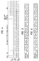
- Figs. 5 to 8 show results of measurement of the transmittance of the electromagnetic wave when the antennas are arranged in the radome having the arrester bonded thereto as shown in Figs. 2 and 3 and the azimuth is changed by 22.5 degrees at a time.
- a receiving C/N ratio by one antenna not covered by the radome having the arrester bonded thereto is 11 dB.
- the direction of the electromagnetic wave relative to the radome is oriented as shown in Fig. 9.
- the antenna is controlled and driven to be oriented as shown in Figs. 2 and 3. This corresponds to the angle 0 degree of the measurement.
- the tables of Figs. 5 to 8 show results of measurement of the transmittance of the electromagnetic wave when the antennas are arranged in the radome having the arrester bonded thereto as shown in Figs. 2 and 3 and the azimuth is changed by 22.5 degrees at a time.
- a receiving C/N ratio by one antenna not covered by the radome having the arrester bonded thereto
- the receiving C/N ratio of the antenna mounted at the front of the radome is 9.5 dB and the receiving C/N ratio of the antenna mounted at the rear is 8.75 dB.
- the receiving C/N ratio is 1.5 dB lower than that attained when the radome is not attached because of the affect of the radome and the arrester.
- the receiving C/N ratio is 2.25 dB lower than that attained when the radome is not attached because of the affect by the two arresters arranged between the antennas.
- the receiving C/N ratios are different between the front mounting and the rear mounting depending on the angle of incidence of the electromagnetic wave, but when the radar charts of the antenna gains of Figs. 7 and 8 are combined, it provides an antenna gain which is uniform in substantially all directions. Namely, by combining the received signals from the two antennas, the output C/N is substantially constant.
- the satellite broadcast can be watched on the monitor 19.
- Figs. 10 and 11 show a mount position of the radome on the aeroplane.
Landscapes
- Engineering & Computer Science (AREA)
- Physics & Mathematics (AREA)
- Astronomy & Astrophysics (AREA)
- Aviation & Aerospace Engineering (AREA)
- General Physics & Mathematics (AREA)
- Computer Networks & Wireless Communication (AREA)
- Signal Processing (AREA)
- Remote Sensing (AREA)
- Variable-Direction Aerials And Aerial Arrays (AREA)
- Details Of Aerials (AREA)
Claims (9)
- Mobiler Empfänger für eine Satellitensendung, wobei der mobile Empfänger umfaßt:dadurch gekennzeichnet, daß:ein Radom (1);eine Vielzahl von zum Empfangen der Satellitensendung aufgebauten Richtantennen (3), wobei jede solche Antenne durch das Radom (1) abgedeckt und an einem Antrieb (9) angebracht ist, der Neigungs- und Drehwinkel der jeweiligen Antenne einstellt;eine Navigationseinheit (5) zum Erzeugen eines eine Position und eine Fluglage eines Luftfahrzeuges darstellenden Navigationssignals;Steuermittel (7) zum Erzeugen eines Antennen-Steuersignals zum Steuern der Antennenantriebe (9) aufgrund des Navigationssignals von der Navigationseinheit (5) und vorher gespeicherter Information, welche eine Position des Satelliten bezeichnet, wobei die Antennenantriebe (9) die Neigungs- und Drehwinkel der Antennen (3) gemäß dem Antennen-Steuersignal von dem Steuermittel (7) so einstellen, daß sie die Antennen (3) zu dem Satelliten hin ausrichten; undKombinationsmittel (11) zum phasenkonformen Kombinieren der Ausgangssignale von den Antennen,die Vielzahl von Richtantennen in Längsrichtung des Radoms mit Abstand voneinander angebracht ist; unddaß das Radom eine Aufspanneinrichtung umfaßt, welche Aufspanneinrichtung (15) ein in Längsrichtung an dem Radom (1) ausgerichtetes Metallteil und eine Vielzahl von in Querrichtung an dem Radom ausgerichteten und das in Längsrichtung ausgerichtete Metallteil an in Längsrichtung längs des Radoms Abstand aufweisenden Kreuzungspunkten kreuzenden Metallteilen enthält, wobei jede Antenne (3) unterhalb eines jeweiligen der beiden äußersten Kreuzungspunkte gelegen ist.
- Mobiler Empfänger nach Anspruch 1, bei dem das Kombinationsmittel (11) die Ausgangssignale in einem Zwischenfrequenzband kombiniert.
- Mobiler Empfänger nach Anspruch 1 oder 2, bei dem die Antennen (3) so angebracht sind, daß die Kombination der Ausgangssignale von den Antennen einen im wesentlichen konstanten C/N-Pegel besitzt, ohne Rücksicht auf die Position und Fluglage des Luftfahrzeuges während des Empfangs der Satellitensendung.
- Mobiler Empfänger nach Anspruch 1, 2 oder 3, bei dem die Antennen (3) so angebracht sind, daß die Kombination der Ausgangssignale von den Antennen mindestens den gleichen oder einen größeren C/N-Wert aufweist als der Ausgabe-C/N-Wert irgendeiner Einzelantenne einer einzelnen Richtantenne ist, ohne Rücksicht auf Position und Fluglage des Luftfahrzeuges während des Empfangs der Satellitensendung.
- Mobiler Empfänger nach einem der vorangehenden Ansprüche, bei dem die Antennen (3) planare Richtantennen sind.
- Mobiler Empfänger nach einem der vorangehenden Ansprüche, bei dem die Navigationseinheit (5) eine Trägheits-Navigationseinheit ist.
- Mobiler Empfänger nach einem der vorangehenden Ansprüche, bei dem eine der Antennen (3) zu der Vorderseite des Radoms (1) hin und eine andere der Antennen (3) zu der Rückseite des Radoms (1) hin angeordnet ist.
- Mobiler Empfänger nach Anspruch 7, bei dem das Aufspanngerät (15) vier Quer-Metallteile umfaßt, von denen zwei zwischen der vorderen und der hinteren Antenne (3) an dem Radom (1) angebracht sind.
- Luftfahrzeug, das einen mobilen Empfänger nach einem der Ansprüche 1 bis 8 umfaßt.
Applications Claiming Priority (4)
| Application Number | Priority Date | Filing Date | Title |
|---|---|---|---|
| JP4320445A JPH06169274A (ja) | 1992-11-30 | 1992-11-30 | 衛星放送移動受信装置 |
| JP320445/92 | 1992-11-30 | ||
| JP320444/92 | 1992-11-30 | ||
| JP32044492A JP3306758B2 (ja) | 1992-11-30 | 1992-11-30 | 衛星放送移動受信装置 |
Publications (2)
| Publication Number | Publication Date |
|---|---|
| EP0600699A1 EP0600699A1 (de) | 1994-06-08 |
| EP0600699B1 true EP0600699B1 (de) | 1999-05-06 |
Family
ID=26570089
Family Applications (1)
| Application Number | Title | Priority Date | Filing Date |
|---|---|---|---|
| EP93309519A Expired - Lifetime EP0600699B1 (de) | 1992-11-30 | 1993-11-29 | Mobiler Empfänger für Satellitenfunk |
Country Status (4)
| Country | Link |
|---|---|
| US (1) | US5678171A (de) |
| EP (1) | EP0600699B1 (de) |
| CA (1) | CA2110205C (de) |
| DE (1) | DE69324771T2 (de) |
Families Citing this family (51)
| Publication number | Priority date | Publication date | Assignee | Title |
|---|---|---|---|---|
| FR2735304B1 (fr) * | 1995-06-12 | 1997-07-11 | Alcatel Espace | Systeme de communication par satellites a defilement, satellite, station et terminal y inclus |
| GB2306055B (en) * | 1995-10-06 | 2000-01-12 | Roke Manor Research | Improvements in or relating to antennas |
| US5771015A (en) * | 1995-11-20 | 1998-06-23 | Kirtman; Stuart E. | Controllable antenna system |
| DE19543321B4 (de) * | 1995-11-21 | 2006-11-16 | Diehl Stiftung & Co.Kg | Verfahren und Einrichtung zum drahtlosen Austausch von Informationen zwischen Stationen |
| US5809457A (en) * | 1996-03-08 | 1998-09-15 | The United States Of America As Represented By The Administrator Of The National Aeronautics And Space Administration | Inertial pointing and positioning system |
| US5760819A (en) * | 1996-06-19 | 1998-06-02 | Hughes Electronics | Distribution of a large number of live television programs to individual passengers in an aircraft |
| US5995041A (en) * | 1996-12-30 | 1999-11-30 | At&T Corp. | Communication system with direct link to satellite |
| US5949369A (en) * | 1996-12-30 | 1999-09-07 | At & T Corp, | Portable satellite phone having directional antenna for direct link to satellite |
| BR9809369A (pt) * | 1997-04-30 | 2000-07-04 | Cit Alcatel | Sistema de antenas, notadamente para rastreamento de satélites em movimento |
| FR2764444B1 (fr) * | 1997-06-09 | 1999-09-24 | Alsthom Cge Alcatel | Systeme d'antennes, notamment pour pointage de satellites defilants |
| JP3052897B2 (ja) * | 1997-07-01 | 2000-06-19 | 日本電気株式会社 | 衛星捕捉・追尾装置 |
| US5952968A (en) * | 1997-09-15 | 1999-09-14 | Rockwell International Corporation | Method and apparatus for reducing jamming by beam forming using navigational data |
| US6061562A (en) * | 1997-10-30 | 2000-05-09 | Raytheon Company | Wireless communication using an airborne switching node |
| US6023242A (en) * | 1998-07-07 | 2000-02-08 | Northern Telecom Limited | Establishing communication with a satellite |
| JP3603995B2 (ja) * | 1999-03-31 | 2004-12-22 | シャープ株式会社 | 高周波無線通信装置 |
| US8176520B1 (en) * | 2000-01-28 | 2012-05-08 | Rockwell Collins, Inc. | Communication system and method for a mobile platform |
| US6810527B1 (en) | 1999-09-27 | 2004-10-26 | News America, Inc. | System and method for distribution and delivery of media context and other data to aircraft passengers |
| DE10195987T1 (de) * | 2000-03-28 | 2003-10-30 | Lockheed Corp | Zugangssystem für Direkt-Rundstrahlsatellitenservices |
| US7472409B1 (en) * | 2000-03-28 | 2008-12-30 | Lockheed Martin Corporation | System for access to direct broadcast satellite services |
| US20030192052A1 (en) * | 2000-04-07 | 2003-10-09 | Live Tv, Inc. | Aircraft in-flight entertainment system generating a pricing structure for available features, and associated methods |
| US8803971B2 (en) * | 2000-04-07 | 2014-08-12 | Livetv, Llc | Aircraft system providing passenger entertainment and surveillance features, and associated methods |
| US20030229897A1 (en) * | 2000-04-07 | 2003-12-11 | Live Tv, Inc. | Aircraft in-flight entertainment system providing passenger specific advertisements, and associated methods |
| US7587733B2 (en) * | 2000-04-07 | 2009-09-08 | Livetv, Llc | Aircraft in-flight entertainment system providing weather information and associated methods |
| US20030200547A1 (en) * | 2000-04-07 | 2003-10-23 | Live Tv, Inc. | Aircraft in-flight entertainment system receiving terrestrial television broadcast signals and associated methods |
| US6661353B1 (en) | 2001-03-15 | 2003-12-09 | Matsushita Avionics Systems Corporation | Method for displaying interactive flight map information |
| US20020159399A1 (en) * | 2001-04-27 | 2002-10-31 | Stephenson Gary V. | Combined fixed satellite service and mobile platform satellite service communication system |
| US6483458B1 (en) * | 2001-05-30 | 2002-11-19 | The Boeing Company | Method for accurately tracking and communicating with a satellite from a mobile platform |
| FR2836607B1 (fr) * | 2002-02-22 | 2004-05-28 | Thales Sa | Systeme antennaire pour liaisons entre vehicule mobile et objets aeriens |
| FR2838243B1 (fr) * | 2002-04-09 | 2006-06-02 | Thales Sa | Systeme antennaire modulaire |
| IL154525A (en) * | 2003-02-18 | 2011-07-31 | Starling Advanced Comm Ltd | Low profile satellite communications antenna |
| GB2402553B (en) | 2003-06-06 | 2007-06-20 | Westerngeco Seismic Holdings | A segmented antenna system for offshore radio networks and method of using the same |
| US7454202B2 (en) * | 2004-08-10 | 2008-11-18 | The Boeing Company | Low data rate mobile platform communication system and method |
| IL171450A (en) * | 2005-10-16 | 2011-03-31 | Starling Advanced Comm Ltd | Antenna board |
| IL174549A (en) * | 2005-10-16 | 2010-12-30 | Starling Advanced Comm Ltd | Dual polarization planar array antenna and cell elements therefor |
| GB2443463B (en) * | 2006-11-03 | 2010-12-08 | Vodafone Plc | Mobile telecommunications |
| US8917207B2 (en) | 2007-10-16 | 2014-12-23 | Livetv, Llc | Aircraft in-flight entertainment system having a multi-beam phased array antenna and associated methods |
| EP2441229B1 (de) | 2009-06-11 | 2020-05-06 | Panasonic Avionics Corporation | System und verfahren zur bereitstellung von sicherheit auf einer beweglichen plattform |
| EP2563661B1 (de) | 2010-04-27 | 2014-12-10 | Panasonic Avionics Corporation | Einsatzsystem und verfahren für benutzerschnittstellenvorrichtungen |
| ITRM20110143A1 (it) * | 2011-03-24 | 2012-09-25 | Spacesys Di Giorgio Perrotta | Procedimento di puntamento fra un'antenna di teminale mobile e un satellite e relativa apparecchiatura |
| KR101295643B1 (ko) * | 2011-11-02 | 2013-08-12 | 한국전자통신연구원 | Gps 신호 수신 장치 및 그 방법 |
| US9755295B2 (en) * | 2012-05-01 | 2017-09-05 | Avago Technologies General Ip (Singapore) Pte. Ltd. | Antenna configured for use in a wireless transceiver |
| CA2831325A1 (en) | 2012-12-18 | 2014-06-18 | Panasonic Avionics Corporation | Antenna system calibration |
| EP2954595B1 (de) | 2013-02-11 | 2023-05-24 | Gogo Business Aviation LLC | Mehrantennensystem und verfahren für mobile plattformen |
| CA2838861A1 (en) | 2013-02-12 | 2014-08-12 | Panasonic Avionics Corporation | Optimization of low profile antenna(s) for equatorial operation |
| CA2841685C (en) | 2013-03-15 | 2021-05-18 | Panasonic Avionics Corporation | System and method for providing multi-mode wireless data distribution |
| JPWO2016194127A1 (ja) * | 2015-06-02 | 2017-06-22 | 三菱電機株式会社 | アンテナ装置 |
| KR101694261B1 (ko) * | 2015-09-09 | 2017-01-23 | 현대자동차주식회사 | 안테나 장치 및 상기 안테나 장치를 이용하는 차량 |
| FR3050978B1 (fr) * | 2016-05-03 | 2019-09-06 | Dassault Aviation | Dispositif de support d'un equipement radioelectrique d'un aeronef, systeme radioelectrique et aeronef |
| FR3054934B1 (fr) * | 2016-08-03 | 2019-07-05 | Airbus Operations | Systeme d'emission et/ou de reception d'ondes electromagnetiques embarque dans un aeronef |
| US10637135B2 (en) * | 2017-05-09 | 2020-04-28 | The Boeing Company | Aircraft radome apparatuses and methods |
| FR3099001A1 (fr) * | 2019-07-19 | 2021-01-22 | Airbus Defence And Space Sas | Aérodyne avec antenne et procédé d’agencement associé |
Family Cites Families (11)
| Publication number | Priority date | Publication date | Assignee | Title |
|---|---|---|---|---|
| IT1063831B (it) * | 1975-06-23 | 1985-02-18 | Nippon Electric Co | Impianto ricevente a diversita spaziale |
| JPS59189730A (ja) * | 1983-04-11 | 1984-10-27 | Nippon Denso Co Ltd | 移動体に装備したラジオやテレビジョン等受信装置の受信アンテナのための電波受信方向制御装置 |
| JPS6375687A (ja) * | 1986-09-19 | 1988-04-06 | Tech Res & Dev Inst Of Japan Def Agency | スポツトライトマツピングレ−ダ装置 |
| US4841303A (en) * | 1987-07-01 | 1989-06-20 | Mobile Satellite Corporation | Low cost method and system for automatically steering a mobile directional antenna |
| JP2580832B2 (ja) * | 1990-04-19 | 1997-02-12 | 日本電気株式会社 | 移動体搭載アンテナ制御装置 |
| JPH04174385A (ja) * | 1990-11-06 | 1992-06-22 | Aisin Seiki Co Ltd | 移動体上アンテナの姿勢制御装置 |
| FI91028C (fi) * | 1991-10-30 | 1994-04-25 | Valtion Teknillinen | Satelliittiantennijärjestely |
| FI90927C (fi) * | 1991-10-30 | 1994-04-11 | Valtion Teknillinen | Satelliittiantennijärjestely |
| US5347286A (en) * | 1992-02-13 | 1994-09-13 | Trimble Navigation Limited | Automatic antenna pointing system based on global positioning system (GPS) attitude information |
| US5323170A (en) * | 1992-10-09 | 1994-06-21 | M & N Aerospace, Inc. | Radomes having vinyl foam core construction |
| US5296862A (en) * | 1992-11-18 | 1994-03-22 | Winegard Company | Method for automatically positioning a satellite dish antenna to satellites in a geosynchronous belt |
-
1993
- 1993-11-29 CA CA002110205A patent/CA2110205C/en not_active Expired - Fee Related
- 1993-11-29 EP EP93309519A patent/EP0600699B1/de not_active Expired - Lifetime
- 1993-11-29 DE DE69324771T patent/DE69324771T2/de not_active Expired - Fee Related
-
1996
- 1996-05-08 US US08/646,560 patent/US5678171A/en not_active Expired - Fee Related
Also Published As
| Publication number | Publication date |
|---|---|
| CA2110205C (en) | 1999-11-23 |
| US5678171A (en) | 1997-10-14 |
| DE69324771T2 (de) | 1999-09-09 |
| CA2110205A1 (en) | 1994-05-31 |
| DE69324771D1 (de) | 1999-06-10 |
| EP0600699A1 (de) | 1994-06-08 |
Similar Documents
| Publication | Publication Date | Title |
|---|---|---|
| EP0600699B1 (de) | Mobiler Empfänger für Satellitenfunk | |
| US7109937B2 (en) | Phased array planar antenna and a method thereof | |
| US6023242A (en) | Establishing communication with a satellite | |
| KR20010020390A (ko) | 이동 위성 성단을 위한 터미널-안테나 장치 | |
| EP0373604B1 (de) | Antennensystem mit Richtungsverfolgung | |
| US6400315B1 (en) | Control system for electronically scanned phased array antennas with a mechanically steered axis | |
| US20040196203A1 (en) | Partly interleaved phased arrays with different antenna elements in central and outer region | |
| US6911949B2 (en) | Antenna stabilization system for two antennas | |
| CN111427072B (zh) | 浮空器平台的gnss掩星信号连续接收方法及接收天线系统 | |
| EP0971241B1 (de) | Digitales Weltraumfahrzeugantennen-Nachführsystem | |
| US20220082686A1 (en) | Satellite constellation systems and methods for combined aviation and weather surveillance | |
| US7050019B1 (en) | Concentric phased arrays symmetrically oriented on the spacecraft bus for yaw-independent navigation | |
| EP0421722B1 (de) | Entfaltbares Weltraumantennensystem mit Vielfach-Strahlungskeulen | |
| JP3306758B2 (ja) | 衛星放送移動受信装置 | |
| EP0836290A2 (de) | Satellitenkommunikationsverfahren mit Satelliten auf zirkularen Laufbahnen die mit dem Äquator geneigt sind und mit einer Periode der Erde gleich | |
| Densmore et al. | K/K/sub a/-band antenna system for mobile satellite service | |
| CA2121229C (en) | Antenna apparatus | |
| Ilcev | Antenna systems for mobile satellite applications | |
| CN118645811A (zh) | 一种俯仰波束自适应调节的接收天线装置及使用方法 | |
| JPH06169274A (ja) | 衛星放送移動受信装置 | |
| Ilčev et al. | Antenna Systems and Propagation | |
| GB2379110A (en) | Determining orientation | |
| Law et al. | An electronically-stabilized 915 MHz phased array antenna for ship-borne atmospheric wind profiling | |
| Densmore et al. | K-and Ka-band mobile-vehicular satellite-tracking reflector antenna system for the NASA ACTS mobile terminal | |
| Sullivan | Dual Beam Single Axis Tracking Antenna for Tracking Telemetry Instrumented Airborne Vehicles |
Legal Events
| Date | Code | Title | Description |
|---|---|---|---|
| PUAI | Public reference made under article 153(3) epc to a published international application that has entered the european phase |
Free format text: ORIGINAL CODE: 0009012 |
|
| AK | Designated contracting states |
Kind code of ref document: A1 Designated state(s): DE FR GB |
|
| RIN1 | Information on inventor provided before grant (corrected) |
Inventor name: NAKAMURA, HISAJI Inventor name: ONO, OSAMU Inventor name: FUJITA, MASARU, C/O NIPPON HOSO KYOKAI Inventor name: TOYAMA, NOBORU, C/O NIPPON HOSO KYOKAI |
|
| 17P | Request for examination filed |
Effective date: 19941004 |
|
| 17Q | First examination report despatched |
Effective date: 19961009 |
|
| GRAG | Despatch of communication of intention to grant |
Free format text: ORIGINAL CODE: EPIDOS AGRA |
|
| GRAG | Despatch of communication of intention to grant |
Free format text: ORIGINAL CODE: EPIDOS AGRA |
|
| GRAG | Despatch of communication of intention to grant |
Free format text: ORIGINAL CODE: EPIDOS AGRA |
|
| GRAH | Despatch of communication of intention to grant a patent |
Free format text: ORIGINAL CODE: EPIDOS IGRA |
|
| GRAH | Despatch of communication of intention to grant a patent |
Free format text: ORIGINAL CODE: EPIDOS IGRA |
|
| GRAA | (expected) grant |
Free format text: ORIGINAL CODE: 0009210 |
|
| AK | Designated contracting states |
Kind code of ref document: B1 Designated state(s): DE FR GB |
|
| REF | Corresponds to: |
Ref document number: 69324771 Country of ref document: DE Date of ref document: 19990610 |
|
| ET | Fr: translation filed | ||
| PLBE | No opposition filed within time limit |
Free format text: ORIGINAL CODE: 0009261 |
|
| STAA | Information on the status of an ep patent application or granted ep patent |
Free format text: STATUS: NO OPPOSITION FILED WITHIN TIME LIMIT |
|
| 26N | No opposition filed | ||
| REG | Reference to a national code |
Ref country code: GB Ref legal event code: IF02 |
|
| PGFP | Annual fee paid to national office [announced via postgrant information from national office to epo] |
Ref country code: FR Payment date: 20021108 Year of fee payment: 10 |
|
| PGFP | Annual fee paid to national office [announced via postgrant information from national office to epo] |
Ref country code: GB Payment date: 20021127 Year of fee payment: 10 |
|
| PGFP | Annual fee paid to national office [announced via postgrant information from national office to epo] |
Ref country code: DE Payment date: 20021205 Year of fee payment: 10 |
|
| PG25 | Lapsed in a contracting state [announced via postgrant information from national office to epo] |
Ref country code: GB Free format text: LAPSE BECAUSE OF NON-PAYMENT OF DUE FEES Effective date: 20031129 |
|
| PG25 | Lapsed in a contracting state [announced via postgrant information from national office to epo] |
Ref country code: DE Free format text: LAPSE BECAUSE OF NON-PAYMENT OF DUE FEES Effective date: 20040602 |
|
| GBPC | Gb: european patent ceased through non-payment of renewal fee |
Effective date: 20031129 |
|
| PG25 | Lapsed in a contracting state [announced via postgrant information from national office to epo] |
Ref country code: FR Free format text: LAPSE BECAUSE OF NON-PAYMENT OF DUE FEES Effective date: 20040730 |
|
| REG | Reference to a national code |
Ref country code: FR Ref legal event code: ST |