EP0600506A2 - Dépôt par panneaux coulissants - Google Patents
Dépôt par panneaux coulissants Download PDFInfo
- Publication number
- EP0600506A2 EP0600506A2 EP93119527A EP93119527A EP0600506A2 EP 0600506 A2 EP0600506 A2 EP 0600506A2 EP 93119527 A EP93119527 A EP 93119527A EP 93119527 A EP93119527 A EP 93119527A EP 0600506 A2 EP0600506 A2 EP 0600506A2
- Authority
- EP
- European Patent Office
- Prior art keywords
- sliding wall
- sliding
- profile
- wall
- depot
- Prior art date
- Legal status (The legal status is an assumption and is not a legal conclusion. Google has not performed a legal analysis and makes no representation as to the accuracy of the status listed.)
- Withdrawn
Links
Images

Classifications
-
- A—HUMAN NECESSITIES
- A47—FURNITURE; DOMESTIC ARTICLES OR APPLIANCES; COFFEE MILLS; SPICE MILLS; SUCTION CLEANERS IN GENERAL
- A47F—SPECIAL FURNITURE, FITTINGS, OR ACCESSORIES FOR SHOPS, STOREHOUSES, BARS, RESTAURANTS OR THE LIKE; PAYING COUNTERS
- A47F7/00—Show stands, hangers, or shelves, adapted for particular articles or materials
- A47F7/0042—Show stands, hangers, or shelves, adapted for particular articles or materials for flat articles, e.g. panels, tiles
-
- A—HUMAN NECESSITIES
- A47—FURNITURE; DOMESTIC ARTICLES OR APPLIANCES; COFFEE MILLS; SPICE MILLS; SUCTION CLEANERS IN GENERAL
- A47B—TABLES; DESKS; OFFICE FURNITURE; CABINETS; DRAWERS; GENERAL DETAILS OF FURNITURE
- A47B53/00—Cabinets or racks having several sections one behind the other
Definitions
- the invention relates to a sliding wall depot, for example for storing flat objects, e.g. for hanging precious pictures.
- a sliding wall depot for example for storing flat objects, e.g. for hanging precious pictures.
- a magazine such a depot enables space-saving storage and the selective pulling out of the objects fastened to sliding walls.
- a sliding wall depot is used, for example, in museums that only permanently display a small part of their holdings.
- the non-exhibited pictures must be kept in depots that allow space-saving storage and at the same time permanent access to the works.
- the sliding walls are arranged closely, it can happen that valuable pictures which are hung on a sliding wall collide with pictures of the neighboring sliding wall when the sliding wall is pulled out. It should be taken into account that the sliding walls have very large dimensions, for example approximately 4 x 4 m, although even relatively small tolerance deviations can have considerable effects.
- guide elements are attached to the floor in known sliding walls, which guide the sliding walls on both sides.
- the invention has for its object to provide a sliding wall depot in which the sliding walls can have a small mutual distance without the risk of striking adjacent objects.
- the sliding wall depot according to the invention enables the use of large-sized sliding walls which are composed of several profile frames. Thereby A modular construction of the sliding walls is made possible, which can be screwed together on one level.
- the profile strip is required as the only continuous part with the length of the sliding wall.
- the parts of a sliding wall depot can therefore be delivered with a small volume of space.
- the stationary guide elements In the assembled state, the stationary guide elements only engage the profile bar which is arranged at the lower end of the sliding wall and do not come into contact with other parts, in particular not with the profile frame of the sliding wall, the dimensions of which fluctuate due to tolerances. As a result, the sliding wall cannot be caused to vibrate when passing through one of the adjacent frame parts with different external dimensions, thereby protecting the objects suspended on the sliding wall. Since no shocks and vibrations are caused by the stationary guide elements when moving the sliding wall, it is possible to reduce the distance between two adjacent sliding walls to a minimum without the risk of striking adjacent objects.
- the guide elements support the sliding wall on both sides.
- the guide elements are suitably arranged only at the front end of the displacement path, so that there is an interaction of guide elements and profile strip over the entire length of the sliding wall.
- the sliding wall advantageously has a wheel which is pressed down by a resilient pressing device and which is fixedly oriented in the direction of displacement.
- the downward pressure ensures that the wheel is permanently in contact with the ground stands.
- the wheel guides the sliding wall outside the guide elements, in particular when the sliding wall is pulled up or during the movement of the sliding wall.
- the wheel pressed against the ground counteracts swinging, in particular transverse to the plane of displacement, or tilting of the sliding wall.
- Spring-damped stop elements are provided at both ends of the displacement path. If the sliding wall is moved back too quickly to its starting position or to its pulled-out position, it is braked and does not come to a sudden stop. This protects the objects hung on it.
- the displacement path is suitably limited so that the sliding wall does not come out of engagement with the guide elements, so that threading the sliding wall between the guide elements after pulling out is not necessary.
- the sliding walls or the profile frames forming them can be provided on one or both sides with supporting grids.
- the support grids allow objects of various dimensions and weights to be hung easily and easily accessible. Also a quick and provisional storage of objects, e.g. with the help of hooks, is easily possible.
- the sliding walls suitably have the same dimensions and are arranged equidistantly.
- the rails are preferably provided so long that two sliding walls are arranged opposite each other in a storage area and are alternately slidable along the common rail. One of the two sliding walls can be pulled into a viewing area between the two storage areas.
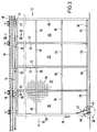
- the sliding wall depot shown in FIG. 1 is intended for storing pictures or other, essentially flat objects, such as carpets, photographs, prints, engravings, glass, etc.
- the sliding wall depot has a plurality of rectangular sliding walls 12 arranged next to one another at the same distance.
- Each sliding wall 12 hangs from a rail 14 along which the sliding wall 12 is displaceable without touching the floor of the room.
- the rails 14 of the sliding wall depot run parallel and equidistant.
- On each rail 14 hangs a sliding wall 12.
- the sliding walls 12 in FIG. 1 - with the exception of the sliding wall 12 '- are arranged next to one another on the (right) end of the rails 14 in a storage area.
- the arrow 10 indicates the direction of displacement of the sliding walls 12 out of the storage area.
- the space available underneath the rails 14 in the vicinity of the sliding walls 12 arranged in the storage area serves as a viewing area 11, for example for the selection of sliding walls 12 pulled out on attached art objects.
- the sliding wall 12 'protrudes a bit into the viewing area 11. Art objects are suspended and removed with the sliding wall 12 pulled out.
- the rail 14 is a continuous cylindrical rod with a full profile, which is supported by a plurality of spaced-apart rail holders 16 which protrude from a horizontal profile beam 18.
- the profile beam 18 is fastened horizontally to the ceiling of the room wall with the aid of adjustable anchors, which enable the profile beam to be adjusted precisely in the horizontal direction.
- the sliding walls 12 have a height of approximately 4 m and a length of approximately 4 m. Each sliding wall 12 is screwed together from four profile frames 20 arranged one behind the other in the direction of displacement 10, which have essentially the same dimensions and which extend over the entire height of the sliding wall 12.
- the profile frame 20 each have a front profile bar 22 which is vertical in the direction of displacement 10 and one vertical rear profile strip 24, which are connected to one another via cross strips 26, a cross strip 26 engaging at the upper and lower ends of the front and rear profile strips 22 and 24, respectively.
- the profile frame 20 has a rectangular shape.
- the strips 22, 24, 26 have a rectangular cross section and are hollow.
- a thicker, also hollow end strip 28 with a rectangular cross section is used instead of the front profile strip 22.
- the rear profile strip 24 is replaced by a thicker cover strip 28.
- the two end strips 28 protrude below the bottom transverse strips 26 of the profile frame 20 by approximately one transverse strip width.
- a profile strip 30 runs, which is formed in one piece.
- the profile strip 30 consists of a tube with a rectangular cross section, the outer sides of which are flat.
- the profile strip 30 is attached at a low height above the floor parallel to this directly on the lowest cross strips 26.
- a handle 29 is attached to the front of the front end strip 28.
- Supporting grids 36 are attached to the profile frame 20 on both sides and have such a rigidity that they are not bulged even under high weight loads. It is not absolutely necessary to attach a support grid 36 over the entire surface of the sliding wall 12. Flat objects, in particular, can be fastened well and securely to the supporting grids 36, e.g. with the help of screw-on angle elements. The objects can then no longer convert their inertia when the sliding wall 12 moves into their own relative movement to the sliding wall 12.
- the front profile frame 20 has two, the other profile frames 20 each have a connecting element 32 for connecting the top cross bar 26 of the respective profile frame 20 with a ball bushing 34.
- the ball bushing 34 encompasses the rail 14 almost completely and only has a recess on its upper side for passing the rail holder 16.
- the connecting elements 32 are in each case attached to the uppermost transverse strips 26 at the rear, and to the uppermost transverse strip 26 of the foremost profile frame 20 at the front and rear.
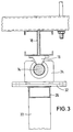
- a wheel 40 is arranged in the front area of the sliding wall 12 and is pressed downwards by a compressed gas spring 42, which is attached to the front end strip 28 via a joint 44.
- the wheel axis 46 of the wheel 40 is supported at both ends on a holder 48 which in turn starts from the protruding leg 50a of an angle piece 50.
- the other joint leg 50b of the right-angled angle piece 50 can be pivoted on the upper edge of the lowermost cross bar 26 of the foremost profile frame 20 about a horizontal axis 52 running perpendicular to the plane of the sliding wall.
- the angle piece 50, the holder 48 and the wheel 40 are attached in such a way that the angle piece 50 is oriented essentially upwards with its joint leg 50b and essentially horizontally with its projecting leg 50a.
- the wheel 40 is arranged in the center and non-rotatably in a notch 38.
- the notch 38 consists of a cutout 38a in the lowermost cross bar 26 of the foremost profile frame 20, in which only the side boundaries are retained, and a cutout 38b in the profile bar 30, which is immediate runs under the recess 38a, which are congruent with one another in plan view. Both recesses 38a and 38b form a vertical channel with an essentially rectangular cross section. Due to the bias by the gas spring 42, the wheel 40 is always in contact with the ground. The wheel 40 can be pivoted upward against the action of the compressed gas spring 42. However, it is arranged in a rotationally fixed manner, ie it can only rotate about its wheel axis 46.
- the wheel 40 has soft and wear-resistant tires.
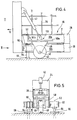
- a guide element 60 designed as a roller is arranged on both sides of the profile strip 30 of the sliding wall 12.
- the rollers 60 have a cylindrical shape and are rotatable about their vertical axis 62.
- the rollers 60 are arranged on shaft pieces 64 which are fastened to the depot bottom by means of a base plate 66.
- the rollers 60 are made of flexible, resilient material, which is encased by an abrasion-resistant material, and lie directly on the two side flanks of the profile strip 30, but below the path of movement of the bottom cross strips 26 of the profile frame 20. Profile elements other than the profile strip 30 do not engage the rollers 60.
- the accuracy of the movement of the sliding wall 12 is thus ensured by the uniformity of the flanks of the profile strip 30 and the roller circumference of the rollers 60.
- the base plates 66 and the shaft pieces 64 are stationary and cannot be moved.
- the number of rollers 60 arranged on both sides of the sliding wall 12 is not limited to one pair of rollers. Rather, it is possible to
- the pair of rollers 60 is arranged at the same height and on a straight line perpendicular to the plane of the sliding wall 12. This ensures optimal running of the sliding door 12.
- the pair of rollers 60 is arranged so that it is arranged in front of the wheel 40 in the front area of the sliding wall 12 located in the storage area. This makes it possible to provide a maximum travel path of the sliding wall 12 if the travel path is restricted in such a way that the rollers 60 are still in engagement with the profiled strip 30 even when the sliding wall 12 is completely displaced in the direction of displacement 10.
- the travel of the sliding wall 12 then corresponds to the length of the profile strip 30.
- the rollers 60 are preferably arranged immediately behind the front end strip 28 when the sliding wall 12 is in the starting position. The sliding wall 12 can be moved in the direction of displacement 10 to a position in which the rear end strip 28 is located directly behind the rollers 60.
- the wheel 40 is pressed permanently against the floor of the room by the compressed gas spring 42 during the displacement process. Uneven floors are absorbed by the resilient part of the compressed gas spring 42, so that the wheel 40 remains in constant contact with the room floor and rolls on it. This has the advantageous effect that a lateral drift of the sliding wall 12 is inhibited even when the sliding wall 12 is largely pulled out. This means that even when the sliding wall 12 is completely pulled out, a pendulum movement cannot occur in the front area of the sliding wall 12.
- the sliding wall 12 can also be loaded on one side or strongly asymmetrically without impairing its orientation.
- the number of wheels is not limited to one wheel. Rather, it is possible to arrange a wheel also in the rear area of the sliding wall 12.
- a resilient stop element ensures that the sliding wall 12 is braked and steadily and quietly returned to its initial position even when the operation is rough becomes.
- the distance between adjacent sliding walls is not necessarily the same for each adjacent sliding wall, it is rather to be determined as a function of the objects to be attached to the sliding walls, so that essentially twice the thickness of the suspended objects is selected.
Landscapes
- Support Devices For Sliding Doors (AREA)
Applications Claiming Priority (2)
| Application Number | Priority Date | Filing Date | Title |
|---|---|---|---|
| DE9216537U | 1992-12-04 | ||
| DE9216537U DE9216537U1 (fr) | 1992-12-04 | 1992-12-04 |
Publications (2)
| Publication Number | Publication Date |
|---|---|
| EP0600506A2 true EP0600506A2 (fr) | 1994-06-08 |
| EP0600506A3 EP0600506A3 (fr) | 1994-12-21 |
Family
ID=6886767
Family Applications (1)
| Application Number | Title | Priority Date | Filing Date |
|---|---|---|---|
| EP93119527A Withdrawn EP0600506A3 (fr) | 1992-12-04 | 1993-12-03 | DépÔt par panneaux coulissants. |
Country Status (2)
| Country | Link |
|---|---|
| EP (1) | EP0600506A3 (fr) |
| DE (1) | DE9216537U1 (fr) |
Cited By (4)
| Publication number | Priority date | Publication date | Assignee | Title |
|---|---|---|---|---|
| FR2803729A1 (fr) * | 2000-01-19 | 2001-07-20 | Feralp | Structure de rangement a panneaux articules |
| FR2826250A1 (fr) * | 2001-06-21 | 2002-12-27 | Images Et Cadres | Dispositif de presentation de tableaux |
| CN103405045A (zh) * | 2013-07-29 | 2013-11-27 | 海发(宁波)办公设备有限公司 | 一种新型密集架 |
| US20210298494A1 (en) * | 2014-01-29 | 2021-09-30 | Liberty Hardware Mfg. Corp. | Shower door assembly display |
Families Citing this family (4)
| Publication number | Priority date | Publication date | Assignee | Title |
|---|---|---|---|---|
| ES2307354B1 (es) * | 2005-07-06 | 2009-09-18 | Insca Internacional, S.L. | Dispositivo de guiado de paneles expositores. |
| ES2319361B1 (es) * | 2006-08-04 | 2010-01-25 | Moidercar, S.L. | Expositor de paneles deslizantes. |
| ES1066327Y (es) * | 2007-10-18 | 2008-07-01 | Insca Int Sl | Dispositivo de guiado para paneles expositores |
| EP2174574A1 (fr) * | 2008-10-08 | 2010-04-14 | Moidecar, S.L. | Support démontable pour panneaux d'affichage |
Citations (2)
| Publication number | Priority date | Publication date | Assignee | Title |
|---|---|---|---|---|
| US3135570A (en) * | 1960-12-30 | 1964-06-02 | Erismann Paul | Cabinet with a pivotable door and at least one drawer |
| WO1991007338A1 (fr) * | 1989-11-09 | 1991-05-30 | Grau Gmbh & Co. | Stockeur et dispositif de stockage pour objets stockes |
-
1992
- 1992-12-04 DE DE9216537U patent/DE9216537U1/de not_active Expired - Lifetime
-
1993
- 1993-12-03 EP EP93119527A patent/EP0600506A3/fr not_active Withdrawn
Patent Citations (2)
| Publication number | Priority date | Publication date | Assignee | Title |
|---|---|---|---|---|
| US3135570A (en) * | 1960-12-30 | 1964-06-02 | Erismann Paul | Cabinet with a pivotable door and at least one drawer |
| WO1991007338A1 (fr) * | 1989-11-09 | 1991-05-30 | Grau Gmbh & Co. | Stockeur et dispositif de stockage pour objets stockes |
Cited By (8)
| Publication number | Priority date | Publication date | Assignee | Title |
|---|---|---|---|---|
| FR2803729A1 (fr) * | 2000-01-19 | 2001-07-20 | Feralp | Structure de rangement a panneaux articules |
| EP1120070A1 (fr) | 2000-01-19 | 2001-08-01 | Feralp | Structure de rangement à panneaux articulés. |
| FR2826250A1 (fr) * | 2001-06-21 | 2002-12-27 | Images Et Cadres | Dispositif de presentation de tableaux |
| CN103405045A (zh) * | 2013-07-29 | 2013-11-27 | 海发(宁波)办公设备有限公司 | 一种新型密集架 |
| CN103405045B (zh) * | 2013-07-29 | 2015-10-07 | 海发(宁波)办公设备有限公司 | 一种新型密集架 |
| US20210298494A1 (en) * | 2014-01-29 | 2021-09-30 | Liberty Hardware Mfg. Corp. | Shower door assembly display |
| US20230088215A1 (en) * | 2014-01-29 | 2023-03-23 | Liberty Hardware Mfg. Corp. | Shower door assembly display |
| US11641956B2 (en) * | 2014-01-29 | 2023-05-09 | Liberty Hardware Mfg. Corp. | Shower door assembly display |
Also Published As
| Publication number | Publication date |
|---|---|
| EP0600506A3 (fr) | 1994-12-21 |
| DE9216537U1 (fr) | 1993-01-28 |
Similar Documents
| Publication | Publication Date | Title |
|---|---|---|
| CH678168A5 (fr) | ||
| DE8426651U1 (de) | Ablage zur sicht- und griffnahen Präsentation von hintereinander angeordneten Warenpackungen | |
| AT401258B (de) | Vorrichtung zum lagern von glastafeln oder isolierglasscheiben | |
| EP0441919B1 (fr) | Element de meuble pour la mise en place dans un coin rectangulaire d'une piece | |
| EP0600506A2 (fr) | Dépôt par panneaux coulissants | |
| DE2335231A1 (de) | Standablage fuer gegenstaende | |
| CH663404A5 (en) | Method for the conveying of mass parts and apparatus for carrying out the method | |
| DE10260207B4 (de) | Sanitärhalterung | |
| EP0603151B1 (fr) | Dispositif avec casiers | |
| EP0599032A1 (fr) | Magasin de stockage pour récipients | |
| CH644257A5 (en) | Method and device for storing and dispensing articles | |
| EP0679788B1 (fr) | Chariot ainsi qu'ensemble coulissant et rail | |
| CH686690A5 (de) | Laufwerk sowie Verschiebeeinrichtung. | |
| EP0242811A2 (fr) | Table et/ou armoire installées contre un mur vertical | |
| DE3214916C2 (fr) | ||
| EP0517271A1 (fr) | Support pour un carrousel horizontal | |
| EP3085281B1 (fr) | Élement coulissant destine a ranger par coulissement un rideau ou une bache | |
| EP0502362B1 (fr) | Dispositif de blindage de tranchée | |
| DE2204759A1 (de) | Transportvorrichtung | |
| CH670749A5 (en) | Cabinet and/or table mounted on vertical wall | |
| DE3635592A1 (de) | An einer senkrechten wand montierbares schrank- und/oder tischmoebel | |
| EP0397133A2 (fr) | Dispositif destiné à modifier la position de bobines de bandes enroulées | |
| DE19548959A1 (de) | Durchlaufregal mit Trennleiste | |
| DE3151593A1 (de) | Vorrichtung zur haengenden aufbewahrung und praesentation von teppichen | |
| DE1654724C (de) | Möbel, bei dem Tragmittel zu einer gegenläufigen Bewegung miteinander gekuppelt sind |
Legal Events
| Date | Code | Title | Description |
|---|---|---|---|
| PUAI | Public reference made under article 153(3) epc to a published international application that has entered the european phase |
Free format text: ORIGINAL CODE: 0009012 |
|
| AK | Designated contracting states |
Kind code of ref document: A2 Designated state(s): AT BE CH DE ES FR GB IT LI NL |
|
| PUAL | Search report despatched |
Free format text: ORIGINAL CODE: 0009013 |
|
| AK | Designated contracting states |
Kind code of ref document: A3 Designated state(s): AT BE CH DE ES FR GB IT LI NL |
|
| 17P | Request for examination filed |
Effective date: 19950110 |
|
| GRAG | Despatch of communication of intention to grant |
Free format text: ORIGINAL CODE: EPIDOS AGRA |
|
| 17Q | First examination report despatched |
Effective date: 19960327 |
|
| GRAH | Despatch of communication of intention to grant a patent |
Free format text: ORIGINAL CODE: EPIDOS IGRA |
|
| STAA | Information on the status of an ep patent application or granted ep patent |
Free format text: STATUS: THE APPLICATION HAS BEEN WITHDRAWN |
|
| 18W | Application withdrawn |
Withdrawal date: 19961106 |