EP0599611B1 - Systèmes de conditionnement de l'air et de réfrigération sous utilisation d'un cryogène - Google Patents
Systèmes de conditionnement de l'air et de réfrigération sous utilisation d'un cryogène Download PDFInfo
- Publication number
- EP0599611B1 EP0599611B1 EP93309347A EP93309347A EP0599611B1 EP 0599611 B1 EP0599611 B1 EP 0599611B1 EP 93309347 A EP93309347 A EP 93309347A EP 93309347 A EP93309347 A EP 93309347A EP 0599611 B1 EP0599611 B1 EP 0599611B1
- Authority
- EP
- European Patent Office
- Prior art keywords
- heat exchanger
- refrigeration system
- internal combustion
- combustion engine
- fuel
- Prior art date
- Legal status (The legal status is an assumption and is not a legal conclusion. Google has not performed a legal analysis and makes no representation as to the accuracy of the status listed.)
- Expired - Lifetime
Links
Images

Classifications
-
- B—PERFORMING OPERATIONS; TRANSPORTING
- B60—VEHICLES IN GENERAL
- B60H—ARRANGEMENTS OF HEATING, COOLING, VENTILATING OR OTHER AIR-TREATING DEVICES SPECIALLY ADAPTED FOR PASSENGER OR GOODS SPACES OF VEHICLES
- B60H1/00—Heating, cooling or ventilating [HVAC] devices
- B60H1/32—Cooling devices
- B60H1/3202—Cooling devices using evaporation, i.e. not including a compressor, e.g. involving fuel or water evaporation
-
- B—PERFORMING OPERATIONS; TRANSPORTING
- B60—VEHICLES IN GENERAL
- B60H—ARRANGEMENTS OF HEATING, COOLING, VENTILATING OR OTHER AIR-TREATING DEVICES SPECIALLY ADAPTED FOR PASSENGER OR GOODS SPACES OF VEHICLES
- B60H1/00—Heating, cooling or ventilating [HVAC] devices
- B60H1/00007—Combined heating, ventilating, or cooling devices
-
- F—MECHANICAL ENGINEERING; LIGHTING; HEATING; WEAPONS; BLASTING
- F25—REFRIGERATION OR COOLING; COMBINED HEATING AND REFRIGERATION SYSTEMS; HEAT PUMP SYSTEMS; MANUFACTURE OR STORAGE OF ICE; LIQUEFACTION SOLIDIFICATION OF GASES
- F25B—REFRIGERATION MACHINES, PLANTS OR SYSTEMS; COMBINED HEATING AND REFRIGERATION SYSTEMS; HEAT PUMP SYSTEMS
- F25B19/00—Machines, plants or systems, using evaporation of a refrigerant but without recovery of the vapour
-
- F—MECHANICAL ENGINEERING; LIGHTING; HEATING; WEAPONS; BLASTING
- F25—REFRIGERATION OR COOLING; COMBINED HEATING AND REFRIGERATION SYSTEMS; HEAT PUMP SYSTEMS; MANUFACTURE OR STORAGE OF ICE; LIQUEFACTION SOLIDIFICATION OF GASES
- F25B—REFRIGERATION MACHINES, PLANTS OR SYSTEMS; COMBINED HEATING AND REFRIGERATION SYSTEMS; HEAT PUMP SYSTEMS
- F25B27/00—Machines, plants or systems, using particular sources of energy
-
- F—MECHANICAL ENGINEERING; LIGHTING; HEATING; WEAPONS; BLASTING
- F25—REFRIGERATION OR COOLING; COMBINED HEATING AND REFRIGERATION SYSTEMS; HEAT PUMP SYSTEMS; MANUFACTURE OR STORAGE OF ICE; LIQUEFACTION SOLIDIFICATION OF GASES
- F25D—REFRIGERATORS; COLD ROOMS; ICE-BOXES; COOLING OR FREEZING APPARATUS NOT OTHERWISE PROVIDED FOR
- F25D29/00—Arrangement or mounting of control or safety devices
- F25D29/001—Arrangement or mounting of control or safety devices for cryogenic fluid systems
-
- F—MECHANICAL ENGINEERING; LIGHTING; HEATING; WEAPONS; BLASTING
- F25—REFRIGERATION OR COOLING; COMBINED HEATING AND REFRIGERATION SYSTEMS; HEAT PUMP SYSTEMS; MANUFACTURE OR STORAGE OF ICE; LIQUEFACTION SOLIDIFICATION OF GASES
- F25D—REFRIGERATORS; COLD ROOMS; ICE-BOXES; COOLING OR FREEZING APPARATUS NOT OTHERWISE PROVIDED FOR
- F25D3/00—Devices using other cold materials; Devices using cold-storage bodies
- F25D3/10—Devices using other cold materials; Devices using cold-storage bodies using liquefied gases, e.g. liquid air
- F25D3/105—Movable containers
-
- B—PERFORMING OPERATIONS; TRANSPORTING
- B60—VEHICLES IN GENERAL
- B60H—ARRANGEMENTS OF HEATING, COOLING, VENTILATING OR OTHER AIR-TREATING DEVICES SPECIALLY ADAPTED FOR PASSENGER OR GOODS SPACES OF VEHICLES
- B60H1/00—Heating, cooling or ventilating [HVAC] devices
- B60H1/00642—Control systems or circuits; Control members or indication devices for heating, cooling or ventilating devices
- B60H1/00814—Control systems or circuits characterised by their output, for controlling particular components of the heating, cooling or ventilating installation
- B60H1/00878—Control systems or circuits characterised by their output, for controlling particular components of the heating, cooling or ventilating installation the components being temperature regulating devices
- B60H2001/00961—Control systems or circuits characterised by their output, for controlling particular components of the heating, cooling or ventilating installation the components being temperature regulating devices comprising means for defrosting outside heat exchangers
Definitions
- the invention relates in general to air conditionmg and refrigeration systems, and more specifically to the use of a cryogen for controlling the temperature of a conditioned space associated with stationary and transport type applications of air conditioning and refrigeration systems.
- Stationary and transport applications of air conditioning and refrigeration systems control the temperature of a conditioned space to a predetermined temperature range adjacent to a selected set point temperature, with transport applications including those associated with a vehicle, such as a straight truck, a tractor-trailer combination, a refrigerated container, and the like.
- a vehicle such as a straight truck, a tractor-trailer combination, a refrigerated container, and the like.
- Such systems conventionally utilize a chlorofluorocarbon (CFC) refrigerant in a mechanical refrigeration cycle.
- the mechanical refrigeration cycle requires a refrigerant compressor driven by a prime mover, which often includes a dedicated internal combustion engine, such as a diesel engine. Because of the suspected depleting effect of CFC's on stratospheric ozone (O 3 ), practical alternatives to the use of CFC's are being sought.
- cryogen i.e., a gas which has been compressed to a very cold liquid state, such as carbon dioxide (CO 2 ) and nitrogen (N 2 ), in air conditioning and refrigeration systems is particularly attractive because, in addition to eliminating the need for a CFC, it also eliminates the need for a compressor and associated prime mover.
- Air conditioning and refrigeration systems of which we are aware which utilize a cryogen implement a cooling cycle by circulating the cryogen through a fluid path which includes a heat exchanger which is in heat exchange relation with air from a conditioned space.
- cryogen When a heating cycle is required to hold the temperature of the conditioned space within a predetermined narrow temperature band adjacent to a selected set point temperature, or a defrost cycle is required, the cryogen is heated by a burner and associated fuel, and the heated cryogen is circulated through the fluid path and heat exchanger. Thus, cryogen is expended to the atmosphere during a cooling cycle, and cryogen plus a fuel, such as propane, diesel fuel, liquid natural gas, and the like, are expended to the atmosphere to implement heating and defrost cycles.
- a fuel such as propane, diesel fuel, liquid natural gas, and the like
- cryogenic based air conditioning and refrigeration systems which more effectively and efficiently utilize the cryogen, for lower cost operation, as well as for an extended operating time for a given vessel of cryogen.
- the present invention is an air conditioning and refrigeration system for controlling the temperature of a conditioned using a cryogen, via heating, cooling and null cycles, as required to achieve and hold the temperature within a predetermined narrow temperature range adjacent to a selected set point temperature.
- the refrigeration system includes cryogenic cooling means, with the cryogenic cooling means including a combustible fuel in a liquid, cryogenic state.
- First heat exchanger means is disposed in heat transfer relationship with the conditioned space
- second heat exchanger means is disposed in heat transfer relationship with the cryogenic cooling means
- means is provided for interconnecting the first and second heat exchanger means to utilize the cryogenic aspect of the fuel to implement the cooling cycle.
- Heating means is also provided, along with third heat exchanger means which is disposed in heat transfer relationship with the heating means. Means interconnects the first and third heat exchanger means to implement the heating cycle.
- the heating means includes means for utilizing the combustible aspect of the fuel to provide heat during a heating cycle.
- means for vaporizing the liquid, cryogenic fuel, and additional means connects the vaporized fuel to the internal combustion engine for operation thereof from the cryogenic fuel supply.
- air mover means is provided for circulating air between the conditioned space and the first heat exchanger means, with the air mover means including a vapor motor.
- Means is provided for vaporizing the cryogenic fuel, with the vapor motor being operated by expanding the vaporized fuel therein, and with the internal combustion engine being operated via the expanded vaporized fuel.
- conditioned space includes any space to be temperature and/or humidity controlled, including stationary and transport applications for the preservation of foods and other perishables, maintenance of a proper atmosphere for the shipment of industrial products, space conditioning for human comfort, and the like.
- the term “refrigeration system” is used to generically cover both air conditioning systems for human comfort, and refrigeration systems for preservation of perishables and shipment of industrial products. Also, when it is stated that the temperature of a conditioned space is controlled to a selected set point temperature, it is to be understood that the temperature of the conditioned space is controlled to a predetermined temperature range adjacent to the selected set point temperature.
- valves which are normally open are illustrated with an empty circle
- valves which are normally closed are illustrated with an "X" within a circle.
- electrical control the associated electrical or electronic control, hereinafter called “electrical control”
- An arrow pointed at a valve in the Figures indicates that the valve is, or may be, controlled by the electrical control.
- the invention is suitable for use when refrigeration system 10 is associated with a single conditioned space to be controlled to a selected set point temperature; and, the invention is also suitable for use when refrigeration system 10 is associated with a compartmentalized conditioned space, ie., at least first and second separate conditioned spaces are provided which are to be individually controlled to selected set point temperatures.
- a compartmentalized conditioned space ie., at least first and second separate conditioned spaces are provided which are to be individually controlled to selected set point temperatures.
- one conditioned space may be used to condition a frozen load, and the other a fresh load, or combinations thereof, as desired.
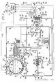
- FIG. 1 there is shown a refrigeration system 10 suitable for use with any conditioned space, and particularly well suited for use on straight trucks, tractor-trailer combinations, containers, and the like, with the word “vehicle” being used to generically refer to the various transport vehicles which utilize refrigeration systems.
- Refrigeration system 10 may be used in stationary and transport applications, with reference number 12 indicating a vehicle in a transport application, and simply an insulated wall in a stationary application. Refrigeration system 10 may be associated with a single conditioned space 14 to be controlled to a pre-selected set point temperature, and refrigeration system 10 may be associated with a compartmentalized application including two or more separate conditioned spaces 14 and 15 to be individually conditioned to selected set point temperatures.
- Conditioned space 15 will also be referred to as conditioned space and air conditioning apparatus 15, as reference 15 is used to generally refer both to a conditioned space and associated air conditioning apparatus, including a heat exchanger, for conditioning the space.
- Refrigeration system 10 includes cryogenic cooling means 13.
- Cryogenic cooling means 13 includes a vessel 16 containing a combustible fuel 17 in a cryogenic state, with a liquid and vapor phases thereof being respectively indicated at 18 and 20.
- fuel 17 is liquid natural gas (LNG), which is predominately methane (CH 4 ).
- LNG liquid natural gas
- CH 4 propane
- ethane C 2 H 6
- Vessel 16 may be filled, for example, by connecting a ground support apparatus, indicated generally at 22, to a supply line or conduit 24 which includes a valve 26.
- Vapor pressure in vessel 16 is maintained above a predetermined value by a pressure building and regulating arrangement 28 in which conduits 30 and 31 respectively connect pressure building means 33 to lower and upper points of vessel 16.
- Conduit 30, which connects a low point of vessel 16 to pressure building means 33 includes a valve 32.
- the pressure building means 33 includes a vaporizing coil 34, which may be directly exposed to ambient temperatures, or which may be disposed within a housing 35 for purposes which will be hereinafter explained.
- Valve 36 maintains the vapor pressure in vessel 16 at a predetermined level, which may be determined and selected each time vessel 16 is filled, if necessary.
- a pressure reading safety valve 38 is provided in conduit 31 at a point where the vapor pressure in vessel 16 may be directly sensed.
- a venting valve 40 is also provided to facilitate the filling process. Valve 40 may be connected to ground support apparatus 22 during filling, if desired.
- Valve 32 opens when the pressure in vessel 16 falls to a predetermined value, to enable the cryogen to flow into the pressure building arrangement 28.
- the predetermined value selected is based on factors such as optimum delivery system pressure and performance.
- valve 32 admits liquid cryogen into vaporizing coil 34, and vaporizing coil 34 is exposed to the ambient temperature outside of vehicle 12.
- heat produced during the normal operation of a refrigeration system may be used to enhance the vapor producing capabilities of ambient loops, such as vaporizing coil 34.
- vaporizing coil 34 may be exposed to higher temperatures than ambient, especially during low ambient temperature conditions, by utilizing gases produced as a product of combustion of vaporized fuel 20 during heating and defrost cycles; or, by utilizing a warmed liquid coolant associated with an internal combustion engine 41.
- internal combustion engine 41 is associated with vehicle 12, such as by being connected to a vehicle drive train 43 which propels vehicle 16, and thus refrigeration system 10 is illustrated in a transport application.
- engine 41 instead of being a vehicle drive engine, may be the prime mover for an electrical generator in a "gen-set" package utilized until the container is transported to a location which has a source of electrical potential.
- vessel 16 may be filled with LNG at an initial pressure of about (21 bars) (300 psia) and an initial temperature of about -160°F (-107°C), which will thermodynamically satisfy the low temperature end of the usual temperature control range of most refrigeration systems, including transport applications.
- initial pressure about (21 bars) (300 psia)
- initial temperature about -160°F (-107°C)
- other pressures and temperatures may be used than set forth in this example, as long as the temperature of the cryogen is low enough to thermodynamically maintain the desired set point temperature, or temperatures, in the associated conditioned space, or spaces.
- the present invention includes a fluid flow path 42, which will be called a "closed" fluid flow path as it is completely isolated from any direct contact with the cryogenic fuel 17, and from any direct contact with the air in conditioned space 14. Closed fluid flow path 42 may be at atmospheric pressure, or pressurized, as desired.
- the closed fluid flow path 42 includes a first portion 44 having a first heat exchanger 46.
- the first portion 44 extends between tees 48 and 50, with the first portion 44 including, from tee 48 to tee 50, a conduit 52, an optional position for a pump, referenced 54', as a preferred location is referenced 54, a conduit 56, a connector 58, a flow control valve 60, a conduit 62, the first heat exchanger 46, a conduit 64, a connector 66, a valve 67, a connector 68, a conduit 70, the preferred location for pump 54, and a conduit 75.
- the closed fluid flow path 42 includes second and third portions 74 and 76 which are connected in parallel with the first portion 44, each extending between tees 48 and 50.
- the second portion 74 includes a second heat exchanger 78.
- the second heat exchanger 78 is connected between tees 50 and 48 via a conduit 80 which includes a valve 82, and a conduit 84 which includes a valve 86.
- the second heat exchanger 78 is illustrated as being disposed within vessel 16, in direct heat exchange relation with cryogen 18, but as illustrated in Figures 2 and 3, the second heat exchanger 78 may be disposed in heat exchange relation with a wall 87 of vessel 16.
- the third portion 76 includes a third heat exchanger 88.
- the third heat exchanger 88 is connected between tees 50 and 48 via a conduit 90, and a conduit 92 which includes a valve 94.
- the second conditioned space and air conditioning apparatus 15, in a compartmentalized application, in a first embodiment thereof, is connected between connectors 66 and 68 via conduits 96 and 98, with one of the conduits, such as conduit 98, including a flow control valve 100.
- Valve 67 is closed when apparatus 15 is operational.
- apparatus 15 is connected in parallel with the first heat exchanger 46, instead of in series.
- connection to conduit 96 is made from connector 58 in conduit 56, instead of from connector 66 in conduit 64.
- Valve 67 may be replaced by a check valve in the second embodiment.
- An expansion and fill tank 102 for filling the closed fluid flow path 42 with a heat-exchange or secondary fluid 104, and also for allowing temperature induced expansion and contraction of the secondary fluid 104, is connected to connector 68.
- Tank 102 and the closed fluid flow path may be pressurized, depending upon the specific secondary fluid selected.
- the secondary fluid 104 should be a wide range liquid coolant selected to have good heat transfer and good transport properties while remaining in a liquid state throughout the different temperatures it will be subjected to. Examples of a suitable fluid for the secondary fluid include ethylene glycol and D-Limonene, with the latter being a trade name of Florida Chemical Co., Inc., Lake Alfred, Florida.
- the first heat exchanger 46 is associated with an air conditioning means or apparatus 108 which includes air mover means 110.
- Air mover means 110 includes a fan or blower 112 driven by a suitable motor 114.
- motor 114 is a vapor driven motor which is driven by vaporized cryogen 20 obtained from supply vessel 16 by arrangements which will be hereinafter explained.
- Air conditioning means 108 directs conditioned or discharge air, indicated by arrow 116, into conditioned space 14, via an opening 118 in a wall 120 of vehicle 12.
- the resulting conditioned air 116 is discharged back into conditioned space 14 via opening 118 and a discharge plenum which separates return air from discharge air.
- Electrical control 124 is provided for controlling the temperature of conditioned space 14 to a predetermined set point temperature which is selected by a set point selector 126. Electrical control 124 controls the temperature of conditioned space 14 via cooling and heating cycles, and electrical control 124 also initiates a defrost cycle to remove water ice build-up on heat exchanger 46, and a heat exchanger associated with apparatus 15, via a heating cycle. If it is desired that air mover means 110 remain operational during a defrost cycle, a controllable damper 128 is provided which closes opening 118 during defrost.
- Electrical control 124 receives inputs from a return air temperature sensor 130, a discharge air temperature sensor 132, a coil temperature sensor 134, an ambient air temperature sensor 136, and a pressure sensor associated with vessel 16, such as via the control line 135 from pressure reading valve 38.
- a set point temperature selector is also provided for each additional conditioned space, such as a set point temperature selector 138 for conditioned space 15.
- the additional conditioned space and associated air conditioning apparatus 15 may be constructed in the same manner as conditioned space 14 and the associated air conditioning means 108, and is thus not shown in detail.
- Fans or blowers in the additional conditioned spaces may be driven by electric, hydraulic, pneumatic, or vapor motors, as desired.
- the return air temperature, discharge air temperature, and ambient air temperature determine when electrical control 124 commands cooling and heating cycles, and the temperature of the coil surface of the first heat exchanger 46 detected by sensor 134 may be utilized to determine when a defrost cycle should be initiated.
- a defrost cycle may also be initiated by other means, such as by a timer, by a manually actuated switch, by a programmed algorithm, and the like.
- the second heat exchanger 78 is associated with cryogen cooling means 13, removing heat from the secondary fluid 104, and transferring the heat into the liquid cryogen 18.
- the second heat exchanger 78 may be constructed as illustrated in Figure 1, having a plurality of coil turns or loops 140 disposed within, and near the bottom of a metallic tank wall 87 of vessel 16. Thus, the turns or loops 140 of the heat exchanger are inside vessel 16, submerged in the liquid cryogen 18.
- Thermal insulation 144 surrounds inner tank 142, or a vacuum tank may be used.
- a suitable alternate construction arrangement for the second heat exchanger 78 is shown in Figures 2 and 3, with this alternate arrangement having a plurality of turns or loops 140' disposed in thermal contact with the outside surface of tank wall 87 of vessel 16, surrounded by thermal insulation 144.
- the third heat exchanger 88 includes a plurality of coil turns or loops 146 disposed within a suitable housing 147. Coil turns 146 are heated by heating means 148. Heating means 14 includes a burner 150. Vaporized fuel 20 from vessel 16, as will be hereinafter explained, is selectively directed to burner 150 via a conduit 152 and a valve 154. When electrical control 124 opens valve 154 to initiate the heating of coil turns 146 and the secondary fluid 104 therein, burner 150 is simultaneously ignited to provide a flame indicated at 156. In stationary applications, other suitable heat sources for heating the cryogen may be used, including electrical, hot liquids, and hot waste gases.
- Vaporized cryogen 20 for burner 150, as well as for operating vapor motor 114 and internal combustion engine 41 in the embodiment of Figure 1, independent of whether electrical control 124 is commanding cooling or heating cycles in the conditioned spaces 14 and 15, may be provided by tapping conduit 31.
- conduit 31 may be tapped via a tee 158, drawing vaporized cryogen 20 from vessel 16 and from the pressure building and regulating arrangement 28.
- An input side of vapor motor 114 is connected to tee 158 via a conduit 168, and an output side of vapor motor 114 is connected to the hereinbefore mentioned conduit 152.
- additional vaporized cryogen may be provided by an arrangement which includes tapping liquid conduit 30 with a tee 174, tapping conduit 168 with a tee 176, and connecting an ambient coil or loop 178 between tees 174 and 176 via a valve 180.
- valve 180 is opened by control 124, ambient loop 178 vaporizes liquid cryogen 18, adding to the available supply of vaporized cryogen.
- additional vaporized cryogen may be provided without requiring the addition of ambient loop 178, by using heat generated by refrigeration system 10 during normal operation thereof to enhance the heating of vaporizing coil 34.
- This arrangement is especially advantageous during low ambient temperatures.
- Drawing vaporized cryogen 20 from vessel 16 is also more desirable than drawing liquid cryogen 18 from vessel 16 via ambient loop 178 because the heat of vaporization removes heat from the liquid cryogen 18.
- hot gases produced by burner 150 may be directed from heater housing 147 to vaporizing housing 35 via a conduit 179 and a valve 181.
- warmed liquid coolant associated with internal combustion engine 41 may be directed in heat exchange relation with vaporizing coil 34.
- Ambient loop when provided, may be heated with by-product heat in the same manner as just described relative to vaporizing coil 34.
- Pump 54 may be driven by vapor motor 114, as illustrated in Figure 1 by a pulley-belt arrangement 182, or by an associated internal combustion engine, as will be hereinafter described relative to Figure 3. Pump 54 may also be driven by a motor, such as an electric, hydraulic or pneumatic motor. When an electric motor is used, a suitable source of electrical power for the motor will be hereinafter described relative to Figure 3.
- a motor such as an electric, hydraulic or pneumatic motor. When an electric motor is used, a suitable source of electrical power for the motor will be hereinafter described relative to Figure 3.
- internal combustion engine 41 is preferably operated using vaporized fuel 20 from the cryogenic means 13.
- engine 41 may utilize vaporized fuel after it has been expanded in vapor motor 114, with the expansion of the vaporized fuel driving vapor motor 114. If the vapor leaving vapor motor 114 is sufficiently cold, it may be passed through a separate path through heat exchanger 46, or the heat exchanger associated with apparatus 15, to gain an additional cooling benefit, before directing the vapor to internal combustion engine 41.
- Conduit 152 may be tapped with a tee 184, and tee 184 may be connected to engine 41 via a conduit 186 which includes a pressure regulating valve 188.
- Sufficient vaporized fuel 20 is assured by tapping conduits 168 and 186 with tees 190 and 192, respectively, and connecting a conduit 193 therebetween which includes a valve 194 and an expansion valve 195 which may have a fixed or a controlled orifice to provide approximately the same pressure drop as provided by vapor motor 114.
- Tees may be provided in fluid flow path portion 44, as disclosed in concurrently filed United States application Serial Nos. 07/982,370 and 07/982,548.
- refrigeration system 10 is associated with an application which requires both air conditioning and refrigeration, such as a transport application in which vehicle 12, in addition to conditioned space 14, includes a driver's cab to be air conditioned via the secondary fluid 104 while vehicle 16 is parked and occupied, making it unnecessary to operate the vehicle engine 41.
- the tees in fluid flow path portion 44 enable secondary fluid 104 to be selectively circulated through a heat exchanger associated with such a driver's cab.
- electrical control 124 When electrical control 124 detects the need for a cooling cycle in conditioned space 14 to maintain the set point temperature selected on set point selector 126, electrical control 124 energizes and thus opens valves 82 and 86, and electrical control 124 controls flow control valve 60 to control the flow rate of the secondary fluid 104 through the first heat exchanger 46. Cooled secondary fluid 104 is pumped from the second heat exchanger 78 to the first heat exchanger 46 via conduits 84, 52, 56, and 62.
- Heat in the return air 122 from conditioned space 14 is transferred to the secondary fluid 104, and the heated secondary fluid is pumped to the second heat exchanger 78 via conduits 64, 70, 75 and 80, where the heat is transferred into the liquid cryogen 18, and then removed therefrom by the heat of vaporization as liquid cryogen 18 vaporizes, providing vaporized cryogen 20 for the operation of vapor motor 114, burner 150, and internal combustion engine 41.
- a second conditioned space and air conditioning arrangement 15 When a second conditioned space and air conditioning arrangement 15 is provided in series with heat exchanger 46, and a cooling cycle is required in apparatus 15, flow control valve 100 is opened to allow secondary fluid in conduit 64 to circulate through the associated heat exchanger.
- the temperature of a second conditioned space associated with air conditioning apparatus 15 is selected via set point selector 138 to be a higher temperature conditioned space than conditioned space 14.
- conditioned space 14 may contain a frozen load, and the conditioned space indicated generally at 15 may contain a fresh load. If both conditioned spaces contain fresh loads, conditioned space 14 would be associated with the lower temperature load.
- valve 100 When apparatus 15 is connected in parallel with heat exchanger 46 via connector 58 and conduit 96', valve 100 is opened by electrical control 124 to allow secondary fluid in conduit 56 to circulate through the associated heat exchanger.
- apparatus 15 is not subject to the limitation of controlling to a higher temperature than conditioned space 14.
- valve 180 when ambient loop 178 is provided; or control 124 opens valve 181; or control 124 opens a valve shown in Figure 3 which allows warmed engine coolant to flow into heat exchange relation with vaporizing coil 34, when by-product heat is arranged to enhance the ability of pressure regulating coil 34 to produce vaporized cryogen.
- valves 82 and 86 When a heating cycle is required to hold the set point temperature in conditioned space 14, electrical control 124 closes valves 82 and 86, to completely isolate the second heat exchanger 78 from the secondary fluid flow path 44, valves 94 and 154 are opened, and burner 150 is ignited.
- the secondary fluid 104 is then pumped through the coil turns 146 of the third heat exchanger 88, with the heated secondary fluid 104 being directed to the first heat exchanger 46 via the now open valve 94 and conduits 52, 56 and 62.
- Secondary fluid 104 from heat exchanger 46 is directed back to the third heat exchanger 88 via conduits 64, 70, 75 and 90.
- a defrost cycle to defrost and remove water ice which may build up on the first heat exchanger 46 during a cooling cycle is similar to the heating cycle, except damper 128, when provided, is closed, to prevent warm air from being discharged into conditioned space 14; or, alternatively, valve 170 may be closed during a defrost cycle to stop vapor motor 114 from operating during a defrost cycle. Valve 194, if not already open, would be opened when valve 170 is closed to assure a flow of fuel to burner 150 and engine 41.
- valve 100 is controlled accordingly.
- conditioned space 14 is associated with a frozen load, a heating cycle is not required for space 14, and a controllable by-pass arrangement 204 may be provided to enable the first heat exchanger 46 to be by-passed in the first or series embodiment of apparatus 15.
- By-pass arrangement 204 includes a connector 58 in conduit 56, and a conduit 208 disposed between connector 58 and connector 66, with conduit 208 including a valve 210.
- By-pass arrangement 204 also permits electrical control 124 to select a null cycle, in addition to the heating and cooling cycles, when conditioned space 14 requires neither a heating cycle nor a cooling cycle to maintain the set point temperature.
- heat exchanger 46 requires defrosting and apparatus 15 requires a cooling cycle in the series embodiment of apparatus 15, heated fluid is passed through heat exchanger 46, by-passing apparatus 15 by closing valve 100 and opening valve 67. If apparatus 15 requires a defrost cycle while heat exchanger 46 requires a cooling cycle, valves 60 and 67 are closed and valves 210 and 100 are opened. In the parallel embodiment of apparatus 15, each parallel path is individually controlled as required to obtain the desired heating, cooling or defrost cycles in the associated conditioned spaces.
- electrical control 124 may independently serve the cooling, heating, and defrost requirements of conditioned spaces 14 and 15 by controlling valves 60, 67, 100, and 210.
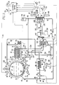
- FIG 2 is a diagrammatic representation of a refrigeration system 212 which is similar to refrigeration system 10 shown in Figure 1 except illustrating a thermosiphon arrangement for circulating the secondary fluid 104, eliminating the need for pump 54 of the Figure 1 embodiment.
- Like reference numerals in Figures 1 and 2 indicate like components and they are not described again relative to Figure 2.
- the thermosiphon arrangement of Figure 2 it is important that the second heat exchanger 78' be located at an elevation higher than the elevation of the first heat exchanger 46, and that the first heat exchanger 46 be located an elevation which is higher than the elevation of the third heat exchanger 88.
- the relative elevations of the first, second and third heat exchangers 46, 78 and 88 are respectively indicated at 214, 216 and 218.
- thermosiphon arrangement of Figure 2 during a cooling cycle, the secondary fluid leaving the first heat exchanger 46 will be warmer than the secondary fluid in the second heat exchanger 78, providing thermal gradients which move the warmer secondary fluid upward to the second heat exchanger 78, and the cooler secondary fluid downward from the second heat exchanger 78 to the first heat exchanger 46.
- Valve 94 will be closed to prevent circulation through heat exchanger 88.
- valves 82 and 86 will be closed and valve 94 will be open.
- the secondary fluid leaving the third heat exchanger 88 will be warmer than the secondary fluid in the first heat exchanger 46, providing thermal gradients which move the warmer secondary fluid upward to the first heat exchanger 46, and the cooler secondary fluid in the first heat exchanger 46 downward to the third heat exchanger 88.
- FIG. 2 also illustrates that a cooling water jacket 220 associated with internal combustion engine 41 may be provided and connected to a heat exchanger 222 which is disposed in heat exchange relation with vaporizing coil 34 of pressure building and vaporizing arrangement 28.
- Coolant conduits 224 and 226 circulate heated engine coolant from water jacket 220 through heat exchanger 222, via a flow control valve 228.
- a flooded design may be used wherein housing 35 contains the heated engine coolant in direct contact with coil 34.
- FIG. 3 is a diagrammatic representation of a refrigeration system 230 constructed according to another embodiment of the invention.
- a refrigeration system may have a small internal combustion engine 232 which is dedicated to providing mechanical and electrical power for the operation of pumps, fans, control, and the like, with the dedicated internal combustion engine 232 being operated via the cryogenic fuel 20.
- conduit 168 instead of being connected to vapor motor 114, is connected to a connector 234 via a pressure regulating valve 236.
- Connector 234 is connected to a first branch which includes a conduit 238 having a flow control valve 240, with the first branch providing a fuel supply for dedicated engine 232.
- Dedicated engine 232 drives an electrical generator or alternator 242, such as via a pulley-belt arrangement 244, and the electrical output of generator 242 is connected to an electrical circuit 246 which maintains a battery 248 in a fully charged condition. Electrical circuit 246 also provides electrical power for other purposes, such as for driving an electrical motor 250 connected to fan 112 of air mover means 110'.
- Engine 232 may drive pump 54, such as via a pulley-belt arrangement 252; or, pump 54 may be driven by an electrical motor connected to circuit 246, as desired.
- Connector 234 is connected to a second branch which includes the hereinbefore described heating means 148 via conductor 152.
- Connector 234 may be connected to a third branch 254 which is available for other apparatus which requires vaporized fuel, such as for a vehicle drive engine as described in the embodiments of Figures 1 and 2, or for an engine associated with a refrigerated container's gen-set.
- the associated internal combustion engine is started by electrical control 124, as indicated by control output conductor 256, at a pressure just below the release setting of valve 38.
- electrical control 124 senses the pressure level in vessel 16 via control input conductor 135. Starting the associated engine in response to pressure will reduce the pressure in vessel 16, and preclude the venting of unburned fuel.
- engine 232 is always under the supervision of electrical control 124, and engine 232 may be started and stopped whenever control 124 deems it necessary.
- electrical control 124 checks to determine if it is safe to start engine 41 before starting it for pressure control.
- Suitable sensors (not shown) provide inputs to electrical control 124, with electrical control making the decision on whether or not it is safe to start engine 41 based upon the sensor readings.
- Suitable sensors and logic circuitry for making the determination of whether it is safe to remotely start an engine which drives a vehicle are disclosed in U.S. Patent 5,072,703.
- the embodiments of the invention shown in Figures 2 and 3 may also utilize the multiple conditioned space arrangement of Figure 1. Further, the embodiment of the invention shown in Figure 3 may utilize the thermosiphon arrangement of Figure 2 by locating the second heat exchanger 78' at a higher elevation than the first heat exchanger 46, and by locating the first heat exchanger 46 at a higher elevation than the third heat exchanger 88.
- a pressure relief valve should be added at any location where cryogen may be trapped between two valves at shut down.
Claims (22)
- Système de réfrigération (10) associé à un espace climatisé (14) devant être régulé à une température prédéterminée de point de consigne (12) à l'aide de cycles de réchauffage et de refroidissement, le système comprenant :un moyen (13) de refroidissement cryogénique,ledit moyen de refroidissement cryogénique comprenant un carburant (18) dans un état cryogénique,un premier moyen formant échangeur de chaleur (46) en relation mutuelle de transfert de chaleur avec ledit espace climatisé,un deuxième moyen formant échangeur de chaleur (78) en relation mutuelle de transfert de chaleur avec ledit moyen de refroidissement cryogéniqueun moyen (74, 44) raccordant mutuellement lesdits premier et deuxième moyens formant échangeurs de chaleur de manière à produire un cycle de refroidissement,un moyen de réchauffage (148),un troisième moyen formant échangeur de chaleur (88) en relation mutuelle de transfert de chaleur avec ledit moyen de réchauffage,et un moyen (76, 44) raccordant mutuellement lesdits premier et troisième moyens formant échangeurs de chaleur de manière à produire un cycle de réchauffage,ledit moyen de réchauffage (148) comprenant un moyen (150) servant à utiliser un carburant provenant dudit moyen de refroidissement cryogénique pendant un cycle de réchauffage.
- Système de réfrigération selon la revendication 1, dans lequel le carburant cryogénique comprend une phase liquide (18), et comprenant:un moteur (41) à combustion interne,un moyen (28) de vaporisation de carburant liquide,et un moyen (168, 193, 186) faisant communiquer ledit carburant liquide vaporisé avec ledit moteur à combustion interne.
- Système de réfrigération selon la revendication 2, dans lequel le système de réfrigération est un système de réfrigération de moyen de transport, associé à un véhicule, le moteur à combustion interne étant associé au véhicule.
- Système de réfrigération selon la revendication 1, dans lequel le carburant cryogénique comprend une phase liquide (18), et comprenant:un moteur (41) à combustion interne,un moyen de circulation d'air (110) servant à faire circuler de l'air (122) entre l'espace climatisé (14) et le premier moyen formant échangeur de chaleur (46),ledit moyen de circulation d'air comprenant un moteur (114) à vapeur,un moyen (28) servant à vaporiser le carburant liquide,un moyen (168, 170) dirigeant le carburant vaporisé vers ledit moteur à vapeur, afin de faire fonctionner ledit moteur à vapeur par expansion dudit carburant vaporisé dans ce dernier,et une moyen (184, 186) dirigeant le carburant vaporisé depuis ledit moteur à vapeur vers ledit moteur à combustion interne pour faire fonctionner ledit moteur à combustion interne avec ledit carburant vaporisé expansé.
- Système de réfrigération selon la revendication 4, dans lequel le système de réfrigération est un système de réfrigération de moyen de transport associé à un véhicule, le moteur à combustion interne étant associé au véhicule.
- Système de réfrigération selon la revendication 1, dans lequel le moyen raccordant mutuellement les premier et deuxième moyens formant échangeurs de chaleur comprend :un circuit (42) d'écoulement de fluide, dans lequel se trouve un fluide secondaire prédéterminé (104)un moyen (54, 214, 216, 218) servant à faire circuler ledit fluide secondaire dans ledit circuit d'écoulement de fluide,et un moyen de commande (124) servant à commander ledit circuit d'écoulement de fluide de telle sorte que ledit fluide secondaire circule entre les premier et deuxième moyens formant échangeurs de chaleur pendant un cycle de refroidissement.
- Système de réfrigération selon la revendication 6, dans lequel le moyen de commande (124) commande le circuit (42) d'écoulement de fluide de telle sorte que le fluide secondaire (104) circule entre les premier et troisième moyens échangeurs de chaleur pendant un cycle de réchauffage.
- Système de réfrigération selon la revendication 6, Jans lequel le moyen servant à faire circuler le fluide (104) dans le circuit (42) d'écoulement de fluide comprend une pompe (54; 54').
- Système de réfrigération selon la revendication 8, dans lequel le carburant cryogénique comprend une phase liquide (18), et comprend:un moyen (110) de circulation d'air servant à faire circuler de l'air (122, 116) entre l'espace climatisé (14) et le premier moyen formant échangeur de chaleur (46),ledit moyen de circulation d'air comprenant un moteur à vapeur (114),un moyen (28) servant à vaporiser le carburant liquide,un moyen (168) dirigeant ledit carburant vaporisé vers ledit moteur à vapeur, afin de faire fonctionner ledit moteur à vapeur par expansion dudit carburant vaporisé dans ce dernier,et un moyen (182) raccordant fonctionnellement l'un à l'autre ledit moteur à vapeur et la pompe (54').
- Système de réfrigération selon la revendication 6, dans lequel le moyen servant à faire circuler le fluide dans le circuit d'écoulement de fluide comprend un agencement de thermosiphon (214, 216, 218) dans lequel le premier moyen formant échangeur de chaleur (46) est disposé à une hauteur plus faible que le deuxième moyen formant échangeur de chaleur (78).
- Système de réfrigération selon la revendication 7, dans lequel le moyen servant à faire circuler le fluide dans le circuit d'écoulement de fluide comprend un agencement de thermosiphon (214, 216, 218) dans lequel le premier moyen formant échangeur de chaleur (46) est disposé à une hauteur plus faible que le deuxième moyen formant échangeur de chaleur (78) et à une hauteur plus grande que le troisième moyen échangeur de chaleur (88).
- Système de réfrigération selon la revendication 1, dans lequel le carburant cryogénique comprend une phase liquide (18), et comprenant:un moteur (232) à combustion interne,un moyen (28) vaporisant le carburant liquide,un moyen (168) dirigeant le carburant vaporisé vers le moteur à combustion interne pour faire fonctionner ledit moteur à combustion interne avec ce carburant vaporisé ,un moyen formant générateur électrique (242) entaíné par ledit moteur à combustion interne,et un moyen de circulation d'air (110') servant à faire circuler de l'air entre l'espace climatisé et le premier moyen échangeur de chaleur,ledit moyen de circulation d'air comprenant un moteur électrique (250) alimenté par ledit moyen formant générateur électrique.
- Système de réfrigération selon la revendication 12, dans lequel le moyen qui raccorde mutuellement les premier et deuxième moyens formant échangeurs de chaleur comprend:un circuit (42) d'écoulement de fluide dans lequel se trouve un fluide secondaire prédéterminé (104),un moyen formant pompe (54) servant à faire circuler ledit fluide secondaire dans ledit circuit d'écoulement de fluide,et un moyen de commande (124) servant à commander le circuit d'écoulement de fluide de telle sorte que le fluide secondaire circule entre les premier et deuxième moyens formant échangeurs de chaleur pendant un cycle de refroidissement,ledit moyen formant pompe (54) étant entraíné (252) par le moteur à combustion interne.
- Système de réfrigération selon la revendication 1, dans lequel le carburant cryogénique comprend une phase liquide (18), et comprenant:un moteur (232) à combustion interne,un moyen (28) vaporisant le carburant liquide,un moyen (168) dirigeant le carburant vaporisé vers ledit moteur à combustion interne pour actionner ledit moteur à combustion interne avec le carburant vaporisé,un moyen formant générateur électrique (242) entraíné par ledit moteur à combustion interne,un moyen de circulation d'air (110') servant à faire circuler de l'air entre l'espace climatisé (14) et le premier moyen formant échangeur de chaleur (46),ledit moyen de circulation d'air comprenant un moteur électrique (250) alimenté par ledit moyen formant générateur électrique,et dans lequel le moyen de réchauffage (148) comprend un moyen formant brûleur (150) destiné à utiliser une partie du carburant vaporisé pour fournir de la chaleur pendant le cycle de réchauffage.
- Système de réfrigération selon la revendication 14, dans lequel le moyen qui raccorde mutuellement les premier et deuxième moyens formant échangeur de chaleur comprend:un circuit (42) d'écoulement de fluide contenant un fluide secondaire prédéterminé (104),un moyen formant pompe (54) servant à faire circuler ledit fluide secondaire dans ledit circuit d'écoulement de fluide,et un moyen de commande (124) pour commander l'écoulement de fluide de telle sorte que le fluide secondaire circule entre les premier et deuxième moyens formant échangeur de chaleur pendant un cycle de refroidissement,ledit moyen formant pompe étant entraíné (252) par le moteur à combustion interne.
- Système de réfrigération selon la revendication 15, dans lequel le fluide prédéterminé (104) est un liquide possédant la caractéristique de rester dans un état liquide pendant qu'il circule dans le circuit d'écoulement de fluide.
- Système de réfrigération selon la revendication 15, dans lequel le moyen de refroidissement cryogénique comprend un récipient d'alimentation (16) contenant le carburant dans l'état cryogénique qui comprend une phase liquide (18), le deuxième moyen formant échangeur de chaleur étant en relation mutuelle d'échange de chaleur avec ledit récipient d'alimentation.
- Système de réfrigération selon la revendication 1, comprenant un moyen (110) de circulation d'air qui fait circuler de l'air entre l'espace climatisé (14) et le premier moyen formant échangeur de chaleur (46), ledit moyen de circulation d'air comprenant un moteur (114) à vapeur, et dans lequel ledit moyen de refroidissement cryogénique comprend un récipient d'alimentation (16) contenant le carburant liquide (18) dans l'état cryogénique, et comprenant un moyen (28) d'accumulation de pression qui vaporise le cryogène liquide en provenance du récipient d'alimentation, le cryogène vaporisé maintenant une pression minimum prédéterminée dans le récipient d'alimentation et fournissant aussi un cryogène vaporisé qui se détend dans ledit moteur à vapeur.
- Système de réfrigération selon la revendication 18, comprenant un moteur (41) à combustion interne, ledit moteur à combustion interne étant actionné par le fluide cryogénique vaporisé expansé.
- Système de réfrigération selon la revendication 19, dans lequel le moteur à combustion interne comprend un liquide réfrigérant (220) qui est chauffé pendant le fonctionnement du moteur à combustion interne, et comprenant une moyen (224, 226, 228) amenant ledit liquide réfrigérant chauffé dans une disposition mutuelle d'échange de chaleur avec le moyen (28) d'accumulation de pression pour augmenter la transformation du cryogène liquide en cryogène vaporisé.
- Système de réfrigération selon la revendication 1, comprenant un moyen de circulation d'air (110) qui fait circuler de l'air (116, 122) entre l'espace climatisé (14) et le premier moyen formant échangeur de chaleur (46), ledit moyen de circulation d'air comprenant un moteur à vapeur (114), et dans lequel le moyen (13) de refroidissement cryogénique comprend un récipient d'alimentation (16) contenant le carburant liquide (18) dans l'état cryogénique qui comprend une phase liquide, et comprenant un moyen (28) servant à vaporiser le cryogène liquide, et un moyen (168) servant à diriger le cryogène vaporisé vers le moyen formant moteur à vapeur.
- Système de réfrigération selon la revendication 1, dans le quel le carburant cryogénique comprend une phase liquide (18) dans un récipient d'alimentation (16), et comprenant :un moteur (41; 232) à combustion interne, un moyen (28) vaporisant le carburant liquide,un moyen (168, 193, 186; 168, 238) faisant communiquer le carburant liquide vaporisé avec ledit moteur à combustion interne, un moyen (38, 135) détectant la pression régnant dans ledit récipient d'alimentation,et un moyen (124) servant à faire démarrer le moteur à combustion interne en réponse à des conditions prédéterminées, comprenant la pression dans ledit récipient d'alimentation.
Applications Claiming Priority (2)
| Application Number | Priority Date | Filing Date | Title |
|---|---|---|---|
| US07/982,368 US5259198A (en) | 1992-11-27 | 1992-11-27 | Air conditioning and refrigeration systems utilizing a cryogen |
| US982368 | 1992-11-27 |
Publications (3)
| Publication Number | Publication Date |
|---|---|
| EP0599611A2 EP0599611A2 (fr) | 1994-06-01 |
| EP0599611A3 EP0599611A3 (fr) | 1995-03-08 |
| EP0599611B1 true EP0599611B1 (fr) | 1998-04-08 |
Family
ID=25529101
Family Applications (1)
| Application Number | Title | Priority Date | Filing Date |
|---|---|---|---|
| EP93309347A Expired - Lifetime EP0599611B1 (fr) | 1992-11-27 | 1993-11-24 | Systèmes de conditionnement de l'air et de réfrigération sous utilisation d'un cryogène |
Country Status (6)
| Country | Link |
|---|---|
| US (1) | US5259198A (fr) |
| EP (1) | EP0599611B1 (fr) |
| JP (1) | JPH06241606A (fr) |
| CA (1) | CA2110101A1 (fr) |
| DE (1) | DE69317859T2 (fr) |
| MX (1) | MX9307295A (fr) |
Families Citing this family (40)
| Publication number | Priority date | Publication date | Assignee | Title |
|---|---|---|---|---|
| US5305825A (en) * | 1992-11-27 | 1994-04-26 | Thermo King Corporation | Air conditioning and refrigeration apparatus utilizing a cryogen |
| US5365744A (en) * | 1993-11-08 | 1994-11-22 | Thermo King Corporation | Air conditioning and refrigeration systems utilizing a cryogen |
| US5847246A (en) * | 1995-08-28 | 1998-12-08 | Daniel J. Loikits | Fluid heat transfer medium and heat transfer process |
| US5598709A (en) * | 1995-11-20 | 1997-02-04 | Thermo King Corporation | Apparatus and method for vaporizing a liquid cryogen and superheating the resulting vapor |
| US6086782A (en) * | 1996-07-02 | 2000-07-11 | Advanced Fluid Technologies, Inc. | Heat transfer fluid compositions for low temperature applications |
| US5904052A (en) * | 1996-09-02 | 1999-05-18 | Denso Corporation | Brine type air conditioning apparatus |
| EP0998645A4 (fr) * | 1997-07-11 | 2001-01-10 | Thermo King Corp | Procede de regulation pour unite cryogenique |
| US5916246A (en) * | 1997-10-23 | 1999-06-29 | Thermo King Corporation | System and method for transferring liquid carbon dioxide from a high pressure storage tank to a lower pressure transportable tank |
| US6272867B1 (en) | 1999-09-22 | 2001-08-14 | The Coca-Cola Company | Apparatus using stirling cooler system and methods of use |
| US6532749B2 (en) | 1999-09-22 | 2003-03-18 | The Coca-Cola Company | Stirling-based heating and cooling device |
| US6266963B1 (en) | 1999-10-05 | 2001-07-31 | The Coca-Cola Company | Apparatus using stirling cooler system and methods of use |
| US6862499B1 (en) | 2000-07-14 | 2005-03-01 | Thermo King Corporation | Environment-controlled transport unit |
| BG105182A (bg) * | 2001-01-25 | 2002-07-31 | МИТЕВ Ганчо | Система и метод за охлаждане на въздуха в превозни средства, използващи за гориво втечнен или сгъстен газ |
| US6581389B2 (en) | 2001-03-21 | 2003-06-24 | The Coca-Cola Company | Merchandiser using slide-out stirling refrigeration deck |
| US6550255B2 (en) | 2001-03-21 | 2003-04-22 | The Coca-Cola Company | Stirling refrigeration system with a thermosiphon heat exchanger |
| US6751966B2 (en) * | 2001-05-25 | 2004-06-22 | Thermo King Corporation | Hybrid temperature control system |
| DE10224724A1 (de) * | 2001-06-04 | 2003-01-30 | Thermo King Corp | Steuerverfahren für ein CRYO-Kühlsystem mit Eigenantrieb |
| US6698212B2 (en) * | 2001-07-03 | 2004-03-02 | Thermo King Corporation | Cryogenic temperature control apparatus and method |
| US6631621B2 (en) * | 2001-07-03 | 2003-10-14 | Thermo King Corporation | Cryogenic temperature control apparatus and method |
| US6647742B1 (en) * | 2002-05-29 | 2003-11-18 | Carrier Corporation | Expander driven motor for auxiliary machinery |
| US6694765B1 (en) * | 2002-07-30 | 2004-02-24 | Thermo King Corporation | Method and apparatus for moving air through a heat exchanger |
| US7434407B2 (en) * | 2003-04-09 | 2008-10-14 | Sierra Lobo, Inc. | No-vent liquid hydrogen storage and delivery system |
| US6895764B2 (en) * | 2003-05-02 | 2005-05-24 | Thermo King Corporation | Environmentally friendly method and apparatus for cooling a temperature controlled space |
| US6925821B2 (en) * | 2003-12-02 | 2005-08-09 | Carrier Corporation | Method for extracting carbon dioxide for use as a refrigerant in a vapor compression system |
| EP2013557A4 (fr) * | 2006-05-01 | 2010-09-01 | Thermo King Corp | Système de régulation de la température et procédé de mise en oeuvre associé |
| JP4779928B2 (ja) * | 2006-10-27 | 2011-09-28 | 株式会社デンソー | エジェクタ式冷凍サイクル |
| WO2008079875A1 (fr) * | 2006-12-21 | 2008-07-03 | Thermo King Corporation | Système de chauffage pour unité de réfrigération de transport |
| US20090248218A1 (en) * | 2008-03-28 | 2009-10-01 | Thermo King Corporation | Environment control system for a transport unit |
| FR2934018B1 (fr) * | 2008-07-18 | 2010-08-20 | Valeo Systemes Thermiques | Dispositif de commande d'un compresseur a capacite fixe |
| DK2545331T3 (da) | 2010-03-08 | 2017-11-27 | Carrier Corp | Afrimning og anordning til et transportkølesystem |
| US9759462B2 (en) * | 2010-07-23 | 2017-09-12 | Carrier Corporation | High efficiency ejector cycle |
| DE102011008278A1 (de) * | 2011-01-11 | 2012-07-12 | Thilo Rießner | Verfahren und Vorrichtung zur Gebäudeklimatisierung |
| CN102198783B (zh) * | 2011-04-11 | 2012-09-26 | 上海理工大学 | 一种利用液化天然气冷量的汽车空调系统 |
| KR101836514B1 (ko) * | 2012-07-11 | 2018-04-19 | 현대자동차주식회사 | 차량용 공조장치 |
| CN103712056B (zh) * | 2012-10-02 | 2017-11-14 | 查特股份有限公司 | 具有主动式增压能力的深冷液体输送及增压系统和方法 |
| US20140138045A1 (en) * | 2012-11-21 | 2014-05-22 | Clean Vehicle Solutions Llc | Compressed natural gas refrigerated vehicle and regulator therefor |
| ES2510290B2 (es) * | 2013-03-20 | 2015-04-30 | Emilio PALOMO PINTO | Sistema de refrigeración autónomo, portátil y autorefrigerante, basado en la utilización de un depósito estanco, conteniente de un gas licuado a presión, empleado como vaporizador, como consecuencia de la evaporación controlada de dicho GLP |
| ES2662133T3 (es) * | 2014-11-14 | 2018-04-05 | Milestone S.R.L. | Método y aparato para la crioconservación de especímenes biológicos |
| US11015855B2 (en) * | 2015-02-27 | 2021-05-25 | Daikin Industries, Ltd. | Refrigeration apparatus for containers |
| US10941713B2 (en) | 2016-05-27 | 2021-03-09 | Carrier Corporation | Multi-fuel transport refrigeration unit |
Family Cites Families (18)
| Publication number | Priority date | Publication date | Assignee | Title |
|---|---|---|---|---|
| US2535364A (en) * | 1946-07-26 | 1950-12-26 | Maurice W Lee | Liquefied gas storage system |
| US3802212A (en) * | 1972-05-05 | 1974-04-09 | Gen Cryogenics | Refrigeration apparatus |
| US3740961A (en) * | 1972-05-22 | 1973-06-26 | Allied Chem | Open cycle ammonia refrigeration system |
| US3823568A (en) * | 1973-08-29 | 1974-07-16 | T Bijasiewicz | Method and apparatus for air conditioning vehicles |
| US4030313A (en) * | 1976-04-09 | 1977-06-21 | Patrick Ernest H | Air conditioner |
| US4045972A (en) * | 1976-07-23 | 1977-09-06 | Lewis Tyree Jr | CO2 Cooling of vehicles |
| US4186562A (en) * | 1976-11-01 | 1980-02-05 | Lewis Tyree Jr | Cryogenic refrigeration for vehicles |
| US4100759A (en) * | 1976-11-01 | 1978-07-18 | Lewis Tyree Jr | CO2 vehicle refrigeration support systems |
| DE3047023A1 (de) * | 1980-12-13 | 1982-07-22 | Daimler-Benz Ag, 7000 Stuttgart | Verfahren zum kuehlen von innenraeumen von fahrzeugen mit wasserstoff verbrauchenden kraftmaschinen nach dem kompressionskaelteverfahren |
| US4406129A (en) * | 1981-12-11 | 1983-09-27 | Beech Aircraft Corporation | Saturated cryogenic fuel system |
| US4498306A (en) * | 1982-11-09 | 1985-02-12 | Lewis Tyree Jr | Refrigerated transport |
| DE3344770C2 (de) * | 1983-12-10 | 1986-01-02 | Deutsche Forschungs- und Versuchsanstalt für Luft- und Raumfahrt e.V., 5300 Bonn | Verfahren und Vorrichtung zur automatischen Betankung eines Flüssigwasserstofftanks in einem Kraftfahrzeug |
| SE464529B (sv) * | 1988-10-31 | 1991-05-06 | Gunnar Haeggstroem | Drivanordning foer motorfordon, saerskilt bussar |
| FR2641854B1 (fr) * | 1988-12-28 | 1994-01-14 | Carboxyque Francaise | Procede et dispositif de regulation d'un debit de co2 liquide, et application a un tunnel de refroidissement |
| US5069039A (en) * | 1990-10-01 | 1991-12-03 | General Cryogenics Incorporated | Carbon dioxide refrigeration system |
| US5090209A (en) * | 1990-10-01 | 1992-02-25 | General Cryogenics Incorporated | Enthalpy control for co2 refrigeration system |
| US5072703A (en) * | 1990-10-16 | 1991-12-17 | Thermo King Corporation | Apparatus for the automatic starting running, and stopping of an internal combustion engine |
| US5127230A (en) * | 1991-05-17 | 1992-07-07 | Minnesota Valley Engineering, Inc. | LNG delivery system for gas powered vehicles |
-
1992
- 1992-11-27 US US07/982,368 patent/US5259198A/en not_active Expired - Fee Related
-
1993
- 1993-11-23 MX MX9307295A patent/MX9307295A/es unknown
- 1993-11-24 EP EP93309347A patent/EP0599611B1/fr not_active Expired - Lifetime
- 1993-11-24 DE DE69317859T patent/DE69317859T2/de not_active Expired - Fee Related
- 1993-11-26 CA CA002110101A patent/CA2110101A1/fr not_active Abandoned
- 1993-11-29 JP JP5325877A patent/JPH06241606A/ja not_active Withdrawn
Also Published As
| Publication number | Publication date |
|---|---|
| DE69317859D1 (de) | 1998-05-14 |
| JPH06241606A (ja) | 1994-09-02 |
| EP0599611A2 (fr) | 1994-06-01 |
| US5259198A (en) | 1993-11-09 |
| EP0599611A3 (fr) | 1995-03-08 |
| DE69317859T2 (de) | 1998-10-22 |
| MX9307295A (es) | 1994-05-31 |
| CA2110101A1 (fr) | 1994-05-28 |
Similar Documents
| Publication | Publication Date | Title |
|---|---|---|
| EP0599611B1 (fr) | Systèmes de conditionnement de l'air et de réfrigération sous utilisation d'un cryogène | |
| US5305825A (en) | Air conditioning and refrigeration apparatus utilizing a cryogen | |
| EP0599612B1 (fr) | Appareil de conditionnement de l'air et de réfrigération sous utilisation d'un cryogène | |
| EP0599625B1 (fr) | Systèmes de conditionnement de l'air et de réfrigération sous utilisation d'un cryogène et de tubes de chauffe | |
| US5267443A (en) | Air conditioning and refrigeration methods and apparatus utilizing a cryogen | |
| EP0599610B1 (fr) | Procédé et appareil de conditionnement de l'air et de réfrigération sous utilisation d'un cryogène | |
| US6698212B2 (en) | Cryogenic temperature control apparatus and method | |
| EP0611934B1 (fr) | Systèmes de conditionnement d'air et de réfrigération utilisant un cryogène | |
| US5730216A (en) | Air conditioning and refrigeration units utilizing a cryogen | |
| US20020129613A1 (en) | Cryogenic refrigeration unit suited for delivery vehicles | |
| US6694765B1 (en) | Method and apparatus for moving air through a heat exchanger | |
| EP0599627B1 (fr) | Méthode de contrÔle de la température d'un espace climatisé utilisant un cryogène | |
| WO2009134549A1 (fr) | Système de réfrigération cryogénique à boucle fermée et ouverte | |
| EP0599639B1 (fr) | Dispositif et méthode de conditionnement d'air utilisant un cryogène | |
| CA2108190A1 (fr) | Systeme de controle de la temperature au co2, pour vehicules de transport |
Legal Events
| Date | Code | Title | Description |
|---|---|---|---|
| PUAI | Public reference made under article 153(3) epc to a published international application that has entered the european phase |
Free format text: ORIGINAL CODE: 0009012 |
|
| AK | Designated contracting states |
Kind code of ref document: A2 Designated state(s): DE FR GB IT |
|
| PUAL | Search report despatched |
Free format text: ORIGINAL CODE: 0009013 |
|
| AK | Designated contracting states |
Kind code of ref document: A3 Designated state(s): DE FR GB IT |
|
| RHK1 | Main classification (correction) |
Ipc: F25B 19/00 |
|
| 17P | Request for examination filed |
Effective date: 19951127 |
|
| 17Q | First examination report despatched |
Effective date: 19961016 |
|
| GRAG | Despatch of communication of intention to grant |
Free format text: ORIGINAL CODE: EPIDOS AGRA |
|
| GRAG | Despatch of communication of intention to grant |
Free format text: ORIGINAL CODE: EPIDOS AGRA |
|
| GRAH | Despatch of communication of intention to grant a patent |
Free format text: ORIGINAL CODE: EPIDOS IGRA |
|
| GRAH | Despatch of communication of intention to grant a patent |
Free format text: ORIGINAL CODE: EPIDOS IGRA |
|
| GRAA | (expected) grant |
Free format text: ORIGINAL CODE: 0009210 |
|
| AK | Designated contracting states |
Kind code of ref document: B1 Designated state(s): DE FR GB IT |
|
| PG25 | Lapsed in a contracting state [announced via postgrant information from national office to epo] |
Ref country code: IT Free format text: LAPSE BECAUSE OF FAILURE TO SUBMIT A TRANSLATION OF THE DESCRIPTION OR TO PAY THE FEE WITHIN THE PRESCRIBED TIME-LIMIT;WARNING: LAPSES OF ITALIAN PATENTS WITH EFFECTIVE DATE BEFORE 2007 MAY HAVE OCCURRED AT ANY TIME BEFORE 2007. THE CORRECT EFFECTIVE DATE MAY BE DIFFERENT FROM THE ONE RECORDED. Effective date: 19980408 |
|
| ET | Fr: translation filed | ||
| REF | Corresponds to: |
Ref document number: 69317859 Country of ref document: DE Date of ref document: 19980514 |
|
| PLBE | No opposition filed within time limit |
Free format text: ORIGINAL CODE: 0009261 |
|
| STAA | Information on the status of an ep patent application or granted ep patent |
Free format text: STATUS: NO OPPOSITION FILED WITHIN TIME LIMIT |
|
| 26N | No opposition filed | ||
| REG | Reference to a national code |
Ref country code: GB Ref legal event code: IF02 |
|
| PGFP | Annual fee paid to national office [announced via postgrant information from national office to epo] |
Ref country code: FR Payment date: 20021030 Year of fee payment: 10 |
|
| PGFP | Annual fee paid to national office [announced via postgrant information from national office to epo] |
Ref country code: GB Payment date: 20021120 Year of fee payment: 10 |
|
| PGFP | Annual fee paid to national office [announced via postgrant information from national office to epo] |
Ref country code: DE Payment date: 20021202 Year of fee payment: 10 |
|
| PG25 | Lapsed in a contracting state [announced via postgrant information from national office to epo] |
Ref country code: GB Free format text: LAPSE BECAUSE OF NON-PAYMENT OF DUE FEES Effective date: 20031124 |
|
| PG25 | Lapsed in a contracting state [announced via postgrant information from national office to epo] |
Ref country code: DE Free format text: LAPSE BECAUSE OF NON-PAYMENT OF DUE FEES Effective date: 20040602 |
|
| GBPC | Gb: european patent ceased through non-payment of renewal fee |
Effective date: 20031124 |
|
| PG25 | Lapsed in a contracting state [announced via postgrant information from national office to epo] |
Ref country code: FR Free format text: LAPSE BECAUSE OF NON-PAYMENT OF DUE FEES Effective date: 20040730 |
|
| REG | Reference to a national code |
Ref country code: FR Ref legal event code: ST |