EP0599330A1 - RDS-Rundfunkempfänger - Google Patents
RDS-Rundfunkempfänger Download PDFInfo
- Publication number
- EP0599330A1 EP0599330A1 EP93119058A EP93119058A EP0599330A1 EP 0599330 A1 EP0599330 A1 EP 0599330A1 EP 93119058 A EP93119058 A EP 93119058A EP 93119058 A EP93119058 A EP 93119058A EP 0599330 A1 EP0599330 A1 EP 0599330A1
- Authority
- EP
- European Patent Office
- Prior art keywords
- radio station
- broadcast signal
- signal
- rds
- data
- Prior art date
- Legal status (The legal status is an assumption and is not a legal conclusion. Google has not performed a legal analysis and makes no representation as to the accuracy of the status listed.)
- Granted
Links
Images


Classifications
-
- H—ELECTRICITY
- H04—ELECTRIC COMMUNICATION TECHNIQUE
- H04H—BROADCAST COMMUNICATION
- H04H20/00—Arrangements for broadcast or for distribution combined with broadcast
- H04H20/20—Arrangements for broadcast or distribution of identical information via plural systems
- H04H20/22—Arrangements for broadcast of identical information via plural broadcast systems
-
- H—ELECTRICITY
- H04—ELECTRIC COMMUNICATION TECHNIQUE
- H04H—BROADCAST COMMUNICATION
- H04H40/00—Arrangements specially adapted for receiving broadcast information
- H04H40/18—Arrangements characterised by circuits or components specially adapted for receiving
-
- H—ELECTRICITY
- H04—ELECTRIC COMMUNICATION TECHNIQUE
- H04H—BROADCAST COMMUNICATION
- H04H2201/00—Aspects of broadcast communication
- H04H2201/10—Aspects of broadcast communication characterised by the type of broadcast system
- H04H2201/13—Aspects of broadcast communication characterised by the type of broadcast system radio data system/radio broadcast data system [RDS/RBDS]
Definitions
- This invention relates to an RDS (radio data system) receiver.
- the RDS receivers have been widely used for instance in Europe.
- the RDS receiver has an AF (alternative frequency) switching function; that is, when is being moved, it is able to receive one and the same program continuously while switching the receiving frequencies.
- AF alternative frequency
- RDS data transmitted from radio stations, being modulated in a multiplex mode include data on an AF list which is a list of different frequencies with which one and the same program is broadcasted.
- the RDS receiver momentarily receives the broadcast signal of an aimed one of the frequencies registered in the AF list, and detects its field strength with a signal strength meter (hereinafter referred to as "an S meter", when applicable).
- an S meter a signal strength meter
- the S meter is wide in receiving signal band. Therefore, the RDS receiver is disadvantageous in the following points: If interference of adjacent frequency signals occurs while the signal of a frequency is being received which is low in field strength, then it may be erroneously determined to be high in field strength by the effect of the interference, as a result of which a frequency switching operation is carried out to select the signal.
- Japanese Patent Unexamined Publication No. Hei. 1-208030 has disclosed the following method: The broadcast signal of a radio station of which the frequency is registered in the AF code list (hereinafter referred to as "a first radio station", when applicable), and the broadcast signal of another radio station (hereinafter referred to as "a second radio station", when applicable) of which the frequency is within ⁇ 100 kHz of the broadcasting frequency of the first radio station are received, and the field strength of the broadcast signal of the first radio station is adjusted according to the field strength of the broadcast signal of the second radio station.
- the method it is necessary to receive the broadcast signal of the second radio station of which the frequency is close to that of the broadcast signal of the first radio station which is registered in the AF code list.
- the method is disadvantageous in that selection of a radio station takes time; that is, the RDS device is low in response.
- an object of this invention is to eliminate the above-described difficulties accompanying a conventional RDS receiver.
- the invention provides an RDS receiver which automatically selects the highest one in broadcast signal field strength of a plurality of radio stations broadcasting one and the same program according to AF codes corresponding to the radio stations included in transmission data in a radio data system, including receiving means for receiving the transmission data, automatic tuning means for automatically selecting one from among the plurality of radio stations broadcasting one and the same program according to the AF codes included in the transmission data which are received by the receiving means, interference detecting means for detecting whether or not the broadcast signal of an AF code radio station being received suffers from adjacent frequency interference before the automatic selecting operation by the automatic tuning means, and decreasing means for decreasing a value of data on the field strength of the broadcast signal of the AF code radio station when the interference detecting means detects that the broadcast signal of the AF code radio station suffers from adjacent frequency interference.
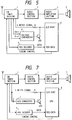
- FIG. 1 is a block diagram showing an RDS receiver according to a first embodiment of the invention.
- An RDS broadcast signal received by an FM tuner section 1 is applied through an audio control section 2 and an audio amplifier section 3 to a loudspeaker S, where it is reproduced as sounds.
- the field strength of the broadcast signal received by the FM tuner section 1 is applied as an S meter signal to a CPU (central processing unit) 4, in which it is subjected to digital conversion. Thus, the field strength of the broadcast signal is detected.
- RDS data received by the FM tuner section 1 are decoded by an RDS decoder 5, and applied to the CPU 4. At this time, an RDS flag is outputted from the RDS decoder 5, to allow the CPU 4 to confirm that the RDS data are available.
- the CPU 4 performs an AF switching operation according to a predetermined program. That is, according to an AF list included in the RDS data, the broadcasting frequencies are switched to select a radio station broadcasting the same program with a higher field strength.
- the embodiment is so designed that the AF switching operation is carried out correctly even if interference of adjacent frequency signals occurs.
- RDS data can be obtained when the field strength is of the order of about 15 to 30 dB.
- the sensitivity is decreased because of the AGC characteristic of the tuner, and the RDS data obtaining capability is lowered.
- the CPU 4 determines it from the RDS flag supplied from the RDS decoder 5 whether or not the RDS data have been obtained, and detects whether or not the S meter signal is larger than the true value V a of field strength with which RDS data can be obtained.
- the S meter signal is larger than the true value V a , it can be determined that there is an interfering radio station. Therefore, in this case, the value indicated by the S meter signal is forcibly regarded as zero, and the above-described AF switching operation is carried out.
- the previous broadcast signal may be received again which suffers from the interfering signal. That is, the field strength comparison must be achieved instantaneously when the frequencies are switched, and it is difficult to determine whether or not RDS data can be obtained in a short time. Therefore, the above-described decision with the S meter signal is rather difficult to achieve, so that the signal reception may be switched back.
- the CPU 4 marks the frequency of the radio station in the AF list, and lowers the order of priority in switching the receiving frequency over to the frequency of the radio station.
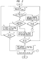
- An RDS broadcast signal is received (Step 10), and it is determined whether or not RDS data are available (Step 11).
- RDS data are available
- broadcast signals from radio stations registered in the AF list are successively received; that is, the frequency switching operation is carried out according to the AF list (Step 12).
- the broadcast signal of the better radio station is selected (Step 20).
- Step 10 is effected again.
- Step 14 current voltage value of the S meter signal is compared with the voltage value V a of the S meter signal when the field strength is high enough to obtain RDS data (Step 14).
- the voltage value of the S meter signal is equal to or smaller than V a , it is determined that the voltage value of the S meter signal is correct, and the switching operation is carried out (Step 15), and it is detected whether or not there is a radio station higher than the receiving station in field strength (Step 16).
- Step 10 is effected again.
- Step 20 is effected; that is, the better radio station is selected.
- Step 14 When, in Step 14, the voltage value of the S meter signal is larger than V a , the voltage value is forcibly regarded as zero (0), and the switching operation is carried out (Step 17).
- Step 18 When there is a better radio station broadcasting the same program with a higher field strength (Step 18), the frequency of the receiving radio station in the AF list is marked, and the order of priority in switching the receiving frequency over to it is lowered (Step 19), and the broadcast signal of the better radio station higher in field strength is selected (Step 20).
- Step 10 is effected again.
- the AF switching operation is carried out according to the signal receiving conditions, not only the field strength but also the degree of signal interference.
- the broadcast signal can be accurately switched over to that of a radio station higher than the receiving station in field strength.
- the frequency of the radio station which has been interfered is marked, and the order of priority in switching the receiving frequency over to it is lowered.
- This method eliminates the difficulty that the radio station which has been interfered is selected again.
- the RDS receiver is high in response, and needs not to have a large capacity memory.
- FIG. 3 shows the arrangement of an RDS receiver according to the second embodiment of the invention. In the second embodiment, it is detected whether or not RDS data are obtained, thereby to detect interference of adjacent frequency signals.
- the RDS is a broadcasting system in which pulse modulation signals are superposed on an FM modulation signal in a multiplex mode by using a pilot signal of 57 kHz. Since the pilot signal is of high tone, 57 kHz, the demodulation frequency band must be sufficiently wide. In general, the filter characteristic of a demodulation band is proportional to the magnitude of signal strength; that is, it is wide with a high signal strength, and narrow with a low signal strength. Hence, the RDS data cannot be demodulated when the signal strength decreases to some extent. In the case of interference of adjacent frequency signals, or in the case where interference occurs with the receiving frequency, the sensitivity is decreased by AGC (automatic gain control), and therefore the signal strength can be lowered.
- AGC automatic gain control
- An RDS broadcast signal received by an FM tuner section 1 is applied through an audio control section 2 and an audio amplifier section 3 to a loudspeaker S, where it is reproduced as sounds.
- the field strength of the broadcast signal received by the FM tuner section 1 is applied as an S meter signal to a CPU 4, in which it is subjected to digital conversion. Thus, the field strength of the broadcast signal is detected.
- RDS data received by the FM tuner section 1 are decoded by an RDS decoder 5, and applied to the CPU 4.
- the RDS decoder 5 sets an RDS flag, and applies an RDS presence or absence signal to a transistor Q, so that the transistor Q is rendered conductive (on) when no RDS data is detected.
- the S meter signal is grounded; whereas when the transistor Q is rendered non-conductive (off), the S meter signal is not grounded. That is, when no RDS data is detected, the S meter signal is decreased.
- the CPU 4 performs an AF switching operation according to a predetermined program. That is, according to an AF list included in the RDS data, the broadcasting frequencies are switched to select a radio station broadcasting the same program with a higher field strength.
- Step 21 An RDS broadcast signal is received (Step 21), and it is determined whether or not RDS data are available (Step 22A).
- RDS data broadcast signals from radio stations registered in the AF list are successively received; that is, the frequency switching operation is carried out according to the AF list (Step 23).
- Step 24 When there is a better radio station which broadcasts the same program with a field strength higher than that of the receiving station (Step 24), then the broadcast signal of the better radio station is selected (Step 28). When there is no such a better radio station, then Step 21 is effected again.
- Step 25 the voltage value of the S meter signal is forcibly zeroed by rendering the transistor Q conductive, and the switching operation is carried out (Step 25).
- Step 26 the frequency of the receiving radio station in the AF list is marked, and the order of priority in switching the receiving frequency over to it is lowered (Step 27), and the broadcast signal of the better radio station higher in field strength is selected (Step 28).
- Step 21 is effected again.
- the S meter signal may be increased for instance when interference of adjacent frequency signals occurs. If, in this case, it is determined from the non-detection of RDS data that there is interference of adjacent frequency signals, the transistor Q is rendered conductive (on), so that the S meter signal is forcibly zeroed. Thus, the radio stations are correctly traced. Further, unlike the conventional receiver, it is unnecessary to receive the broadcast signal of a radio station whose frequency is adjacent to the frequencies registered in the AF code list. Therefore, the RDS receiver is high in response, and needs not to have a large capacity memory.
- FIG. 5 shows a third embodiment of the invention which detects interference of adjacent frequency signals on the basis of AFC (automatic frequency control).
- a stable tuning frequency can be detected with respect to a received frequency by AFC.
- frequency deviation of ⁇ 75 kHz from a received frequency occurs; however, the central frequency and the received frequency are made coincident with each other by AFC all the time.
- the frequency deviation thereof affects the receiving frequency, so that the receiving frequency becomes non-uniform in frequency deviation.
- the frequency regarded as the central frequency is shifted by AFC, and the voltage output of AFC is varied.
- the interfering radio station can be detected by detection of the variation in the voltage output of AFC.
- the FM tuner section 1 applies an AFC voltage V AFC and a reference voltage V ref to a voltage comparator 6, where they are subjected to comparison. When the difference between those voltages is higher than a predetermined value a , the voltage comparator 6 outputs an interfering radio station detection signal, which is applied to the transistor Q. When the transistor Q is rendered conductive (on) by the detection signal, the S meter signal from the FM tuner section 1 is forcibly zeroed.
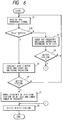
- FIG. 6 is a flow chart for explaining the operation of the RDS receiver shown in FIG. 5.
- Step 22B it is determined whether or not
- the other Steps are the same as those in FIG. 4 which have been described, and the explanation thereof will be omitted.
- the S meter signal may be increased for instance when interference of adjacent frequency signals occurs. If, in this case, it is determined from the variation in the output voltage of AFC that there is interference of adjacent frequency signals, the transistor Q is rendered conductive (on), so that the S meter signal is forcibly zeroed. Thus, with the RDS receiver, the radio station tracing operation is carried out correctly. Also, in this embodiment, unlike the conventional receiver, it is unnecessary to receive the broadcast signal of a radio station whose frequency is adjacent to the frequencies registered in the AF code list. Therefore, the RDS receiver is high in response, and needs not to have a large capacity memory.
- FIG. 7 shows a fourth embodiment of the invention in which an AC component of the S meter signal is utilized to detect interference of adjacent frequency signals.
- the S meter signal outputted from the FM tuner section 1 is applied to a capacitor C, so that its AC component is extracted.
- the AC component is applied to an A/D (analog-to-digital) converter 7, where it is subjected to analog-to-digital conversion.
- the output of the converter 7 is applied to the transistor Q to render the latter Q conductive (on).
- the transistor Q is rendered conductive (on)
- the S meter signal is zeroed.
- the interfering radio station can be detected.
- FIG. 8 is a flow chart for explaining the operation of the RDS receiver shown in FIG. 7.
- Step 22C it is determined whether or not the AC component of the S meter signal is larger.
- Step 22C it is determined whether or not the AC component of the S meter signal is larger.
- the S meter signal may be increased for instance when interference of adjacent frequency signals occurs. If, in this case, the presence of interference of adjacent frequency signals is determined from the detection of the AC component of the S meter signal, then the transistor Q is rendered conductive (on), so that the S meter signal is forcibly zeroed.
- the radio station tracing operation is carried out correctly. Also, in this embodiment, unlike the conventional receiver, it is unnecessary to receive the broadcast signal of a radio station whose frequency is adjacent to the frequencies registered in the AF code list. Therefore, the RDS receiver is high in response, and needs not to have a large capacity memory.
Landscapes
- Engineering & Computer Science (AREA)
- Signal Processing (AREA)
- Circuits Of Receivers In General (AREA)
- Channel Selection Circuits, Automatic Tuning Circuits (AREA)
- Noise Elimination (AREA)
Applications Claiming Priority (4)
| Application Number | Priority Date | Filing Date | Title |
|---|---|---|---|
| JP341173/92 | 1992-11-27 | ||
| JP4341173A JP3017896B2 (ja) | 1992-11-27 | 1992-11-27 | 多重放送受信機 |
| JP4737693A JPH06244751A (ja) | 1993-02-12 | 1993-02-12 | Rds受信機 |
| JP47376/93 | 1993-02-12 |
Publications (2)
| Publication Number | Publication Date |
|---|---|
| EP0599330A1 true EP0599330A1 (de) | 1994-06-01 |
| EP0599330B1 EP0599330B1 (de) | 1996-06-26 |
Family
ID=26387537
Family Applications (1)
| Application Number | Title | Priority Date | Filing Date |
|---|---|---|---|
| EP19930119058 Revoked EP0599330B1 (de) | 1992-11-27 | 1993-11-25 | RDS-Rundfunkempfänger |
Country Status (2)
| Country | Link |
|---|---|
| EP (1) | EP0599330B1 (de) |
| DE (1) | DE69303348T2 (de) |
Cited By (2)
| Publication number | Priority date | Publication date | Assignee | Title |
|---|---|---|---|---|
| EP0905929A3 (de) * | 1997-09-26 | 2000-05-17 | Robert Bosch Gmbh | Verfahren zur schnellen optimalen Auswahl der alternativen Frequenzen in einem Radiodatenempfänger |
| GB2392349A (en) * | 2002-08-21 | 2004-02-25 | Lear Corp | Remote access transmitter and receiver for vehicles |
Citations (4)
| Publication number | Priority date | Publication date | Assignee | Title |
|---|---|---|---|---|
| EP0275527A1 (de) * | 1986-12-19 | 1988-07-27 | TELEFUNKEN Fernseh und Rundfunk GmbH | Verfahren zum Übertragen und/oder zum empfangsseitigen Auswerten zusätzlicher Informationen innerhalb eines Rundfunksignals |
| WO1988008223A1 (en) * | 1987-04-15 | 1988-10-20 | H.U.C. Elektronik Gmbh | Arrangement for filtering an incoming fm signal |
| DE3832455A1 (de) * | 1988-01-07 | 1989-07-27 | Pioneer Electronic Corp | Auswahlverfahren fuer emfpangsfrequenzen eines rds-empfaengers |
| EP0443436A2 (de) * | 1990-02-19 | 1991-08-28 | GRUNDIG E.M.V. Elektro-Mechanische Versuchsanstalt Max Grundig GmbH & Co. KG | Verfahren zum Aufruf eines Rundfunkprogrammes |
-
1993
- 1993-11-25 EP EP19930119058 patent/EP0599330B1/de not_active Revoked
- 1993-11-25 DE DE1993603348 patent/DE69303348T2/de not_active Expired - Lifetime
Patent Citations (4)
| Publication number | Priority date | Publication date | Assignee | Title |
|---|---|---|---|---|
| EP0275527A1 (de) * | 1986-12-19 | 1988-07-27 | TELEFUNKEN Fernseh und Rundfunk GmbH | Verfahren zum Übertragen und/oder zum empfangsseitigen Auswerten zusätzlicher Informationen innerhalb eines Rundfunksignals |
| WO1988008223A1 (en) * | 1987-04-15 | 1988-10-20 | H.U.C. Elektronik Gmbh | Arrangement for filtering an incoming fm signal |
| DE3832455A1 (de) * | 1988-01-07 | 1989-07-27 | Pioneer Electronic Corp | Auswahlverfahren fuer emfpangsfrequenzen eines rds-empfaengers |
| EP0443436A2 (de) * | 1990-02-19 | 1991-08-28 | GRUNDIG E.M.V. Elektro-Mechanische Versuchsanstalt Max Grundig GmbH & Co. KG | Verfahren zum Aufruf eines Rundfunkprogrammes |
Cited By (4)
| Publication number | Priority date | Publication date | Assignee | Title |
|---|---|---|---|---|
| EP0905929A3 (de) * | 1997-09-26 | 2000-05-17 | Robert Bosch Gmbh | Verfahren zur schnellen optimalen Auswahl der alternativen Frequenzen in einem Radiodatenempfänger |
| GB2392349A (en) * | 2002-08-21 | 2004-02-25 | Lear Corp | Remote access transmitter and receiver for vehicles |
| GB2392349B (en) * | 2002-08-21 | 2004-07-21 | Lear Corp | Remote transmitter system and method |
| US7359448B2 (en) | 2002-08-21 | 2008-04-15 | Lear Corporation | Remote transmitter system and method |
Also Published As
| Publication number | Publication date |
|---|---|
| DE69303348T2 (de) | 1996-10-24 |
| DE69303348D1 (de) | 1996-08-01 |
| EP0599330B1 (de) | 1996-06-26 |
Similar Documents
| Publication | Publication Date | Title |
|---|---|---|
| US5073976A (en) | Signal-to-noise ratio indicating circuit for fm receivers | |
| US5199109A (en) | Multi channel scanning receiver with improved signal strength detecting circuitry | |
| US5555451A (en) | High-quality reception indicating circuit for scanning AM recievers | |
| EP0603792B1 (de) | FM-Tuner | |
| US8121566B2 (en) | Broadcast receiver and broadcast channel seek method | |
| CN1470104A (zh) | 根据存储器中的信息优化射频信号电平的装置和方法 | |
| EP0599330B1 (de) | RDS-Rundfunkempfänger | |
| US4295165A (en) | Television signal discrimination system in a television receiver | |
| GB2209103A (en) | Radio wave receivers | |
| JP3189309B2 (ja) | 衛星放送受信装置 | |
| JP3777003B2 (ja) | 選局システム | |
| EP0173459A2 (de) | Empfängeranordnungen in Satellitenübertragungssystemen | |
| US5732340A (en) | FM receiver | |
| US6938271B1 (en) | Television receiving apparatus | |
| KR950010247B1 (ko) | 위성방송 수신기의 자동신호 추적시스템 및 제어방법 | |
| JP3138206B2 (ja) | ラジオ受信機 | |
| KR100252936B1 (ko) | 위성방송수신기의엘엔비(lnb)의국부발진주파수설정방법 | |
| JP3065442B2 (ja) | デジタルデータ多重システム用受信機 | |
| JP3017896B2 (ja) | 多重放送受信機 | |
| KR100314963B1 (ko) | 방송수신기의방송수신방법 | |
| JPH07221660A (ja) | Rds受信機 | |
| JPH0946184A (ja) | 自動選局装置 | |
| JP3519839B2 (ja) | 波形同一識別回路 | |
| JP2603750Y2 (ja) | ラジオ受信機 | |
| EP0510914B1 (de) | RDS-Empfänger |
Legal Events
| Date | Code | Title | Description |
|---|---|---|---|
| PUAI | Public reference made under article 153(3) epc to a published international application that has entered the european phase |
Free format text: ORIGINAL CODE: 0009012 |
|
| AK | Designated contracting states |
Kind code of ref document: A1 Designated state(s): DE FR GB |
|
| 17P | Request for examination filed |
Effective date: 19940720 |
|
| 17Q | First examination report despatched |
Effective date: 19951103 |
|
| GRAH | Despatch of communication of intention to grant a patent |
Free format text: ORIGINAL CODE: EPIDOS IGRA |
|
| GRAA | (expected) grant |
Free format text: ORIGINAL CODE: 0009210 |
|
| AK | Designated contracting states |
Kind code of ref document: B1 Designated state(s): DE FR GB |
|
| REF | Corresponds to: |
Ref document number: 69303348 Country of ref document: DE Date of ref document: 19960801 |
|
| GRAH | Despatch of communication of intention to grant a patent |
Free format text: ORIGINAL CODE: EPIDOS IGRA |
|
| ET | Fr: translation filed | ||
| PLBI | Opposition filed |
Free format text: ORIGINAL CODE: 0009260 |
|
| PLBQ | Unpublished change to opponent data |
Free format text: ORIGINAL CODE: EPIDOS OPPO |
|
| PLBF | Reply of patent proprietor to notice(s) of opposition |
Free format text: ORIGINAL CODE: EPIDOS OBSO |
|
| 26 | Opposition filed |
Opponent name: INTERESSENGEMEINSCHAFT FUER RUNDFUNKSCHUTZRECHTE G Effective date: 19970326 Opponent name: ROBERT BOSCH GMBH Effective date: 19970326 |
|
| PLBF | Reply of patent proprietor to notice(s) of opposition |
Free format text: ORIGINAL CODE: EPIDOS OBSO |
|
| PLBQ | Unpublished change to opponent data |
Free format text: ORIGINAL CODE: EPIDOS OPPO |
|
| PLAB | Opposition data, opponent's data or that of the opponent's representative modified |
Free format text: ORIGINAL CODE: 0009299OPPO |
|
| R26 | Opposition filed (corrected) |
Opponent name: ROBERT BOSCH GMBH * 19970326 INTERESSENGEMEINSCHAF Effective date: 19970326 |
|
| RDAH | Patent revoked |
Free format text: ORIGINAL CODE: EPIDOS REVO |
|
| APAC | Appeal dossier modified |
Free format text: ORIGINAL CODE: EPIDOS NOAPO |
|
| APAE | Appeal reference modified |
Free format text: ORIGINAL CODE: EPIDOS REFNO |
|
| APAC | Appeal dossier modified |
Free format text: ORIGINAL CODE: EPIDOS NOAPO |
|
| REG | Reference to a national code |
Ref country code: GB Ref legal event code: IF02 |
|
| APBC | Information on closure of appeal procedure deleted |
Free format text: ORIGINAL CODE: EPIDOSDNOA9O |
|
| APBU | Appeal procedure closed |
Free format text: ORIGINAL CODE: EPIDOSNNOA9O |
|
| APAH | Appeal reference modified |
Free format text: ORIGINAL CODE: EPIDOSCREFNO |
|
| PLAY | Examination report in opposition despatched + time limit |
Free format text: ORIGINAL CODE: EPIDOSNORE2 |
|
| PLAH | Information related to despatch of examination report in opposition + time limit modified |
Free format text: ORIGINAL CODE: EPIDOSCORE2 |
|
| PLAT | Information related to reply to examination report in opposition deleted |
Free format text: ORIGINAL CODE: EPIDOSDORE3 |
|
| PLBC | Reply to examination report in opposition received |
Free format text: ORIGINAL CODE: EPIDOSNORE3 |
|
| PLBC | Reply to examination report in opposition received |
Free format text: ORIGINAL CODE: EPIDOSNORE3 |
|
| PLAT | Information related to reply to examination report in opposition deleted |
Free format text: ORIGINAL CODE: EPIDOSDORE3 |
|
| PLBC | Reply to examination report in opposition received |
Free format text: ORIGINAL CODE: EPIDOSNORE3 |
|
| RIC2 | Information provided on ipc code assigned after grant |
Ipc: H04H 20/57 20080101AFI20120627BHEP Ipc: H04H 40/18 20080101ALI20120627BHEP |
|
| APAH | Appeal reference modified |
Free format text: ORIGINAL CODE: EPIDOSCREFNO |
|
| APBM | Appeal reference recorded |
Free format text: ORIGINAL CODE: EPIDOSNREFNO |
|
| APBP | Date of receipt of notice of appeal recorded |
Free format text: ORIGINAL CODE: EPIDOSNNOA2O |
|
| APBQ | Date of receipt of statement of grounds of appeal recorded |
Free format text: ORIGINAL CODE: EPIDOSNNOA3O |
|
| PGFP | Annual fee paid to national office [announced via postgrant information from national office to epo] |
Ref country code: DE Payment date: 20121121 Year of fee payment: 20 Ref country code: FR Payment date: 20121130 Year of fee payment: 20 |
|
| PGFP | Annual fee paid to national office [announced via postgrant information from national office to epo] |
Ref country code: GB Payment date: 20121121 Year of fee payment: 20 |
|
| REG | Reference to a national code |
Ref country code: DE Ref legal event code: R071 Ref document number: 69303348 Country of ref document: DE |
|
| REG | Reference to a national code |
Ref country code: DE Ref legal event code: R071 Ref document number: 69303348 Country of ref document: DE |
|
| REG | Reference to a national code |
Ref country code: GB Ref legal event code: PE20 Expiry date: 20131124 |
|
| PG25 | Lapsed in a contracting state [announced via postgrant information from national office to epo] |
Ref country code: GB Free format text: LAPSE BECAUSE OF EXPIRATION OF PROTECTION Effective date: 20131124 Ref country code: DE Free format text: LAPSE BECAUSE OF EXPIRATION OF PROTECTION Effective date: 20131126 |
|
| APBY | Invitation to file observations in appeal sent |
Free format text: ORIGINAL CODE: EPIDOSNOBA2O |
|
| APCA | Receipt of observations in appeal recorded |
Free format text: ORIGINAL CODE: EPIDOSNOBA4O |
|
| APBU | Appeal procedure closed |
Free format text: ORIGINAL CODE: EPIDOSNNOA9O |
|
| RDAD | Information modified related to despatch of communication that patent is revoked |
Free format text: ORIGINAL CODE: EPIDOSCREV1 |
|
| REG | Reference to a national code |
Ref country code: DE Ref legal event code: R103 Ref document number: 69303348 Country of ref document: DE Ref country code: DE Ref legal event code: R064 Ref document number: 69303348 Country of ref document: DE |
|
| RDAG | Patent revoked |
Free format text: ORIGINAL CODE: 0009271 |
|
| STAA | Information on the status of an ep patent application or granted ep patent |
Free format text: STATUS: PATENT REVOKED |
|
| 27W | Patent revoked |
Effective date: 20180310 |