EP0599028A2 - Bottle crate - Google Patents
Bottle crate Download PDFInfo
- Publication number
- EP0599028A2 EP0599028A2 EP93115950A EP93115950A EP0599028A2 EP 0599028 A2 EP0599028 A2 EP 0599028A2 EP 93115950 A EP93115950 A EP 93115950A EP 93115950 A EP93115950 A EP 93115950A EP 0599028 A2 EP0599028 A2 EP 0599028A2
- Authority
- EP
- European Patent Office
- Prior art keywords
- box
- handle
- wall
- box according
- bar
- Prior art date
- Legal status (The legal status is an assumption and is not a legal conclusion. Google has not performed a legal analysis and makes no representation as to the accuracy of the status listed.)
- Granted
Links
Images
Classifications
-
- B—PERFORMING OPERATIONS; TRANSPORTING
- B65—CONVEYING; PACKING; STORING; HANDLING THIN OR FILAMENTARY MATERIAL
- B65D—CONTAINERS FOR STORAGE OR TRANSPORT OF ARTICLES OR MATERIALS, e.g. BAGS, BARRELS, BOTTLES, BOXES, CANS, CARTONS, CRATES, DRUMS, JARS, TANKS, HOPPERS, FORWARDING CONTAINERS; ACCESSORIES, CLOSURES, OR FITTINGS THEREFOR; PACKAGING ELEMENTS; PACKAGES
- B65D1/00—Containers having bodies formed in one piece, e.g. by casting metallic material, by moulding plastics, by blowing vitreous material, by throwing ceramic material, by moulding pulped fibrous material, by deep-drawing operations performed on sheet material
- B65D1/22—Boxes or like containers with side walls of substantial depth for enclosing contents
- B65D1/24—Boxes or like containers with side walls of substantial depth for enclosing contents with moulded compartments or partitions
- B65D1/243—Crates for bottles or like containers
-
- B—PERFORMING OPERATIONS; TRANSPORTING
- B65—CONVEYING; PACKING; STORING; HANDLING THIN OR FILAMENTARY MATERIAL
- B65D—CONTAINERS FOR STORAGE OR TRANSPORT OF ARTICLES OR MATERIALS, e.g. BAGS, BARRELS, BOTTLES, BOXES, CANS, CARTONS, CRATES, DRUMS, JARS, TANKS, HOPPERS, FORWARDING CONTAINERS; ACCESSORIES, CLOSURES, OR FITTINGS THEREFOR; PACKAGING ELEMENTS; PACKAGES
- B65D25/00—Details of other kinds or types of rigid or semi-rigid containers
- B65D25/28—Handles
- B65D25/32—Bail handles, i.e. pivoted rigid handles of generally semi-circular shape with pivot points on two opposed sides or wall parts of the conainter
-
- B—PERFORMING OPERATIONS; TRANSPORTING
- B65—CONVEYING; PACKING; STORING; HANDLING THIN OR FILAMENTARY MATERIAL
- B65D—CONTAINERS FOR STORAGE OR TRANSPORT OF ARTICLES OR MATERIALS, e.g. BAGS, BARRELS, BOTTLES, BOXES, CANS, CARTONS, CRATES, DRUMS, JARS, TANKS, HOPPERS, FORWARDING CONTAINERS; ACCESSORIES, CLOSURES, OR FITTINGS THEREFOR; PACKAGING ELEMENTS; PACKAGES
- B65D2501/00—Containers having bodies formed in one piece
- B65D2501/24—Boxes or like containers with moulded compartments or partitions
- B65D2501/24006—Details relating to bottle crates
- B65D2501/2405—Construction
- B65D2501/24063—Construction of the walls
- B65D2501/2407—Apertured
-
- B—PERFORMING OPERATIONS; TRANSPORTING
- B65—CONVEYING; PACKING; STORING; HANDLING THIN OR FILAMENTARY MATERIAL
- B65D—CONTAINERS FOR STORAGE OR TRANSPORT OF ARTICLES OR MATERIALS, e.g. BAGS, BARRELS, BOTTLES, BOXES, CANS, CARTONS, CRATES, DRUMS, JARS, TANKS, HOPPERS, FORWARDING CONTAINERS; ACCESSORIES, CLOSURES, OR FITTINGS THEREFOR; PACKAGING ELEMENTS; PACKAGES
- B65D2501/00—Containers having bodies formed in one piece
- B65D2501/24—Boxes or like containers with moulded compartments or partitions
- B65D2501/24006—Details relating to bottle crates
- B65D2501/2405—Construction
- B65D2501/24191—Divisible into subparts
-
- B—PERFORMING OPERATIONS; TRANSPORTING
- B65—CONVEYING; PACKING; STORING; HANDLING THIN OR FILAMENTARY MATERIAL
- B65D—CONTAINERS FOR STORAGE OR TRANSPORT OF ARTICLES OR MATERIALS, e.g. BAGS, BARRELS, BOTTLES, BOXES, CANS, CARTONS, CRATES, DRUMS, JARS, TANKS, HOPPERS, FORWARDING CONTAINERS; ACCESSORIES, CLOSURES, OR FITTINGS THEREFOR; PACKAGING ELEMENTS; PACKAGES
- B65D2501/00—Containers having bodies formed in one piece
- B65D2501/24—Boxes or like containers with moulded compartments or partitions
- B65D2501/24006—Details relating to bottle crates
- B65D2501/24197—Arrangements for locating the bottles
- B65D2501/24203—Construction of locating arrangements
- B65D2501/24261—Ribs on the side walls
-
- B—PERFORMING OPERATIONS; TRANSPORTING
- B65—CONVEYING; PACKING; STORING; HANDLING THIN OR FILAMENTARY MATERIAL
- B65D—CONTAINERS FOR STORAGE OR TRANSPORT OF ARTICLES OR MATERIALS, e.g. BAGS, BARRELS, BOTTLES, BOXES, CANS, CARTONS, CRATES, DRUMS, JARS, TANKS, HOPPERS, FORWARDING CONTAINERS; ACCESSORIES, CLOSURES, OR FITTINGS THEREFOR; PACKAGING ELEMENTS; PACKAGES
- B65D2501/00—Containers having bodies formed in one piece
- B65D2501/24—Boxes or like containers with moulded compartments or partitions
- B65D2501/24006—Details relating to bottle crates
- B65D2501/24363—Handles
- B65D2501/24426—Swingable handles
- B65D2501/24464—Swingable handles centrally located in open container
-
- B—PERFORMING OPERATIONS; TRANSPORTING
- B65—CONVEYING; PACKING; STORING; HANDLING THIN OR FILAMENTARY MATERIAL
- B65D—CONTAINERS FOR STORAGE OR TRANSPORT OF ARTICLES OR MATERIALS, e.g. BAGS, BARRELS, BOTTLES, BOXES, CANS, CARTONS, CRATES, DRUMS, JARS, TANKS, HOPPERS, FORWARDING CONTAINERS; ACCESSORIES, CLOSURES, OR FITTINGS THEREFOR; PACKAGING ELEMENTS; PACKAGES
- B65D2501/00—Containers having bodies formed in one piece
- B65D2501/24—Boxes or like containers with moulded compartments or partitions
- B65D2501/24006—Details relating to bottle crates
- B65D2501/24554—Stacking means
- B65D2501/24585—Stacking means for stacking or joining the crates together one upon the other, in the upright or upside-down position
Definitions
- the invention relates to a bottle crate with a foldable handle, which can be placed on the upper edge of the crate, in particular in a divisible bottle crate.
- the external dimensions of a bottle crate for bulk buyers are determined on the one hand by the fact that a certain number of bottle crates must find space on the usual pallets, the dimensions of which are standardized. On the other hand, these external dimensions are determined by the fact that bottle crates from different bulk buyers can be stacked on top of one another if necessary. This means that the external dimensions of such bottle crates cannot be chosen arbitrarily, but should not exceed a certain target dimension, for example approx. 400 mm ⁇ approx. 300 mm for a crate for 20 bottles.
- Target dimension is to be understood as the dimension prescribed by the client, which the designer must comply with.
- the inside dimension of the bottle crates is determined, however, by the fact that a certain number of specific bottles are to be accommodated in the crate, with the aforementioned external dimensions, for example 20 bottles, the largest radius of which, as a rule on the bottom of the bottle, does not exceed a target dimension of approximately 72 mm.
- the required internal dimension of the bottle crate is also determined by the fact that the bottle crates can be equipped with the usual machines. If you measure the interior of the bottle crate too narrowly, it can happen that the bottles jam when inserted into the bottle crate if several bottles are inserted into the crate by a gripping device at the same time.
- the above-mentioned problems occur particularly in bottle crates which have a handle in the form of a bracket which can be folded down and placed against the upper edge of the crate in such a way that the crates can be stacked one above the other as usual.
- the invention relates to a divisible bottle crate, which consists of two halves, each half of which has a foldable handle.
- the outer wall of the crate extends over its full height
- the folded handle bar lies on the outside of the upper crate of the crate.
- the invention has for its object to improve these bottle crates.
- the invention consists in that when the handlebar is folded over, the inner surface thereof forms the inner box boundary at least in sections.
- the box wall can be interrupted in sections at its upper edge or at one Embodiment of the invention, the handle bar rest on the top of the edge of a box wall, so the box wall is lower by the width of the bracket than the nominal size of the box wall.
- the inner surface of the folded bracket can protrude somewhat into the interior of the box relative to the inner surface of the box wall.
- the maximum dimension available for inserting the bottles is determined from the smallest distance between the inner sides of the long sides of the handles in the folded state.
- the at least partial interruption of the box wall in the bracket area frees up space, which makes it easier to insert the bottles and possibly increase the thickness of the handle bar.
- the inner surface of the folded handle bar lies at least in sections in one plane with the inner surface of a box wall.
- the box wall has an outwardly projecting shoulder on which the lower edge of the folded handle bar rests.
- the invention can be implemented both in bottle crates with a compartment division consisting of compartment walls and in bottle crates in which only quills filling the space between the bottles are provided.
- the invention can also be implemented in bottle crates in which at least one vertical bar arranged on the inside of the crate wall is provided in the area between the lines on which the bottles have the inner wall touch.
- these strips protrude above the lower edge of the bracket when the bracket is folded over.
- This upwardly projecting section can protrude upwards by the width of the handle, so that these strips at least partially absorb the load of the boxes stacked on top of one another when boxes are stacked on top of one another.
- the section of the bar which projects upward beyond the edge of the box wall is not as high as the handle bar is wide. These sections then support the handlebar in its folded position.
- the wall section which adjoins the shoulder and extends upwards can in the same way either be led up to the upper edge of the handle bar which has been folded over, or this section can be smaller, possibly also be higher than the width of the handlebar.
- the inner surface of the handle bar can lie in one plane over its entire length. In embodiments of the invention, however, this inner surface of the handle bar lies only in sections in one plane, namely where the bottles touch this inner surface. However, it is not necessary that the inner surface of the handle in the areas between these lines, on which the bottles touch the inner surface of the handle, also run in one plane with the remaining inner surface of the handle. If the box has strips on the inner surface of the box wall that protrude beyond the upper edge of the box wall, and if these strips are designed as hollow profiles, the wall of the hollow profiles adjacent to the handle bar can have a recess. engage in the projections of the handlebar.
- a bottle crate is divided along its longitudinal center plane into two halves 1 and 2, which are connected to one another in the region of a joint 3 by a fastening device (not shown).
- Each of these halves 1 and 2 has a handle 4 which is pivotally mounted on the outside at the upper edge 5 of the two side walls 6 of a box half about an axis 7 which is arranged approximately in the middle of the side wall 6 is.
- the handle 4 is extended beyond the axis 7 and has at its end a projection 8, with which it engages when turning the handle 4 in the fastening device, not shown, and locks it so that the two box halves 1 and 2 are rigidly connected .
- the box halves have on the inner surface of their longitudinal wall 9 vertical strips 10, which are designed as hollow profiles in the embodiment shown. They protrude from the wall 9 inwards into the space between two of the bottles inserted in the box.
- the bottles lie along a line 11 on the inner surface of the walls 9.
- the strips 10 are therefore located in the area between two adjacent contact lines 11.
- the upper edge 12 of the longitudinal walls 9 runs below the upper end of the strips 10, the height of which corresponds to the nominal size of the box. These strips protrude beyond the upper edge 12 of the longitudinal wall 9 as far as the handle 4 is wide.
- the handle 4 of the box half 2 is drawn in the folded state. It lies on the upper edge 12 of the longitudinal wall 9 of the box half 2, the upper edge of the handle 4 in this position lies approximately in one plane with the upper ends of the strips 10.
- the area of the contact line 11 there is a space between two adjacent strips 10 13, which is covered with a handle section 4 by a bracket section to the outside, this section projecting somewhat inwards relative to the inner surface 18 of the box wall 9.
- the outer surface of the bracket can lie in one plane with the outer surface of a box wall.
- the outer boundary of the upper ledge ends can then have a distance from the plane of the outer surface of the box wall which corresponds to the thickness of the handle.
- FIG. 2 shows a section along the line II-II in FIG. 1 through the upper region of the box half 2.
- the handle 4 rests on the upper edge 12 of a box longitudinal wall 9 and runs behind the strips 10.
- the outer wall of the folded bracket 4 flush with the outer wall of the longitudinal wall 9.
- the bracket 4 protrudes somewhat beyond the level of the inner surface of the wall 9 inwards. Its cross section is thicker than the wall thickness of wall 9.
- the longitudinal side walls 9 can also have recesses in the usual way and can be designed in any way. Only for the sake of simplicity, a divisible box with closed longitudinal side walls is shown in FIG. In addition, the usual division of compartments within the box is not shown in FIG. 1, nor is a longitudinal bar, which usually closes the two box halves 1 and 2 in the parting plane and can be part of a compartment.
- FIG. 3 shows a section corresponding to FIG. 2 through an embodiment of a bottle crate, in which a shoulder 15 is provided at the height at which the upper edge 12 of a longitudinal side wall 9 is located in the embodiment according to FIG. 1, on which the folded strap 4 rests.
- the shoulder 15 is adjoined by a board-like, raised edge strip 16, which in the embodiment shown is as high as the bracket 4 is wide.
- no strips 10 are provided on the inner surface of the wall 9, at least in the region of its upper end.
- the inner surface 17 of the folded handle 4 extends a little further inward beyond the plane of the inner surface of the box wall and thus forms the boundary of the inside of the box.
- the inner surface of the handle bar can lie in one plane with the inner surface 18 of the longitudinal side wall of the box. Only in the section in the area of the contact line 11, namely, where bottles placed in the bottle crate touch an outer wall, must the handle bracket be designed in such a way that the dimension required for the inner crate limitation is achieved.
- its inner surface 17 can be designed differently, for example, in the embodiment according to FIG. 3, have inwardly projecting projections which engage in the space between two adjacent bottles.
- the section is made through a hollow profile 10 of the bottle crate shown in Figure 1.
- the handle 4 has in the region of a hollow profile 10 a projection 19 which engages in a recess 20 on the back of the hollow profile 10 or another bar.
- the strip 10 and also the edge strip 16 can, as shown in FIGS. 2 and 3, reach the height of the upper edge of the folded handle 4. However, you can also protrude this upper edge of the handle 4 or end below this edge.
- the sections of the strips 10 projecting beyond the upper edge 12 of the longitudinal side wall 9 may also be missing, the strips 10 then ending in the region of the upper edge 12 of the longitudinal side wall 9 Handle 4 is then just as in the other embodiments on the upper edge 12 of the box, and its upper edge then forms the upper end of the longitudinal side walls 9 of the box, so that the longitudinal side walls 9 have the desired size for the box height.
- the handle bracket can also consist of a material that is so rigid that its thickness corresponds approximately to the thickness of a box wall, for example if the bracket is made of a suitable, for example reinforced or glass fiber reinforced plastic. Then, in embodiments of the invention, both the inner surface of the handle and its outer surface can lie in one plane with the outer surface or the inner surface of the box wall. Then it is not necessary to change the outer dimension or the inner dimension of the box compared to a box without a bracket because of the handle.
Landscapes
- Engineering & Computer Science (AREA)
- Mechanical Engineering (AREA)
- Ceramic Engineering (AREA)
- Details Of Rigid Or Semi-Rigid Containers (AREA)
- Rigid Containers With Two Or More Constituent Elements (AREA)
- Processing And Handling Of Plastics And Other Materials For Molding In General (AREA)
- Containers Having Bodies Formed In One Piece (AREA)
Abstract
Description
Die Erfindung bezieht sich auf einen Flaschenkasten mit umlegbarem, an den oberen Rand des Kastens anlegbaren Griffbügel, insbesondere bei einem teilbaren Flaschenkasten.The invention relates to a bottle crate with a foldable handle, which can be placed on the upper edge of the crate, in particular in a divisible bottle crate.
Die Außenmaße eines Flaschenkastens für Großabnehmer, beispielsweise Brauereien, sind zum einen davon bestimmt, daß eine bestimmte Anzahl von Flaschenkästen auf den üblichen Paletten Platz finden muß, deren Maße genormt sind. Zum anderen aber sind diese Außenmaße dadurch bestimmt, daß Flaschenkästen verschiedener Großabnehmer bei Bedarf übereinander gestapelt werden können. Dies bedeutet, daß die Außenmaße derartiger Flaschenkästen nicht beliebig gewählt werden können, sondern ein bestimmtes Sollmaß nicht überschreiten sollen, beispielsweise ca. 400 mm x ca. 300 mm für einen Kasten für 20 Flaschen.The external dimensions of a bottle crate for bulk buyers, for example breweries, are determined on the one hand by the fact that a certain number of bottle crates must find space on the usual pallets, the dimensions of which are standardized. On the other hand, these external dimensions are determined by the fact that bottle crates from different bulk buyers can be stacked on top of one another if necessary. This means that the external dimensions of such bottle crates cannot be chosen arbitrarily, but should not exceed a certain target dimension, for example approx. 400 mm × approx. 300 mm for a crate for 20 bottles.
Unter "Sollmaß" soll das vom Auftraggeber vorgeschriebene Maß verstanden werden, das der Konstrukteur einhalten muß."Target dimension" is to be understood as the dimension prescribed by the client, which the designer must comply with.
Das Innenmaß der Flaschenkästen ist aber dadurch bestimmt, daß eine bestimmte Anzahl bestimmter Flaschen in dem Kasten Platz finden sollen, bei den vorgenannten Außenmaßen beispielsweise 20 Flaschen, deren größter Radius, in der Regel am Flaschenboden, ein Sollmaß von ca. 72 mm nicht übersteigt. Das erforderliche Innenmaß des Flaschenkastens wird aber auch dadurch bestimmt, daß die Flaschenkästen mit den üblichen Maschinen bestückt werden können. Bemißt man den Innenraum des Flaschenkastens zu knapp, so kann es vorkommen, daß die Flaschen beim Einsetzen in den Flaschenkasten klemmen, wenn mehrere Flaschen gleichzeitig von einer Greifvorrichtung in den Kasten eingesetzt werden.The inside dimension of the bottle crates is determined, however, by the fact that a certain number of specific bottles are to be accommodated in the crate, with the aforementioned external dimensions, for example 20 bottles, the largest radius of which, as a rule on the bottom of the bottle, does not exceed a target dimension of approximately 72 mm. The required internal dimension of the bottle crate is also determined by the fact that the bottle crates can be equipped with the usual machines. If you measure the interior of the bottle crate too narrowly, it can happen that the bottles jam when inserted into the bottle crate if several bottles are inserted into the crate by a gripping device at the same time.
Die vorerwähnten Probleme treten im besonderen Maße bei Flaschenkästen auf, die einen Tragegriff in Form eines Bügels aufweisen, der umlegbar und an den oberen Rand des Kastens so anlegbar ist, daß die Kästen wie üblich übereinander gestapelt werden können. Insbesondere aber bezieht sich die Erfindung auf einen teilbaren Flaschenkasten, der aus zwei Hälften besteht, von denen jede Hälfte einen umlegbaren Griffbügel aufweist. Bei bekannten Flaschenkästen erstreckt sich die Außenwand des Kastens über dessen volle Höhe, der umgelegte Griffbügel liegt auf der Außenseite des oberen Kastenrandes an.The above-mentioned problems occur particularly in bottle crates which have a handle in the form of a bracket which can be folded down and placed against the upper edge of the crate in such a way that the crates can be stacked one above the other as usual. In particular, however, the invention relates to a divisible bottle crate, which consists of two halves, each half of which has a foldable handle. In known bottle crates, the outer wall of the crate extends over its full height, the folded handle bar lies on the outside of the upper crate of the crate.
Der Erfindung liegt die Aufgabe zugrunde, diese Flaschenkästen zu verbessern.The invention has for its object to improve these bottle crates.
Die Erfindung besteht darin, daß bei umgelegtem Griffbügel dessen Innenfläche mindestens abschnittsweise die innere Kastenbegrenzung bildet. Dabei kann die Kastenwand an ihrem oberen Rand abschnittsweise unterbrochen sein oder bei einer Ausführungsform der Erfindung der Griffbügel oben auf dem Rand einer Kastenwand aufliegen, die Kastenwand also um die Breite des Bügels niedriger sein als dem Sollmaß der Kastenwand entspricht.The invention consists in that when the handlebar is folded over, the inner surface thereof forms the inner box boundary at least in sections. The box wall can be interrupted in sections at its upper edge or at one Embodiment of the invention, the handle bar rest on the top of the edge of a box wall, so the box wall is lower by the width of the bracket than the nominal size of the box wall.
Bei Ausführungsformen der Erfindung kann die Innenfläche des umgelegten Bügels gegenüber der Innenfläche der Kastenwand etwas in das Kasteninnere hineinragen. In diesem Fall wird das maximale, für das Einstecken der Flaschen zur Verfügung stehende Maß, somit vom kleinsten Abstand der Innenseiten der Längsseiten der Griffe im umgeklappten Zustand bestimmt. Durch die mindestens abschnittweise Unterbrechung der Kastenwand im Bügelbereich wird Platz gewonnen, der es erlaubt, das Einstecken der Flaschen zu erleichtern und ggf. die Dicke des Griffbügels zu vergrößern. Es sind jedoch auch Ausführungsformen möglich, bei denen die Innenfläche des umgelegten Griffbügels mindestens abschnittweise in einer Ebene mit der Innenfläche einer Kastenwand liegt.In embodiments of the invention, the inner surface of the folded bracket can protrude somewhat into the interior of the box relative to the inner surface of the box wall. In this case, the maximum dimension available for inserting the bottles is determined from the smallest distance between the inner sides of the long sides of the handles in the folded state. The at least partial interruption of the box wall in the bracket area frees up space, which makes it easier to insert the bottles and possibly increase the thickness of the handle bar. However, embodiments are also possible in which the inner surface of the folded handle bar lies at least in sections in one plane with the inner surface of a box wall.
Bei einer Ausführungsform der Erfindung weist die Kastenwand eine nach außen ragende Schulter auf, auf der der untere Rand des umgelegten Griffbügels aufliegt.In one embodiment of the invention, the box wall has an outwardly projecting shoulder on which the lower edge of the folded handle bar rests.
Die Erfindung läßt sich sowohl bei Flaschenkästen mit einer aus Fachwänden bestehenden Facheinteilung als auch bei Flaschenkästen verwirklichen, bei denen lediglich den Zwischenraum zwischen den Flaschen ausfüllende Pinolen vorgesehen sind.The invention can be implemented both in bottle crates with a compartment division consisting of compartment walls and in bottle crates in which only quills filling the space between the bottles are provided.
Die Erfindung läßt sich auch bei Flaschenkästen verwirklichen, bei denen mindestens eine auf der Innenseite der Kastenwand angeordnete lotrechte Leiste im Bereich zwischen den Linien vorgesehen ist, auf denen die Flaschen die Innenwand berühren. Diese Leisten ragen bei einer Ausführungsform der Erfindung bei umgelegtem Bügel über den unteren Rand des Bügels hinaus nach oben. Dabei kann dieser nach oben ragende Abschnitt um die Breite des Griffbügels nach oben ragen, so daß diese Leisten bei aufeinander gestapelten Kästen die Last der darüber gestapelten Kästen zumindest teilweise aufnehmen. Bei anderen Ausführungsformen der Erfindung ist der über den Rand der Kastenwand hinaus nach oben ragende Abschnitt der Leiste nicht so hoch wie der Griffbügel breit ist. Diese Abschnitte stützen dann den Griffbügel in seiner umgelegten Stellung.The invention can also be implemented in bottle crates in which at least one vertical bar arranged on the inside of the crate wall is provided in the area between the lines on which the bottles have the inner wall touch. In one embodiment of the invention, these strips protrude above the lower edge of the bracket when the bracket is folded over. This upwardly projecting section can protrude upwards by the width of the handle, so that these strips at least partially absorb the load of the boxes stacked on top of one another when boxes are stacked on top of one another. In other embodiments of the invention, the section of the bar which projects upward beyond the edge of the box wall is not as high as the handle bar is wide. These sections then support the handlebar in its folded position.
Bei den vorgenannten Ausführungsformen, bei denen der Griffbügel auf einer Schulter der Kastenwand aufliegt, kann der sich an die Schulter anschließende, nach oben verlaufende Wandabschnitt in gleicher Weise entweder bis zum oberen Rand des umgelegten Griffbügels hochgeführt sein, oder aber dieser Abschnitt kann kleiner, möglicherweise auch höher sein als der Breite des Griffbügels entspricht.In the above-mentioned embodiments, in which the handle bar rests on a shoulder of the box wall, the wall section which adjoins the shoulder and extends upwards can in the same way either be led up to the upper edge of the handle bar which has been folded over, or this section can be smaller, possibly also be higher than the width of the handlebar.
Die Innenfläche des Griffbügels kann auf ihrer ganzen Länge in einer Ebene liegen. Bei Ausführungsformen der Erfindung liegt diese Innenfläche des Griffbügels jedoch nur abschnittsweise in einer Ebene, nämlich dort, wo die Flaschen diese Innenfläche berühren. Es ist jedoch nicht erforderlich, daß die Innenfläche des Griffbügels in den Bereichen zwischen diesen Linien, auf denen die Flaschen die Innenfläche des Bügels berühren, ebenfalls in einer Ebene mit der übrigen Innenfläche des Bügels verläuft. Weist der Kasten an der Innenfläche der Kastenwand Leisten auf, die über den oberen Rand der Kastenwand hinausragen, und sind diese Leisten als Hohlprofile ausgebildet, so kann die dem Griffbügel benachbarte Wand der Hohlprofile eine Aussparung aufweisen, in die Vorsprünge des Griffbügels eingreifen.The inner surface of the handle bar can lie in one plane over its entire length. In embodiments of the invention, however, this inner surface of the handle bar lies only in sections in one plane, namely where the bottles touch this inner surface. However, it is not necessary that the inner surface of the handle in the areas between these lines, on which the bottles touch the inner surface of the handle, also run in one plane with the remaining inner surface of the handle. If the box has strips on the inner surface of the box wall that protrude beyond the upper edge of the box wall, and if these strips are designed as hollow profiles, the wall of the hollow profiles adjacent to the handle bar can have a recess. engage in the projections of the handlebar.
Weitere Merkmale der Erfindung ergeben sich aus der folgenden Beschreibung von Ausführungsbeispielen in Verbindung mit den Ansprüchen und der Zeichnung. Die einzelnen Merkmale können je für sich oder zu mehreren bei Ausführungsformen der Erfindung verwirklicht sein.Further features of the invention emerge from the following description of exemplary embodiments in conjunction with the claims and the drawing. The individual features can be implemented individually or in groups in embodiments of the invention.
In der Zeichnung zeigen:
- Figur 1
- im Schaubild die wesentlichen Teile einer Ausführungsform der Erfindung;
- Figur 2
- eine Einzelheit in einem Schnitt nach der Linie II - II der Figur 1;
Figur 3- einen der Figur 2 entsprechenden Schnitt dieser Einzelheit bei einer anderen Ausführungsform der Erfindung;
- Figur 4
- einen Schnitt durch die in den Figuren 2 und 3 dargestellten Einzelheit bei einer anderen Ausführungsform, jedoch in einem Schnitt durch eine als Hohlprofil ausgebildete Leiste.
- Figure 1
- in the diagram the essential parts of an embodiment of the invention;
- Figure 2
- a detail in a section along the line II - II of Figure 1;
- Figure 3
- a section corresponding to Figure 2 of this detail in another embodiment of the invention;
- Figure 4
- a section through the detail shown in Figures 2 and 3 in another embodiment, but in a section through a bar designed as a hollow profile.
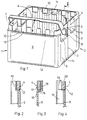
Bei der in Figur 1 dargestellten Ausführungsform der Erfindung ist ein Flaschenkasten längs seiner Längsmittelebene in zwei Hälften 1 und 2 unterteilt, die im Bereich einer Fuge 3 durch eine nicht gezeichnete Befestigungsvorrichtung miteinander verbunden sind. Jede dieser Hälften 1 und 2 weist einen Griffbügel 4 auf, der außen am oberen Rand 5 der beiden Seitenwände 6 einer Kastenhälfte um eine Achse 7 schwenkbar gelagert ist, die etwa in der Mitte der Seitenwand 6 angeordnet ist. Der Griffbügel 4 ist über die Achse 7 hinaus verlängert und weist an seinem Ende einen Vorsprung 8 auf, mit dem er beim Umlegen des Griffbügels 4 in die nicht gezeichnete Befestigungsvorrichtung eingreift und diese so verriegelt, daß die beiden Kastenhälften 1 und 2 starr miteinander verbunden sind. Die Kastenhälften weisen an der Innenfläche ihrer Längswand 9 lotrechtverlaufende Leisten 10 auf, die bei der dargestellten Ausführungsform als Hohlprofile ausgebildet sind. Sie ragen von der Wand 9 nach innen in den Zwischenraum zwischen zwei der in den Kasten eingesetzten Flaschen hinein. Die Flaschen liegen längs einer Linie 11 an der Innenfläche der Wände 9 an. Die Leisten 10 befinden sich daher im Bereich zwischen zwei benachbarten Berührungslinien 11. Der obere Rand 12 der Längswände 9 verläuft unterhalb des oberen Endes der Leisten 10, deren Höhe dem Sollmaß des Kastens entspricht. Diese Leisten ragen über den oberen Rand 12 der Längswand 9 so weit nach oben hinaus, als der Griffbügel 4 breit ist.In the embodiment of the invention shown in FIG. 1, a bottle crate is divided along its longitudinal center plane into two halves 1 and 2, which are connected to one another in the region of a
In Figur 1 ist der Griffbügel 4 der Kastenhälfte 2 in umgelegtem Zustand gezeichnet. Er liegt auf dem oberen Rand 12 der Längswand 9 der Kastenhälfte 2 auf, der in dieser Stellung obere Rand des Griffbügels 4 liegt etwa in einer Ebene mit den oberen Enden der Leisten 10. Im Bereich der Berührungslinie 11 ist zwischen zwei benachbarten Leisten 10 ein Zwischenraum 13, der bei umgelegtem Griffbügel 4 durch einen Bügelabschnitt nach außen abgedeckt ist, wobei dieser Abschnitt gegenüber der Innenfläche 18 der Kastenwand 9 etwas nach innen vorspringt. Die Außenfläche des Bügels kann in einer Ebene mit der Außenfläche einer Kastenwand liegen. Die äußere Begrenzung der oberen Leistenenden kann dann einen Abstand von der Ebene der Außenfläche der Kastenwand aufweisen, der der Dicke des Griffbügels entspricht.In Figure 1, the handle 4 of the box half 2 is drawn in the folded state. It lies on the
In Figur 1 ist der Griffbügel 4 der Kastenhälfte 1 in einer etwas hochgeschwenkten Stellung dargestellt, so daß die Zwischenräume 13 deutlich zu sehen sind.In Figure 1, the handle 4 of the box half 1 is shown in a slightly pivoted position so that the
Figur 2 zeigt einen Schnitt nach der Linie II - II in Figur 1 durch den oberen Bereich der Kastenhälfte 2. Der Griffbügel 4 liegt auf dem oberen Rand 12 einer Kastenlängswand 9 auf und verläuft hinter den Leisten 10. Dabei ist die Außenwand des umgelegten Bügels 4 bündig mit der Außenwand der Längswand 9. Der Bügel 4 ragt etwas über die Ebene der Innenfläche der Wand 9 hinaus nach innen. Sein Querschnitt ist dicker als die Wandstärke der Wand 9.FIG. 2 shows a section along the line II-II in FIG. 1 through the upper region of the box half 2. The handle 4 rests on the
Außer Öffnungen 14 in den Seitenwänden 6 des Kastens können auch die Längsseitenwände 9 in üblicher Weise Aussparungen aufweisen und im übrigen beliebig gestaltet sein. Nur der Einfachheit halber ist in Figur 1 ein teilbarer Kasten mit geschlossenen Längsseitenwänden dargestellt. Außerdem ist in Figur 1 die übliche Facheinteilung innerhalb des Kastens nicht dargestellt, auch nicht eine Längsleiste, die üblicherweise in der Teilungsebene die beiden Kastenhälften 1 und 2 abschließt und Teil eines Gefaches sein kann.In addition to
Figur 3 zeigt einen der Figur 2 entsprechenden Schnitt durch eine Ausführungsform eines Flaschenkastens, bei dem in der Höhe, in der bei der Ausführungsform nach Figur 1 sich der obere Rand 12 einer Längsseitenwand 9 befindet, eine Schulter 15 vorgesehen ist, auf der der umgelegte Bügel 4 aufliegt. An die Schulter 15 schließt sich eine bordartige hochstehende Randleiste 16 an, die bei der dargestellten Ausführungsform so hoch ist wie der Bügel 4 breit ist.FIG. 3 shows a section corresponding to FIG. 2 through an embodiment of a bottle crate, in which a
Bei dieser Ausführungsform der Erfindung sind an der Innenfläche der Wand 9 zumindest im Bereich ihres oberen Endes keine Leisten 10 vorgesehen. Die Innenfläche 17 des umgelegten Griffbügels 4 ragt über die Ebene der Innenfläche der Kastenwand etwas weiter nach innen und bildet so die Begrenzung des Kasteninnerns. Die Innenfläche des Griffbügels kann aber bei anderen Ausführungsformen in einer Ebene mit der Innenfläche 18 der Längsseitenwand des Kastens liegen. Nur in dem Abschnitt im Bereich der Berührungslinie 11, nämlich dort, wo in den Flaschenkasten eingestellte Flaschen eine Außenwand berühren, muß der Griffbügel so ausgebildet sein, daß das für die innere Kastenbegrenzung erforderliche Maß erreicht wird. In den anderen Abschnitten des Griffbügels 4 kann dessen Innenfläche 17 anders gestaltet sein, beispielsweise bei der Ausführungsform nach Figur 3 nach innen ragende Vorsprünge aufweisen, die in den Zwischenraum zwischen zwei benachbarten Flaschen eingreifen.In this embodiment of the invention, no
Bei der in Figur 4 dargestellten Ausführungsform ist der Schnitt durch ein Hohlprofil 10 des in Figur 1 dargestellten Flaschenkastens gelegt. Der Griffbügel 4 weist im Bereich eines Hohlprofils 10 einen Vorsprung 19 auf, der in eine Aussparung 20 auf der Rückseite des Hohlprofils 10 oder einer anderen Leiste eingreift. Die Leiste 10 und auch die Randleiste 16 können, wie in Figur 2 und 3 dargestellt, die Höhe des oberen Randes des umgelegten Griffbügels 4 erreichen. Sie können jedoch auch diesen oberen Rand des Griffbügels 4 überragen oder auch unterhalb von diesem Rand enden.In the embodiment shown in Figure 4, the section is made through a
Bei anderen Ausführungsformen der Erfindung können die den oberen Rand 12 der Längsseitenwand 9 überragenden Abschnitte der Leisten 10 auch fehlen, die Leisten 10 enden dann im Bereich des oberen Randes 12 der Längsseitenwand 9. Der umgelegte Griffbügel 4 liegt dann genauso wie bei den anderen Ausführungsformen auf dem oberen Rand 12 des Kastens auf, und sein oberer Rand bildet dann den oberen Abschluß der Längsseitenwände 9 des Kastens, so daß auch die Längsseitenwände 9 das Sollmaß für die Kastenhöhe aufweisen.In other embodiments of the invention, the sections of the
Auch kann bei Ausführungsformen der Erfindung der Griffbügel aus einem so steifen Werkstoff bestehen, daß seine Dicke der Dicke einer Kastenwand in etwa entspricht, zum Beispiel wenn der Bügel aus einem geeigneten, zum Beispiel verstärkten oder glasfaserverstärkten Kunststoff besteht. Dann kann bei Ausführungsformen der Erfindung sowohl die innere Fläche des Griffbügels, als auch seine äußere Fläche in einer Ebene mit der äußeren Fläche bzw. der Innenfläche der Kastenwand liegen. Dann ist es nicht notwendig, wegen des Griffbügels das Außenmaß oder das Innenmaß des Kastens gegenüber einem Kasten ohne Bügel zu ändern.In embodiments of the invention, the handle bracket can also consist of a material that is so rigid that its thickness corresponds approximately to the thickness of a box wall, for example if the bracket is made of a suitable, for example reinforced or glass fiber reinforced plastic. Then, in embodiments of the invention, both the inner surface of the handle and its outer surface can lie in one plane with the outer surface or the inner surface of the box wall. Then it is not necessary to change the outer dimension or the inner dimension of the box compared to a box without a bracket because of the handle.
Claims (10)
Applications Claiming Priority (2)
| Application Number | Priority Date | Filing Date | Title |
|---|---|---|---|
| DE4236484 | 1992-10-29 | ||
| DE4236484A DE4236484A1 (en) | 1992-10-29 | 1992-10-29 | Bottle crate |
Publications (3)
| Publication Number | Publication Date |
|---|---|
| EP0599028A2 true EP0599028A2 (en) | 1994-06-01 |
| EP0599028A3 EP0599028A3 (en) | 1995-01-25 |
| EP0599028B1 EP0599028B1 (en) | 1997-07-16 |
Family
ID=6471613
Family Applications (1)
| Application Number | Title | Priority Date | Filing Date |
|---|---|---|---|
| EP93115950A Expired - Lifetime EP0599028B1 (en) | 1992-10-29 | 1993-10-02 | Bottle crate |
Country Status (3)
| Country | Link |
|---|---|
| EP (1) | EP0599028B1 (en) |
| AT (1) | ATE155419T1 (en) |
| DE (2) | DE4236484A1 (en) |
Cited By (1)
| Publication number | Priority date | Publication date | Assignee | Title |
|---|---|---|---|---|
| US7156265B2 (en) * | 2001-12-05 | 2007-01-02 | Masterchem Industries Llc | Container |
Families Citing this family (4)
| Publication number | Priority date | Publication date | Assignee | Title |
|---|---|---|---|---|
| SE513904C2 (en) * | 1998-02-12 | 2000-11-27 | Lina Lindberg | Device at the basket to provide an ergonomically advantageous lifting and transport handle |
| EP1090845A1 (en) | 1999-10-06 | 2001-04-11 | Friedemann Rippel | Bottle crate |
| DE19948040C1 (en) * | 1999-10-06 | 2001-04-05 | Friedemann Rippel | Plastic crate for drinks bottles has lifting handles at base-level reducing the probability of breakage |
| EP1648787A2 (en) | 2003-07-09 | 2006-04-26 | Masterchem Industries, LLC. | Paint container handle |
Citations (2)
| Publication number | Priority date | Publication date | Assignee | Title |
|---|---|---|---|---|
| DE2933086A1 (en) * | 1979-08-16 | 1981-04-09 | Cremer, Peter, Dipl.-Kfm., 4600 Dortmund | Bottle pack case made of plastics material - is made in two sections in standard size and fitted with joints and locking elements formed as pins and holes |
| EP0388504A1 (en) * | 1989-03-22 | 1990-09-26 | Wilhelm Götz | Plastics crate in two parts |
Family Cites Families (2)
| Publication number | Priority date | Publication date | Assignee | Title |
|---|---|---|---|---|
| DE2933068A1 (en) * | 1979-08-16 | 1981-03-26 | Jürgen 7000 Stuttgart Demuth | Geothermal energy conversion to electric power - by coater circulating through deep boreholes into steam turbine |
| DE4024935A1 (en) * | 1990-08-06 | 1992-02-13 | Schoeller Plast Ag | STACKABLE BOTTLE BOX MADE OF PLASTIC |
-
1992
- 1992-10-29 DE DE4236484A patent/DE4236484A1/en not_active Ceased
-
1993
- 1993-10-02 AT AT93115950T patent/ATE155419T1/en not_active IP Right Cessation
- 1993-10-02 EP EP93115950A patent/EP0599028B1/en not_active Expired - Lifetime
- 1993-10-02 DE DE59306931T patent/DE59306931D1/en not_active Expired - Fee Related
Patent Citations (2)
| Publication number | Priority date | Publication date | Assignee | Title |
|---|---|---|---|---|
| DE2933086A1 (en) * | 1979-08-16 | 1981-04-09 | Cremer, Peter, Dipl.-Kfm., 4600 Dortmund | Bottle pack case made of plastics material - is made in two sections in standard size and fitted with joints and locking elements formed as pins and holes |
| EP0388504A1 (en) * | 1989-03-22 | 1990-09-26 | Wilhelm Götz | Plastics crate in two parts |
Cited By (1)
| Publication number | Priority date | Publication date | Assignee | Title |
|---|---|---|---|---|
| US7156265B2 (en) * | 2001-12-05 | 2007-01-02 | Masterchem Industries Llc | Container |
Also Published As
| Publication number | Publication date |
|---|---|
| DE59306931D1 (en) | 1997-08-21 |
| ATE155419T1 (en) | 1997-08-15 |
| EP0599028A3 (en) | 1995-01-25 |
| EP0599028B1 (en) | 1997-07-16 |
| DE4236484A1 (en) | 1994-05-05 |
Similar Documents
| Publication | Publication Date | Title |
|---|---|---|
| DE1586815C3 (en) | Bottle carrier | |
| DE2718067A1 (en) | STACKABLE BOTTLE CRATE MADE OF PLASTIC | |
| DE3709190C2 (en) | ||
| DE2408881C2 (en) | Carrier | |
| EP2673206B1 (en) | Box | |
| EP0599028B1 (en) | Bottle crate | |
| EP0208020A2 (en) | Bottle racks | |
| EP0293687B1 (en) | Plastic storage or transport container | |
| EP0231008B1 (en) | Stackable plastic crate | |
| DE4429945A1 (en) | Stackable transport container | |
| DE3927767A1 (en) | Plastic crate for carrying bottles - has openings in short sides with hinged flaps which fold upward and snap into U=section crosspiece used for handling | |
| DE4442836A1 (en) | Bottle crate | |
| EP0258549B2 (en) | Stackable bottle crate | |
| EP4253263A2 (en) | Bottle crate | |
| DE4304160A1 (en) | Shipping container | |
| DE7503830U (en) | Bottle crate and bottle carrier | |
| DE2915981C2 (en) | ||
| DE1253144B (en) | Container for stacking and nesting | |
| EP0485791B1 (en) | Plastic bottle crate | |
| CH496159A (en) | Plastic roller shutter slat | |
| DE8017829U1 (en) | Container for the transport of dangerous liquids | |
| EP0606073B1 (en) | Bottle crate | |
| DE102015007205A1 (en) | palette | |
| DE2709425C2 (en) | Folded product made from flexible material | |
| DE7911561U1 (en) | High-side bottle crate made of plastic |
Legal Events
| Date | Code | Title | Description |
|---|---|---|---|
| PUAI | Public reference made under article 153(3) epc to a published international application that has entered the european phase |
Free format text: ORIGINAL CODE: 0009012 |
|
| AK | Designated contracting states |
Kind code of ref document: A2 Designated state(s): AT BE CH DE DK ES FR GB GR IE IT LI LU MC NL PT SE |
|
| PUAL | Search report despatched |
Free format text: ORIGINAL CODE: 0009013 |
|
| AK | Designated contracting states |
Kind code of ref document: A3 Designated state(s): AT BE CH DE DK ES FR GB GR IE IT LI LU MC NL PT SE |
|
| RHK1 | Main classification (correction) |
Ipc: B65D 1/24 |
|
| 17P | Request for examination filed |
Effective date: 19950104 |
|
| 17Q | First examination report despatched |
Effective date: 19960425 |
|
| RAP1 | Party data changed (applicant data changed or rights of an application transferred) |
Owner name: BEROLINA KUNSTSTOFF-GESELLSCHAFT MBH & CO. VERPACK |
|
| GRAG | Despatch of communication of intention to grant |
Free format text: ORIGINAL CODE: EPIDOS AGRA |
|
| GRAH | Despatch of communication of intention to grant a patent |
Free format text: ORIGINAL CODE: EPIDOS IGRA |
|
| GRAH | Despatch of communication of intention to grant a patent |
Free format text: ORIGINAL CODE: EPIDOS IGRA |
|
| GRAA | (expected) grant |
Free format text: ORIGINAL CODE: 0009210 |
|
| AK | Designated contracting states |
Kind code of ref document: B1 Designated state(s): AT BE CH DE DK ES FR GB GR IE IT LI LU MC NL PT SE |
|
| PG25 | Lapsed in a contracting state [announced via postgrant information from national office to epo] |
Ref country code: IT Free format text: LAPSE BECAUSE OF FAILURE TO SUBMIT A TRANSLATION OF THE DESCRIPTION OR TO PAY THE FEE WITHIN THE PRESCRIBED TIME-LIMIT;WARNING: LAPSES OF ITALIAN PATENTS WITH EFFECTIVE DATE BEFORE 2007 MAY HAVE OCCURRED AT ANY TIME BEFORE 2007. THE CORRECT EFFECTIVE DATE MAY BE DIFFERENT FROM THE ONE RECORDED. Effective date: 19970716 Ref country code: GR Free format text: LAPSE BECAUSE OF FAILURE TO SUBMIT A TRANSLATION OF THE DESCRIPTION OR TO PAY THE FEE WITHIN THE PRESCRIBED TIME-LIMIT Effective date: 19970716 Ref country code: GB Effective date: 19970716 Ref country code: ES Free format text: THE PATENT HAS BEEN ANNULLED BY A DECISION OF A NATIONAL AUTHORITY Effective date: 19970716 Ref country code: DK Effective date: 19970716 |
|
| REF | Corresponds to: |
Ref document number: 155419 Country of ref document: AT Date of ref document: 19970815 Kind code of ref document: T |
|
| REG | Reference to a national code |
Ref country code: CH Ref legal event code: NV Representative=s name: NOVATOR AG Ref country code: CH Ref legal event code: EP |
|
| REF | Corresponds to: |
Ref document number: 59306931 Country of ref document: DE Date of ref document: 19970821 |
|
| PG25 | Lapsed in a contracting state [announced via postgrant information from national office to epo] |
Ref country code: SE Effective date: 19971016 |
|
| PG25 | Lapsed in a contracting state [announced via postgrant information from national office to epo] |
Ref country code: PT Effective date: 19971022 |
|
| ET | Fr: translation filed | ||
| PGFP | Annual fee paid to national office [announced via postgrant information from national office to epo] |
Ref country code: LU Payment date: 19971124 Year of fee payment: 5 |
|
| GBV | Gb: ep patent (uk) treated as always having been void in accordance with gb section 77(7)/1977 [no translation filed] |
Effective date: 19970716 |
|
| PG25 | Lapsed in a contracting state [announced via postgrant information from national office to epo] |
Ref country code: IE Free format text: LAPSE BECAUSE OF NON-PAYMENT OF DUE FEES Effective date: 19980330 |
|
| REG | Reference to a national code |
Ref country code: IE Ref legal event code: FD4D Ref document number: 75103 Country of ref document: IE |
|
| PG25 | Lapsed in a contracting state [announced via postgrant information from national office to epo] |
Ref country code: MC Free format text: LAPSE BECAUSE OF NON-PAYMENT OF DUE FEES Effective date: 19980430 |
|
| PLBE | No opposition filed within time limit |
Free format text: ORIGINAL CODE: 0009261 |
|
| STAA | Information on the status of an ep patent application or granted ep patent |
Free format text: STATUS: NO OPPOSITION FILED WITHIN TIME LIMIT |
|
| 26N | No opposition filed | ||
| PGFP | Annual fee paid to national office [announced via postgrant information from national office to epo] |
Ref country code: FR Payment date: 19980921 Year of fee payment: 6 |
|
| PG25 | Lapsed in a contracting state [announced via postgrant information from national office to epo] |
Ref country code: LU Free format text: LAPSE BECAUSE OF NON-PAYMENT OF DUE FEES Effective date: 19981002 |
|
| PGFP | Annual fee paid to national office [announced via postgrant information from national office to epo] |
Ref country code: BE Payment date: 19981016 Year of fee payment: 6 |
|
| PGFP | Annual fee paid to national office [announced via postgrant information from national office to epo] |
Ref country code: CH Payment date: 19981027 Year of fee payment: 6 |
|
| PGFP | Annual fee paid to national office [announced via postgrant information from national office to epo] |
Ref country code: DE Payment date: 19981028 Year of fee payment: 6 |
|
| PGFP | Annual fee paid to national office [announced via postgrant information from national office to epo] |
Ref country code: NL Payment date: 19981031 Year of fee payment: 6 Ref country code: AT Payment date: 19981031 Year of fee payment: 6 |
|
| PG25 | Lapsed in a contracting state [announced via postgrant information from national office to epo] |
Ref country code: AT Free format text: LAPSE BECAUSE OF NON-PAYMENT OF DUE FEES Effective date: 19991002 |
|
| PG25 | Lapsed in a contracting state [announced via postgrant information from national office to epo] |
Ref country code: LI Free format text: LAPSE BECAUSE OF NON-PAYMENT OF DUE FEES Effective date: 19991031 Ref country code: CH Free format text: LAPSE BECAUSE OF NON-PAYMENT OF DUE FEES Effective date: 19991031 Ref country code: BE Free format text: LAPSE BECAUSE OF NON-PAYMENT OF DUE FEES Effective date: 19991031 |
|
| BERE | Be: lapsed |
Owner name: BEROLINA KUNSTSTOFF-GESELLSCHAFT M.B.H. & CO. VER Effective date: 19991031 |
|
| PG25 | Lapsed in a contracting state [announced via postgrant information from national office to epo] |
Ref country code: NL Free format text: LAPSE BECAUSE OF NON-PAYMENT OF DUE FEES Effective date: 20000501 |
|
| REG | Reference to a national code |
Ref country code: CH Ref legal event code: PL |
|
| PG25 | Lapsed in a contracting state [announced via postgrant information from national office to epo] |
Ref country code: FR Free format text: LAPSE BECAUSE OF NON-PAYMENT OF DUE FEES Effective date: 20000630 |
|
| NLV4 | Nl: lapsed or anulled due to non-payment of the annual fee |
Effective date: 20000501 |
|
| PG25 | Lapsed in a contracting state [announced via postgrant information from national office to epo] |
Ref country code: DE Free format text: LAPSE BECAUSE OF NON-PAYMENT OF DUE FEES Effective date: 20000801 |
|
| REG | Reference to a national code |
Ref country code: FR Ref legal event code: ST |