EP0598680B1 - Skiboot - Google Patents
Skiboot Download PDFInfo
- Publication number
- EP0598680B1 EP0598680B1 EP93810774A EP93810774A EP0598680B1 EP 0598680 B1 EP0598680 B1 EP 0598680B1 EP 93810774 A EP93810774 A EP 93810774A EP 93810774 A EP93810774 A EP 93810774A EP 0598680 B1 EP0598680 B1 EP 0598680B1
- Authority
- EP
- European Patent Office
- Prior art keywords
- shaft
- cable
- tension lever
- rod
- ski boot
- Prior art date
- Legal status (The legal status is an assumption and is not a legal conclusion. Google has not performed a legal analysis and makes no representation as to the accuracy of the status listed.)
- Expired - Lifetime
Links
Images


Classifications
-
- A—HUMAN NECESSITIES
- A43—FOOTWEAR
- A43B—CHARACTERISTIC FEATURES OF FOOTWEAR; PARTS OF FOOTWEAR
- A43B5/00—Footwear for sporting purposes
- A43B5/04—Ski or like boots
- A43B5/0427—Ski or like boots characterised by type or construction details
- A43B5/047—Ski or like boots characterised by type or construction details provided with means to improve walking with the skiboot
- A43B5/0474—Ski or like boots characterised by type or construction details provided with means to improve walking with the skiboot having a walk/ski position
-
- A—HUMAN NECESSITIES
- A43—FOOTWEAR
- A43C—FASTENINGS OR ATTACHMENTS OF FOOTWEAR; LACES IN GENERAL
- A43C11/00—Other fastenings specially adapted for shoes
- A43C11/16—Fastenings secured by wire, bolts, or the like
Definitions
- the present invention relates to a shell ski boot comprising a shell bottom intended to wrap the foot and the heel, a rod in two parts articulated on the shell bottom and a device for closing and tightening the rod around the leg comprising a tensioning lever articulated on the back of the rod about a horizontal axis, this tensioning lever being folded down, in the direction of the heel, in the closed position and exerting traction on a tightening cable, and means for locking the rod in the lowering position.
- Such a shoe is known from document FR-A-2 657 235.
- the means for locking the rod on the bottom of the shell in the descent position consist of a support member articulated on the rear part of the rod and driven towards its support position on the bottom of the shell by the end of the tensioning lever against the bias of a spring tending to move the support member from its support position.
- Shoes are also known in which the locking of the upper on the shell bottom in the lowering position is ensured by an auxiliary rocker (EP-A-0 086 908 and FR-A-2 648 327).
- the present invention also aims to provide the function of locking the upper in the down position without an auxiliary device in a shoe of the type defined above, but by making it possible to easily obtain a stable and comfortable position for rest and walking. and return as easily to the locked position.
- the shoe according to the invention is characterized in that the means for locking the upper in the descent position, are constituted by the tensioning lever itself and that the tensioning lever is provided with a movable stop cooperating with the back of the rod in such a way that in a position of this stop, the tensioning lever is slightly moved away from the rod and cannot lock the rod in the descent position.
- the tensioning lever abuts against the bottom of the shell to lock the rod in the lowering position, but in a particular embodiment the tensioning lever comes to lock on a rear part of the front part of the rod.
- the tensioning lever has a projection directed towards the shell in the folded position, projection cooperating with a stop formed on the bottom of the shell.
- the rod locking means according to the invention are equally applicable to a shoe with conventional rear entry, that is to say with a rear cover articulated near the malleolus, as to a shoe of the type described in the patent.
- FR-A-2 657 235 in which the rear cover is articulated at the very rear of the shoe or to a shoe as described in patent FR-A-2 673 081, that is to say a shoe the two parts of the stem of which close edge to edge so as to form a collar.
- Figure 1 shows a shoe according to a first embodiment in the boot position.
- Figure 2 shows the same shoe in the closed descent position.
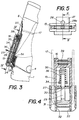
- Figure 3 is a longitudinal sectional view, along III-III of Figure 5, of the tensioning lever of the first embodiment, in the boot position.
- Figure 4 is a sectional view along IV-IV of Figure 3 of the tensioning lever according to the first embodiment.
- Figure 5 is a bottom-up view of the tensioning lever of the first embodiment.
- FIG. 6 partially shows a second embodiment in the descent position.
- Figure 7 shows the second embodiment in the on position.
- Figure 8 is a partial view of this second embodiment in the boot position.
- Figure 9 shows a third embodiment.
- Figure 10 shows a fourth embodiment.
- the shoe represented in FIGS. 1 and 2 is of the same type as the shoe described in patent application FR-A-2 673 081. It comprises a shell bottom 1 with variable volume surrounding the foot and the heel and closing on the foot by two flaps 2. On the shell bottom 1 is articulated, at the height of the malleoli, a rod 3 whose articulation is materialized by rivets 4.
- the rod 3 consists of a front part 5 and a rear part 6 both articulated at 4 and closing like the two parts of a box on the two sides of the shoe, along two lines of joint 7 so as to form a collar (FIG. 2), the front part 5 having for this purpose flaps 8, 9 and 10.
- the part 5 forms a bridge 5a at the rear above the heel.
- rear padding 11 secured to the rear part 6 of the upper and the protruding part 12 of the inner comfort liner.
- the parts 11 and 12 can be independent to form together a removable liner.
- a strap 13 which surrounds the leg at the level of part 12 of the boot.
- the bottom of the shell 1 is equipped with a double cable tightening loop 14.
- the rod is fitted, on its rear part 6, with a tensioning lever 15 articulated around a horizontal axis 16 and traversed by a cable 17, one end of which is fixed to a rectangular plate 18 slidably mounted in a rectangular housing 19 provided on the outer side of the front part 5 of the rod and covered with a plate 20 which has been given the form of a double loop similar to the loop 14 for aesthetic reasons.
- the housing 19 has, on the one hand, a guiding function and, on the other hand, a stop function limiting the stroke towards the rear of the plate 18.
- the other end of the cable 17 is anchored on the inner side of the shoe, on the front part 5 of the upper.
- the sliding plate 18 is connected to the flap 9 by a cable 21 and to the flap 10 by a cable 22.
- the cable 17 is further guided by guide profiles 23 formed inside the rear part 6 of the rod. This guide 23 could be replaced by any other means of returning the cable.
- the tensioner lever 15 has at its end a spout 24. On each side of this spout 24, the tensioner lever has, on the shoe side, a rounded profile which is applied to the flare of the shoe in the folded position of the lever- tensioner and, on the outside, a form offering grip to the skier. For its part, the bottom of the shell has a stop 26 at the height of the heel.
- the tensioning lever 15 is further equipped with a movable transverse plate 27 whose role will be explained below.
- the folding of the tensioning lever 15 downwards simultaneously has the effect of closing the two parts 5 and 6 of the rod and of tightening the collar thus formed by pulling on the flaps 9 and 10 by means of the sliding plate 18.
- the cable 17 has passed under the articulation axis 16 of the tensioning lever, as shown in FIG. 2, it tends to apply the tensioning lever against the shoe.
- the beak 24 of the tensioning lever comes to be placed above the stop 26, thus locking the rod in the descent position.
- This plate 27 has a cutout 28 in the form of a keyhole ( Figure 5), that is to say having a part upper circular extended downward by a narrower portion 28a with parallel edges.
- the wafer 27 is crossed by a cylindrical bar 29 of diameter slightly smaller than the diameter of the circular part 28 of the wafer in order to be able to slide easily in this circular part.
- the bar 29 also has in its middle part a narrowing 30 of diameter slightly less than the width of the narrow part 28a of the hole in the plate 27, so that the plate 27 can be moved transversely on the bar 29 in the part narrowed 30 to lock this bar.
- the lower end of the bar 29 has a slide-shaped head 31 which can slide in a guide formed by two ribs 32 and 33 of the tensioning lever 15.
- This head 31 is crossed by the cable 17 which also crosses the two ribs 32 and 33 by two longitudinal lights.
- the part of the bar 29 located on the other side of the plate 27 relative to the head 31 is provided with a washer 34, which could be a nut, against which abuts a spring 35 working in compression in a housing 36 provided in the tensioning lever 15.
- the tension on the cable 17 is released, within the limits of the total compression of the spring 35, which has the effect of relieving the tension on the flaps 9 and 10 and allowing a slight opening from the collar to the joint 7, as shown in FIG. 7.
- the rod can therefore oscillate, thus allowing easy walking.
- the spring 35 maintains a certain elastic tension on the cable 17 during walking, so that the upper of the shoe will remain closed, but in a flexible and comfortable manner.
- FIGS. 3 and 4 it can also be seen how the tensioning lever 15 is articulated on the rear part 6 of the upper of the shoe.
- the tensioning lever 15 is mounted in a groove 37 formed in the profiled back of part 6 of the rod and its fork-shaped end is articulated on a projection 38.
- FIGS 6 and 7 show a second embodiment of the tensioner lever 15 comprising means ensuring the same functions as the plate 27 and the bar 29 of the previous embodiment.
- the plate is replaced by a pusher 39 surrounded by a spring 40 working in compression between the head of this pusher and the back of the tensioning lever 15.
- This pusher 17 is provided with a hook 41 behind which the loop is hooked formed by cable 17.
- the locking can therefore take place between the two parts 5 and 6 of the upper of the shoe, by one of the means described above.
- FIG. 9 illustrates an exemplary embodiment using the means represented in FIGS. 6 to 8 to define a ski position and a walking position.
- the spout 24 of the tensioning lever 15 engages, in the locking position, in a hole 43 in the bridge-shaped part 5a of the front part 5 of the rod which replaces the stop 26.
- the locking of the tensioning lever 15 on the front part 5 of the rod has the effect, in combination with the attachment of the cable 17 behind the hook 41, to lock the collar in the closed position.
- FIG. 10 represents a shoe with a rear boot, the upper of which consists of a front part 44 articulated on the bottom of the shell by means of two rivets 4 at the malleolus and of a rear part 45 articulated completely the rear of the shoe on two extensions of the part 44 around an axis 46 located just above the stop 26 of the bottom of the shell 1.
- the tensioning lever 15 is articulated around an axis 16 on the part posterior 45 of the rod and comes, by its beak 24, to lock on the stop 26 of the bottom of the shell. There are also shown here two enlargements 47 of the tensioning lever 15 allowing its operation.
- the movable plate 27 comes to rest against the part 45 of the rod. For the rest, this shoe is similar to the shoe according to the first embodiment.
Abstract
Description
La présente invention a pour objet une chaussure de ski à coque comprenant un bas de coque destiné à envelopper le pied et le talon, une tige en deux parties articulée sur le bas de coque et un dispositif de fermeture et de serrage de la tige autour de la jambe comprenant un levier-tendeur articulé sur le dos de la tige autour d'un axe horizontal, ce levier-tendeur étant rabattu vers le bas, en direction du talon, en position de fermeture et exerçant une traction sur un câble de serrage, et des moyens de verrouillage de la tige en position de descente.The present invention relates to a shell ski boot comprising a shell bottom intended to wrap the foot and the heel, a rod in two parts articulated on the shell bottom and a device for closing and tightening the rod around the leg comprising a tensioning lever articulated on the back of the rod about a horizontal axis, this tensioning lever being folded down, in the direction of the heel, in the closed position and exerting traction on a tightening cable, and means for locking the rod in the lowering position.
Une telle chaussure est connue du document FR-A-2 657 235. Dans cette chaussure, les moyens de verrouillage de la tige sur le bas de coque en position de descente sont constitués d'un organe d'appui articulé sur la partie postérieure de la tige et entraîné vers sa position d'appui sur le bas de coque par l'extrémité du levier-tendeur contre la sollicitation d'un ressort ayant tendance à écarter l'organe d'appui de sa position d'appui.Such a shoe is known from document FR-A-2 657 235. In this shoe, the means for locking the rod on the bottom of the shell in the descent position consist of a support member articulated on the rear part of the rod and driven towards its support position on the bottom of the shell by the end of the tensioning lever against the bias of a spring tending to move the support member from its support position.
On connaît par ailleurs des chaussures dans lesquelles le verrouillage de la tige sur le bas de coque en position de descente est assuré par une bascule auxiliaire (EP-A-0 086 908 et FR-A-2 648 327).Shoes are also known in which the locking of the upper on the shell bottom in the lowering position is ensured by an auxiliary rocker (EP-A-0 086 908 and FR-A-2 648 327).
Il a par ailleurs déjà été proposé, dans le brevet FR-A-2 428 413, de verrouiller la tige au moyen d'un bossage formé à l'extrémité inférieure d'un crochet relié à des moyens de serrage du pied. Ce bossage sert simultanément à l'accrochage du crochet qui pivote, par son bossage, sur le bord du bas de coque lors de la fermeture et de l'ouverture de la chaussure. Le verrouillage de la tige se fait certes sans dispositif auxiliaire, mais la tige ne peut être déverrouillée sans décrocher le crochet et il peut en outre être difficile de remettre le crochet en place.It has moreover already been proposed, in patent FR-A-2 428 413, to lock the rod by means of a boss formed at the lower end of a hook connected to means for clamping the foot. This boss is used simultaneously for hooking the hook which pivots, by its boss, on the edge of the bottom of the shell when closing and the opening of the shoe. The rod is locked without an auxiliary device, but the rod cannot be unlocked without unhooking the hook and it can also be difficult to put the hook back in place.
La présente invention a également pour but d'assurer la fonction de verrouillage de la tige en position de descente sans dispositif auxiliaire dans une chaussure de type défini plus haut, mais en permettant d'obtenir facilement une position stable et confortable de repos et de marche et de revenir aussi facilement en position verrouillée.The present invention also aims to provide the function of locking the upper in the down position without an auxiliary device in a shoe of the type defined above, but by making it possible to easily obtain a stable and comfortable position for rest and walking. and return as easily to the locked position.
La chaussure selon l'invention est caractérisée en ce que les moyens de verrouillage de la tige en position de descente, sont constitués par le levier-tendeur lui-même et que le levier-tendeur est muni d'une butée mobile coopérant avec le dos de la tige de telle manière que dans une position de cette butée, le levier-tendeur est légèrement écarté de la tige et ne peut pas verrouiller la tige en position de descente.The shoe according to the invention is characterized in that the means for locking the upper in the descent position, are constituted by the tensioning lever itself and that the tensioning lever is provided with a movable stop cooperating with the back of the rod in such a way that in a position of this stop, the tensioning lever is slightly moved away from the rod and cannot lock the rod in the descent position.
En général le levier-tendeur vient buter contre le bas de coque pour verrouiller la tige en position de descente, mais dans une forme d'exécution particulière le levier-tendeur vient se verrouiller sur une partie arrière de la partie antérieure de la tige.In general, the tensioning lever abuts against the bottom of the shell to lock the rod in the lowering position, but in a particular embodiment the tensioning lever comes to lock on a rear part of the front part of the rod.
Selon une forme d'exécution de l'invention, le levier-tendeur présente une saillie dirigée vers la coque en position rabattue, saillie coopérant avec une butée formée sur le bas de coque.According to one embodiment of the invention, the tensioning lever has a projection directed towards the shell in the folded position, projection cooperating with a stop formed on the bottom of the shell.
Les moyens de verrouillage de la tige selon l'invention sont aussi bien applicables à une chaussure à entrée arrière conventionnelle, c'est-à-dire à capot arrière articulé près de la malléole, qu'à une chaussure du type décrit dans le brevet FR-A-2 657 235, dans laquelle le capot arrière est articulé tout à l'arrière de la chaussure ou à une chaussure telle que décrite dans le brevet FR-A-2 673 081, c'est-à-dire une chaussure dont les deux parties de la tige se ferment bord à bord de manière à former une collier.The rod locking means according to the invention are equally applicable to a shoe with conventional rear entry, that is to say with a rear cover articulated near the malleolus, as to a shoe of the type described in the patent. FR-A-2 657 235, in which the rear cover is articulated at the very rear of the shoe or to a shoe as described in patent FR-A-2 673 081, that is to say a shoe the two parts of the stem of which close edge to edge so as to form a collar.
Le dessin annexé représente, à titre d'exemple, quatre formes d'exécution de l'invention.The accompanying drawing shows, by way of example, four embodiments of the invention.
La figure 1 représente une chaussure selon une première forme d'exécution en position de chaussage.Figure 1 shows a shoe according to a first embodiment in the boot position.
La figure 2 représente la même chaussure en position fermée de descente.Figure 2 shows the same shoe in the closed descent position.
La figure 3 est une vue en coupe longitudinale, selon III-III de la figure 5, du levier-tendeur de la première forme d'exécution, en position de chaussage.Figure 3 is a longitudinal sectional view, along III-III of Figure 5, of the tensioning lever of the first embodiment, in the boot position.
La figure 4 est une vue en coupe selon IV-IV de la figure 3 du levier-tendeur selon la première forme d'exécution.Figure 4 is a sectional view along IV-IV of Figure 3 of the tensioning lever according to the first embodiment.
La figure 5 est une vue de bas en haut du levier-tendeur de la première forme d'exécution.Figure 5 is a bottom-up view of the tensioning lever of the first embodiment.
La figure 6 représente, partiellement, une deuxième forme d'exécution en position de descente.FIG. 6 partially shows a second embodiment in the descent position.
La figure 7 représente la deuxième forme d'exécution en position de marche.Figure 7 shows the second embodiment in the on position.
La figure 8 est une vue partielle de cette deuxième forme d'exécution en position de chaussage.Figure 8 is a partial view of this second embodiment in the boot position.
La figure 9 représente une troisième forme d'exécution.Figure 9 shows a third embodiment.
La figure 10 représente une quatrième forme d'exécution.Figure 10 shows a fourth embodiment.
La chaussure représentée aux figures 1 et 2 est du même type que la chaussure décrite dans la demande de brevet FR-A-2 673 081. Elle comprend un bas de coque 1 à volume variable entourant le pied et le talon et se fermant sur le pied par deux rabats 2. Sur le bas de coque 1 est articulée, à la hauteur des malléoles, une tige 3 dont l'articulation est matérialisée par des rivets 4. La tige 3 est constituée d'une partie antérieure 5 et d'une partie postérieure 6 toutes deux articulées en 4 et venant se fermer comme les deux parties d'une boîte sur les deux côtés de la chaussure, selon deux lignes de joint 7 de manière à former un collier (figure 2), la partie antérieure 5 présentant à cet effet des rabats 8, 9 et 10. Comme représenté dans la demande de brevet FR-A-2 673 081, la partie 5 forme un pont 5a à l'arrière au-dessus du talon.The shoe represented in FIGS. 1 and 2 is of the same type as the shoe described in patent application FR-A-2 673 081. It comprises a
On distingue en outre le rembourrage arrière usuel 11 solidaire de la partie postérieure 6 de la tige et la partie dépassante 12 du chausson intérieur de confort. De manière connue, les parties 11 et 12 peuvent être indépendantes pour former ensemble un chausson amovible. Dans la partie supérieure de la partie 6 est en outre fixée une courroie 13 venant entourer la jambe au niveau de la partie 12 du chausson.There is also the usual
Le bas de coque 1 est équipé d'une double boucle de serrage à câbles 14.The bottom of the
La tige est équipée, sur sa partie postérieure 6, d'un levier-tendeur 15 articulé autour d'un axe horizontal 16 et traversé par un câble 17 dont une extrémité est fixée à une plaquette rectangulaire 18 montée coulissante dans un logement rectangulaire 19 prévu sur le côté extérieur de la partie antérieure 5 de la tige et recouvert d'une plaque 20 à laquelle on a donné la forme d'une double boucle analogue à la boucle 14 pour des raisons esthétiques. Le logement 19 a, d'une part, une fonction de guidage et, d'autre part, une fonction de butée limitant la course vers l'arrière de la plaquette 18. L'autre extrémité du câble 17 est ancrée sur le côté intérieur de la chaussure, sur la partie antérieure 5 de la tige. La plaquette coulissante 18 est reliée au rabat 9 par un câble 21 et au rabat 10 par un câble 22. Le câble 17 est en outre guidé par des profils de guidage 23 formés à l'intérieur de la partie postérieure 6 de la tige. Ce guidage 23 pourrait être remplacé par tout autre moyen de renvoi du câble.The rod is fitted, on its
Le levier-tendeur 15 présente à son extrémité un bec 24. De chaque côté de ce bec 24, le levier-tendeur présente, côté chaussure, un profil arrondi venant s'appliquer sur l'arrondi de la chaussure en position rabattue du levier-tendeur et, côté extérieur, une forme offrant prise au skieur. De son côté, le bas de coque présente une butée 26 à la hauteur du talon. Le levier-tendeur 15 est en outre équipé d'une plaquette transversale mobile 27 dont le rôle sera exposé plus loin.The
Dans la position de chaussage représentée à la figure 1, le levier-tendeur 15 est relevé et le câble 17 est relâché au maximum, de telle sorte que les deux parties 5 et 6 de la tige peuvent être écartées l'une de l'autre et que les rabats 9 et 10 sont également relâchés, la plaquette coulissante 18 étant en butée vers l'avant dans son logement 19. Cette position peut permettre également la marche, mais de façon non idéale.In the boot position shown in Figure 1, the
Le rabattement du levier-tendeur 15 vers le bas a simultanément pour effet de fermer les deux parties 5 et 6 de la tige et de serrer le collier ainsi formé en tirant sur les rabats 9 et 10 par l'intermédiaire de la plaquette coulissante 18. Une fois que le câble 17 a passé sous l'axe d'articulation 16 du levier-tendeur, comme représenté à la figure 2, il a tendance à appliquer le levier-tendeur contre la chaussure. Lors de la fermeture du levier-tendeur ou à l'occasion de la première flexion de la jambe, le bec 24 du levier-tendeur vient se placer au-dessus de la butée 26, verrouillant ainsi la tige en position de descente.The folding of the
Dans la position représentée à la figure 2, en écartant légèrement le levier-tendeur 15 de la chaussure de manière à dégager le bec 24 de la butée 26, il est possible de redresser la tige de la chaussure, dans les limites formées par la partie de la coque s'étendant sur le cou-de-pied, contre laquelle la partie antérieure 5 vient buter. Toutefois, lors de la première flexion de la jambe le levier-tendeur 15 vient aussitôt se verrouiller à nouveau sur la butée 26. Une marche n'est donc pas possible sans un aménagement particulier du levier-tendeur permettant de maintenir à volonté la butée 26 hors de la trajectoire du bec 24 du levier-tendeur. Cet aménagement est représenté en détail aux figures 3 à 5. Il est constitué essentiellement de la plaquette mobile 27 montée transversalement au levier-tendeur 15. Cette plaquette 27 présente une découpe 28 en forme de trou de serrure (figure 5), c'est-à-dire présentant une partie supérieure circulaire prolongée vers le bas par une partie plus étroite 28a à bords parallèles. La plaquette 27 est traversée par une barre cylindrique 29 de diamètre légèrement inférieur au diamètre de la partie circulaire 28 de la plaquette afin de pouvoir coulisser facilement dans cette partie circulaire. La barre 29 présente en outre dans sa partie médiane un rétrécissement 30 de diamètre légèrement inférieur à la largeur de la partie étroite 28a du trou de la plaquette 27, de telle manière que la plaquette 27 peut être déplacée transversalement sur la barre 29 dans la partie rétrécie 30 pour verrouiller cette barre. L'extrémité inférieure de la barre 29 présente une tête 31 en forme de coulisseau pouvant coulisser dans un guidage formé par deux nervures 32 et 33 du levier-tendeur 15. Cette tête 31 est traversée par le câble 17 qui traverse en outre les deux nervures 32 et 33 par deux lumières longitudinales. La partie de la barre 29 située de l'autre côté de la plaquette 27 relativement à la tête 31 est munie d'une rondelle 34, qui pourrait être un écrou, contre laquelle vient buter un ressort 35 travaillant en compression dans un logement 36 ménagé dans le levier-tendeur 15.In the position shown in Figure 2, by slightly moving the
Dans la position représentée aux figures 3 et 4, la plaquette 27 ne dépasse pratiquement pas le levier-tendeur en direction de la chaussure et la barre 29 est verrouillée longitudinalement par la plaquette 27. Le bec 24 du levier-tendeur peut venir en butée contre la butée 26. On est donc en position de ski ou de descente.In the position shown in FIGS. 3 and 4, the
Si l'on désire libérer la tige de manière à ce qu'elle puisse osciller autour de son articulation 4, il suffit d'écarter légèrement le levier-tendeur 15 de la chaussure et de repousser la plaquette 27 en direction de la chaussure. La tige 29 peut alors coulisser dans la partie circulaire du trou 28 de la plaquette sous l'effet de la tension de serrage exercée sur le câble 17 qui repousse la tête 31 en comprimant le ressort 35 dont la force est sensiblement inférieure à la force de serrage de la chaussure. La plaquette 27 se trouve ainsi verrouillée à son tour en position repoussée et comme elle vient buter contre la chaussure, elle maintient le levier-tendeur 15 légèrement écarté de la chaussure, c'est-à-dire le bec 24 hors de la portée de la butée 26. D'autre part, la tension sur le câble 17 est relâchée, dans les limites de la compression totale du ressort 35, ce qui a pour effet de relâcher la tension sur les rabats 9 et 10 et de permettre une légère ouverture du collier au joint 7, comme représenté à la figure 7. La tige peut dès lors osciller, permettant ainsi une marche aisée. Le ressort 35 maintient une certaine tension élastique sur la câble 17 lors de la marche, de sorte que la tige de la chaussure restera fermée, mais d'une manière souple et confortable.If it is desired to release the upper so that it can oscillate around its
Pour ramener la barre 29 dans la position représentée au dessin, il suffit d'ouvrir complètement le levier-tendeur 15, dans la position représentée à la figure 1, de manière à relâcher complètement la tension sur le câble 17. Le ressort 35 peut alors repousser la barre 29 et lorsque la partie rétrécie 30 de cette barre arrive en face de la plaquette 27, il est possible de repousser la plaquette dans la position représentée au dessin. La barre 29 est à nouveau verrouillée par la plaquette 27 et il suffit de refermer le levier-tendeur pour se retrouver en position de descente.To return the
Sur les figures 3 et 4 on voit en outre comment le levier-tendeur 15 est articulé sur la partie postérieure 6 de la tige de la chaussure. Le levier-tendeur 15 est monté dans une gorge 37 formé dans le dos profilé de la partie 6 de la tige et son extrémité en forme de fourche est articulée sur une saillie 38.In FIGS. 3 and 4, it can also be seen how the tensioning
Les figures 6 et 7 représentent une seconde forme d'exécution du levier-tendeur 15 comportant des moyens assurant les mêmes fonctions que la plaquette 27 et la barre 29 de la forme d'exécution précédente. La plaquette est remplacée par un poussoir 39 entouré d'un ressort 40 travaillant en compression entre la tête de ce poussoir et le dos du levier-tendeur 15. Ce poussoir 17 est muni d'un crochet 41 derrière lequel vient s'accrocher la boucle formée par le câble 17.Figures 6 and 7 show a second embodiment of the
Pour passer dans la position de marche représentée à la figure 7, il suffit de soulever un peu le levier-tendeur 15 tout en pressant sur le bouton-poussoir 39 et de verrouiller celui-ci en position pressée. Ce verrouillage peut être assuré par un poussoir transversal venant derrière le crochet 41 ou par un dispositif à baïonnette permettant de verrouiller le poussoir par une légère rotation. La boucle de câble 17 libérée vient comprimer un ressort 42 analogue au ressort 35 de la forme d'exécution précédente.To pass into the on position shown in FIG. 7, it suffices to lift the tensioning lever 15 a little while pressing on the
Pour ramener le câble en arrière dans sa position d'accrochage, il suffit de relever complètement le levier-tendeur 15 comme représenté à la figure 8. Le câble 17 étant complètement relâché, le ressort 42 repousse le câble contre le bouton-poussoir 39 qui est alors libéré de sorte que son crochet 41 vient à nouveau retenir le câble 17.To return the cable back to its hooking position, it suffices to completely raise the
On a vu que dans une chaussure du type considéré jusqu'ici, les deux parties 5, 6 de la tige, une fois fermées le long de leur ligne de joint 7, forment un collier. En position serrée, ce collier vient s'appuyer dans la zone du cou-de-pied sur les rabats du bas de coque 1 qui s'oppose au pivotement du collier vers l'arrière, c'est-à-dire au redressement de la jambe.We have seen that in a shoe of the type considered so far, the two
Si l'on accepte une certaine flexibilité de la chaussure, le verrouillage peut dès lors avoir lieu entre les deux parties 5 et 6 de la tige de la chaussure, par l'un des moyens décrits précédemment.If a certain flexibility of the shoe is accepted, the locking can therefore take place between the two
La figure 9 illustre un exemple d'exécution utilisant les moyens représentés aux figure 6 à 8 pour définir une position de ski et une position de marche. Le bec 24 du levier-tendeur 15 vient s'engager, en position de verrouillage, dans un trou 43 de la partie en forme de pont 5a de la partie antérieure 5 de la tige qui remplace la butée 26. Dans ce cas, le verrouillage du levier-tendeur 15 sur la partie antérieure 5 de la tige a pour effet, en combinaison avec l'accrochage du câble 17 derrière le crochet 41, de verrouiller le collier en position fermée.FIG. 9 illustrates an exemplary embodiment using the means represented in FIGS. 6 to 8 to define a ski position and a walking position. The
Lorsque le bouton-poussoir 39 est amené dans la position représentée à la figure 7, le câble 17 est relâché et vient comprimer le ressort 42 et le bec 24 du levier-tendeur 15 est écarté du trou 43. La relaxation du câble a pour effet de desserrer le collier et de permettre un écartement de ces deux parties au niveau de la ligne de joint 7. Comme à la figure 7, la plaque coulissante 18 vient occuper une position intermédiaire et la tige de la chaussure peut osciller autour de son articulation 4, autorisant ainsi la marche. Lors de la marche, la plaque coulissante 18 peut effectuer un mouvement de va-et-vient comme indiqué par la double flèche sur la figure 7.When the
La figure 10 représente une chaussure à chaussage par l'arrière dont la tige est constituée d'une partie antérieure 44 articulée sur le bas de coque au moyen de deux rivets 4 au niveau de la malléole et d'une partie postérieure 45 articulée tout à l'arrière de la chaussure sur deux prolongements de la partie 44 autour d'un axe 46 situé juste au-dessus de la butée 26 du bas de coque 1. Le levier-tendeur 15 est articulé autour d'un axe 16 sur la partie postérieure 45 de la tige et vient, par son bec 24, se verrouiller sur la butée 26 du bas de coque. On a en outre représenté ici deux élargissements 47 du levier-tendeur 15 permettant sa manoeuvre. La plaquette mobile 27 vient s'appuyer contre la partie 45 de la tige. Pour le reste, cette chaussure est analogue à la chaussure selon la première forme d'exécution.FIG. 10 represents a shoe with a rear boot, the upper of which consists of a
Claims (7)
- A ski boot with a shell having a lower part (1) for enclosing the foot and the heel, a shaft (3) in two parts (5, 6) articulated on the lower part of the shell, and means for closing and tightening said shaft on a leg, said closing and tightening means comprising a tension lever (15) articulated on the back of said shaft (3) around an horizontal axis (16), said tension lever being turned down, in the direction of the heel, in the closed position and pulling a tightening cable (17) and locking means for blocking said shaft in a downhill position, characterised in that said locking means for blocking the shaft in the downhill position are constituted by said tension lever (15, 24), in that said tension lever (15) has a movable abutment (27, 39) co-operating with the back of said shaft in such a way that in one position of said abutment, the tension lever is slightly spaced from said shaft and can not block said shaft in the downhill position.
- A ski boot as claimed in claim 1, characterised in that said tension lever (15) has a tooth (24) extending in the direction of the shaft in folded down position, said tooth co-operating with an abutment (26) formed on the lower part of the shell for locking the shaft on the lower part of the shell (1).
- A Ski boot as claimed in claim 1, wherein said shaft has an anterior part (5) and a posterior part (6) both articulated on a common axis and being applied edge to edge one against the other in the closed position in order to form a collar which can be tightened by the anterior part, said anterior part having flaps (8, 9, 10), and said parts being connected at the back by a bridge (5a) extending over the heel, characterised in that said tension lever (15) has a tooth fitting in a hole (43) of the bridge (5a) of the anterior part of the shaft when said tension lever is in folded down position, so that both parts of the shaft are blocked in the closed position.
- A ski boot as claimed in any of claims 1 to 3, characterised in that said movable abutment (27, 39) has holding means (28a, 41) for holding said tightening cable (17) and releasing said cable when said abutment is placed in the position in which said tension lever is spaced from said shaft.
- A ski boot as claimed in claim 4, characterised in that said tension lever (15) has a longitudinal housing (36), said housing containing a compression spring (35; 42) and having lateral openings through which said cable passes, said cable being pushed by said spring in the direction of the extremity of the tension lever so that said cable (17) is automatically brought back in a hooking position on said movable abutment by said spring when said cable is released by a total opening of said tension lever.
- A ski boot as claimed in claim 5, characterised in that said movable abutment (39) is provided with a hook (41) for retaining said cable.
- A ski boot as claimed in claim 5, characterised in that said movable abutment is constituted by a plate (27) having an keyhole-shaped opening (28) through which passes a rod (29) fixed to a head (31) enclosing the cable, said rod having a narrow part (30) allowing said rod to be blocked by said plate, when said plate is in retracted position.
Applications Claiming Priority (2)
| Application Number | Priority Date | Filing Date | Title |
|---|---|---|---|
| CH3534/92 | 1992-11-18 | ||
| CH03534/92A CH688072A5 (en) | 1992-11-18 | 1992-11-18 | ski boot. |
Publications (2)
| Publication Number | Publication Date |
|---|---|
| EP0598680A1 EP0598680A1 (en) | 1994-05-25 |
| EP0598680B1 true EP0598680B1 (en) | 1996-08-28 |
Family
ID=4258070
Family Applications (1)
| Application Number | Title | Priority Date | Filing Date |
|---|---|---|---|
| EP93810774A Expired - Lifetime EP0598680B1 (en) | 1992-11-18 | 1993-11-09 | Skiboot |
Country Status (4)
| Country | Link |
|---|---|
| EP (1) | EP0598680B1 (en) |
| AT (1) | ATE141760T1 (en) |
| CH (1) | CH688072A5 (en) |
| DE (1) | DE69304290D1 (en) |
Families Citing this family (5)
| Publication number | Priority date | Publication date | Assignee | Title |
|---|---|---|---|---|
| US6378230B1 (en) * | 2000-11-06 | 2002-04-30 | Visual3D Ltd. | Lace-less shoe |
| EP2612568A1 (en) | 2012-01-04 | 2013-07-10 | K-2 Corporation | Ski/walk mechanism |
| ITUB20156282A1 (en) * | 2015-12-04 | 2017-06-04 | Scarpa Calzaturificio Spa | SKI BOOT |
| ITUB20156243A1 (en) * | 2015-12-04 | 2017-06-04 | Scarpa Calzaturificio Spa | SKI BOOT |
| FR3050619A1 (en) * | 2016-04-28 | 2017-11-03 | Pierre Gignoux | TENSIONER FOR CLAMPING SHOE |
Family Cites Families (3)
| Publication number | Priority date | Publication date | Assignee | Title |
|---|---|---|---|---|
| CH644501A5 (en) * | 1982-02-18 | 1984-08-15 | Lange Int Sa | SKI BOOT. |
| FR2647649A1 (en) * | 1989-06-01 | 1990-12-07 | Lange Int Sa | Ski boot |
| CH678685A5 (en) * | 1989-06-15 | 1991-10-31 | Lange Int Sa | Ski boot with leg locked forward by rocker |
-
1992
- 1992-11-18 CH CH03534/92A patent/CH688072A5/en not_active IP Right Cessation
-
1993
- 1993-11-09 EP EP93810774A patent/EP0598680B1/en not_active Expired - Lifetime
- 1993-11-09 AT AT93810774T patent/ATE141760T1/en not_active IP Right Cessation
- 1993-11-09 DE DE69304290T patent/DE69304290D1/en not_active Expired - Lifetime
Also Published As
| Publication number | Publication date |
|---|---|
| ATE141760T1 (en) | 1996-09-15 |
| DE69304290D1 (en) | 1996-10-02 |
| EP0598680A1 (en) | 1994-05-25 |
| CH688072A5 (en) | 1997-05-15 |
Similar Documents
| Publication | Publication Date | Title |
|---|---|---|
| EP0097382B1 (en) | Closing device for a sports shoe | |
| EP0286586B1 (en) | Ski boot | |
| EP0144100B1 (en) | Rear access ski boot | |
| FR2661076A1 (en) | Ski boot having an articulated upper with a locked descent position and a released rest or walking position. | |
| FR2656989A1 (en) | "BACK ENTRY" TYPE ALPINE SKI BOOT. | |
| EP0375604B1 (en) | Ski boot | |
| FR2564711A1 (en) | Closure device for a rear-entry ski boot | |
| FR2739572A1 (en) | LONGITUDINALLY ADJUSTABLE SKI FIXING BASE | |
| EP0407336B1 (en) | Rear-entry ski boot | |
| EP1106218B1 (en) | Cross-country ski | |
| EP0598680B1 (en) | Skiboot | |
| FR2654904A1 (en) | SKI SHOE IN PLASTIC MATERIAL. | |
| EP0689777B1 (en) | Ski boot | |
| CH686162A5 (en) | ski boot. | |
| FR2619999A1 (en) | ALPINE SKI SHOE WITH ARTICULATED SHAFT ON HULL | |
| EP0740909B1 (en) | Skiboot | |
| EP0705545A1 (en) | Closing- and clamping device for a ski boot | |
| EP0588757B1 (en) | Ski boot | |
| EP0671134B1 (en) | Skiboot made of plastics | |
| EP0712586A1 (en) | Skiboot | |
| EP0598681B1 (en) | Skiboot | |
| FR2654903A1 (en) | Plastic ski boot | |
| EP0761114B1 (en) | Ski boot | |
| FR2587177A1 (en) | SHOE FOR SKI | |
| CH686275A5 (en) | ski boot. |
Legal Events
| Date | Code | Title | Description |
|---|---|---|---|
| PUAI | Public reference made under article 153(3) epc to a published international application that has entered the european phase |
Free format text: ORIGINAL CODE: 0009012 |
|
| 17P | Request for examination filed |
Effective date: 19940209 |
|
| AK | Designated contracting states |
Kind code of ref document: A1 Designated state(s): AT DE FR IT |
|
| 17Q | First examination report despatched |
Effective date: 19951120 |
|
| GRAH | Despatch of communication of intention to grant a patent |
Free format text: ORIGINAL CODE: EPIDOS IGRA |
|
| GRAH | Despatch of communication of intention to grant a patent |
Free format text: ORIGINAL CODE: EPIDOS IGRA |
|
| GRAA | (expected) grant |
Free format text: ORIGINAL CODE: 0009210 |
|
| AK | Designated contracting states |
Kind code of ref document: B1 Designated state(s): AT DE FR IT |
|
| PG25 | Lapsed in a contracting state [announced via postgrant information from national office to epo] |
Ref country code: AT Effective date: 19960828 |
|
| REF | Corresponds to: |
Ref document number: 141760 Country of ref document: AT Date of ref document: 19960915 Kind code of ref document: T |
|
| REF | Corresponds to: |
Ref document number: 69304290 Country of ref document: DE Date of ref document: 19961002 |
|
| ITF | It: translation for a ep patent filed |
Owner name: BUGNION S.P.A. |
|
| PG25 | Lapsed in a contracting state [announced via postgrant information from national office to epo] |
Ref country code: DE Effective date: 19961129 |
|
| PLBE | No opposition filed within time limit |
Free format text: ORIGINAL CODE: 0009261 |
|
| STAA | Information on the status of an ep patent application or granted ep patent |
Free format text: STATUS: NO OPPOSITION FILED WITHIN TIME LIMIT |
|
| 26N | No opposition filed | ||
| PGFP | Annual fee paid to national office [announced via postgrant information from national office to epo] |
Ref country code: FR Payment date: 19981022 Year of fee payment: 6 |
|
| PG25 | Lapsed in a contracting state [announced via postgrant information from national office to epo] |
Ref country code: FR Free format text: LAPSE BECAUSE OF NON-PAYMENT OF DUE FEES Effective date: 20000731 |
|
| REG | Reference to a national code |
Ref country code: FR Ref legal event code: ST |
|
| PG25 | Lapsed in a contracting state [announced via postgrant information from national office to epo] |
Ref country code: IT Free format text: LAPSE BECAUSE OF NON-PAYMENT OF DUE FEES;WARNING: LAPSES OF ITALIAN PATENTS WITH EFFECTIVE DATE BEFORE 2007 MAY HAVE OCCURRED AT ANY TIME BEFORE 2007. THE CORRECT EFFECTIVE DATE MAY BE DIFFERENT FROM THE ONE RECORDED. Effective date: 20051109 |