EP0097382B1 - Closing device for a sports shoe - Google Patents
Closing device for a sports shoe Download PDFInfo
- Publication number
- EP0097382B1 EP0097382B1 EP83200334A EP83200334A EP0097382B1 EP 0097382 B1 EP0097382 B1 EP 0097382B1 EP 83200334 A EP83200334 A EP 83200334A EP 83200334 A EP83200334 A EP 83200334A EP 0097382 B1 EP0097382 B1 EP 0097382B1
- Authority
- EP
- European Patent Office
- Prior art keywords
- latch
- arm
- hook
- shoe
- support
- Prior art date
- Legal status (The legal status is an assumption and is not a legal conclusion. Google has not performed a legal analysis and makes no representation as to the accuracy of the status listed.)
- Expired
Links
Images
Classifications
-
- A—HUMAN NECESSITIES
- A43—FOOTWEAR
- A43C—FASTENINGS OR ATTACHMENTS OF FOOTWEAR; LACES IN GENERAL
- A43C11/00—Other fastenings specially adapted for shoes
- A43C11/14—Clamp fastenings, e.g. strap fastenings; Clamp-buckle fastenings; Fastenings with toggle levers
- A43C11/1406—Fastenings with toggle levers; Equipment therefor
- A43C11/142—Fastenings with toggle levers with adjustment means provided for on the shoe, e.g. rack
- A43C11/1433—Fastenings with toggle levers with adjustment means provided for on the shoe, e.g. rack characterised by means to decrease required force for the closure movement of the toggle lever
-
- A—HUMAN NECESSITIES
- A43—FOOTWEAR
- A43C—FASTENINGS OR ATTACHMENTS OF FOOTWEAR; LACES IN GENERAL
- A43C11/00—Other fastenings specially adapted for shoes
- A43C11/14—Clamp fastenings, e.g. strap fastenings; Clamp-buckle fastenings; Fastenings with toggle levers
- A43C11/1406—Fastenings with toggle levers; Equipment therefor
-
- Y—GENERAL TAGGING OF NEW TECHNOLOGICAL DEVELOPMENTS; GENERAL TAGGING OF CROSS-SECTIONAL TECHNOLOGIES SPANNING OVER SEVERAL SECTIONS OF THE IPC; TECHNICAL SUBJECTS COVERED BY FORMER USPC CROSS-REFERENCE ART COLLECTIONS [XRACs] AND DIGESTS
- Y10—TECHNICAL SUBJECTS COVERED BY FORMER USPC
- Y10T—TECHNICAL SUBJECTS COVERED BY FORMER US CLASSIFICATION
- Y10T24/00—Buckles, buttons, clasps, etc.
- Y10T24/21—Strap tighteners
- Y10T24/2102—Cam lever and loop
- Y10T24/2104—Step adjusted
- Y10T24/2106—Ski boot and garment fasteners
-
- Y—GENERAL TAGGING OF NEW TECHNOLOGICAL DEVELOPMENTS; GENERAL TAGGING OF CROSS-SECTIONAL TECHNOLOGIES SPANNING OVER SEVERAL SECTIONS OF THE IPC; TECHNICAL SUBJECTS COVERED BY FORMER USPC CROSS-REFERENCE ART COLLECTIONS [XRACs] AND DIGESTS
- Y10—TECHNICAL SUBJECTS COVERED BY FORMER USPC
- Y10T—TECHNICAL SUBJECTS COVERED BY FORMER US CLASSIFICATION
- Y10T24/00—Buckles, buttons, clasps, etc.
- Y10T24/21—Strap tighteners
- Y10T24/2102—Cam lever and loop
- Y10T24/2142—Ski boot and garment fasteners
-
- Y—GENERAL TAGGING OF NEW TECHNOLOGICAL DEVELOPMENTS; GENERAL TAGGING OF CROSS-SECTIONAL TECHNOLOGIES SPANNING OVER SEVERAL SECTIONS OF THE IPC; TECHNICAL SUBJECTS COVERED BY FORMER USPC CROSS-REFERENCE ART COLLECTIONS [XRACs] AND DIGESTS
- Y10—TECHNICAL SUBJECTS COVERED BY FORMER USPC
- Y10T—TECHNICAL SUBJECTS COVERED BY FORMER US CLASSIFICATION
- Y10T24/00—Buckles, buttons, clasps, etc.
- Y10T24/21—Strap tighteners
- Y10T24/2183—Ski, boot, and shoe fasteners
Landscapes
- Footwear And Its Accessory, Manufacturing Method And Apparatuses (AREA)
- Braking Arrangements (AREA)
Abstract
Description
La présente invention a pour objet un dispositif de fermeture de deux parties d'une chaussure de sport, particulièrement destiné à fermer une chaussure de ski présentant deux parties latérales dont les bords sont recouverts par une partie ou languette médiane, ce dispositif comportant essentiellement un organe de liaison, par exemple une boucle, articulé sur un levier tendeur autour d'un axe autour duquel est monté un ressort ayant tendance à maintenir le levier tendeur et l'organe de liaison contre la chaussure.The present invention relates to a device for closing two parts of a sports boot, particularly intended for closing a ski boot having two lateral parts, the edges of which are covered by a middle part or tongue, this device essentially comprising a member. link, for example a loop, articulated on a tension lever around an axis around which is mounted a spring tending to hold the tension lever and the connecting member against the shoe.
Un dispositif de ce type est décrit dans le brevet US-4051 611. Ce dispositif comprend un levier tendeur articulé sur un support fixé à l'une des parties de la chaussure et sur lequel est articulé un organe de liaison comportant une boucle destinée à s'accrocher dans une crémaillère fixée sur l'autre partie de la chaussure (voir aussi FR-A-1 366 146). Dans le cas d'une chaussure comportant deux parties latérales dont les bords sont recouverts par une partie médiane en forme de languette, la crémaillère et le levier tendeur doivent être fixés sur les deux parties latérales de la chaussure en deux points relativement très écartés l'un de l'autre de manière à pouvoir fermer la chaussure en rapprochant l'une de l'autre les deux parties latérales, sans que ce rapprochement soit gêné par la partie médiane de la chaussure. Ceci nécessite l'emploi d'un long élément de liaison, c'est-à-dire longue boucle. En position ouverte de la chaussure, cette longue boucle est embarrassante car elle risque de s'accrocher à l'autre chaussure ou à tout objet situé à proximité de la chaussure et de s'abîmer.A device of this type is described in patent US-4051 611. This device comprises a tensioning lever articulated on a support fixed to one of the parts of the shoe and on which is articulated a connecting member comprising a loop intended for s 'hang in a rack fixed on the other part of the shoe (see also FR-A-1 366 146). In the case of a shoe comprising two lateral parts, the edges of which are covered by a middle part in the form of a tongue, the rack and the tensioning lever must be fixed on the two lateral parts of the shoe at two relatively distant points. one of the other so as to be able to close the shoe by bringing the two lateral parts closer to one another, without this approximation being hindered by the middle part of the shoe. This requires the use of a long connecting element, that is to say a long loop. In the open position of the shoe, this long loop is embarrassing because it risks catching on the other shoe or any object located near the shoe and being damaged.
La présente invention a précisément pour but de permettre d'écarter les points de fixation du support du levier tendeur et du point de solidari- sation de l'élément de liaison à l'autre partie de la chaussure sans allonger l'élément de liaison. A cet effet, dans le dispositif de fermeture selon l'invention, le levier tendeur est articulé à l'extrémité d'au moins un bras dont l'autre extrémité est articulée autour d'un axe sur un support destiné à être fixé à l'une des parties de la chaussure, en arrière de l'axe d'articulation du levier. En position fermée, l'axe d'articulation du levier sur le bras est donc situé au-dessus de la partie médiane de la chaussure. D'autre part, un ressort monté autour de l'axe d'articulation de l'organe de liaison sur le levier tendeur a tendance à maintenir l'organe de liaison contre la chaussure, de telle sorte qu'en position ouverte du dispositif le levier tendeur et l'organe de liaison ont tendance à être maintenus en appui contre la chaussure, en diminuant ainsi l'encombrement du dispositif en position ouverte. Le dispositif comporte en outre des moyens de verrouillage du levier tendeur à l'axe d'articulation du bras au support fixé à la chaussure et le levier est muni d'un dispositif de commande pour le déverrouiller.The object of the present invention is precisely to allow the attachment points of the support of the tensioning lever and of the point of attachment of the connecting element to the other part of the shoe to be moved away without elongating the connecting element. To this end, in the closure device according to the invention, the tensioning lever is articulated at the end of at least one arm, the other end of which is articulated around an axis on a support intended to be fixed to the 'one of the parts of the shoe, behind the axis of articulation of the lever. In the closed position, the axis of articulation of the lever on the arm is therefore located above the middle part of the shoe. On the other hand, a spring mounted around the hinge axis of the connecting member on the tensioning lever tends to hold the connecting member against the shoe, so that in the open position of the device the tensioning lever and the connecting member tend to be held in abutment against the shoe, thereby reducing the size of the device in the open position. The device further comprises means for locking the tensioning lever to the articulation axis of the arm to the support fixed to the shoe and the lever is provided with a control device for unlocking it.
Selon un mode d'exécution le dispositif comporte un crochet mobile monté dans le levier tendeur et soumis à l'action d'un ressort qui tend à le maintenir accroché à l'axe d'articulation du bras sur son support pour verrouiller le levier tendeur en position fermée, rabattue, le crochet étant muni d'un bras coopérant avec un bras auxiliaire à l'extrémité libre du levier tendeur et prolongeant cette extrémité, pour dégager ledit chrochet de l'axe d'articulation du bras lorsque le levier tendeur est soulevé par son extrémité constituée du levier auxiliaire. Le levier tendeur est ainsi verrouillé en position fermée par son crochet.According to one embodiment, the device comprises a movable hook mounted in the tensioning lever and subjected to the action of a spring which tends to keep it attached to the articulation axis of the arm on its support to lock the tensioning lever in the closed, folded position, the hook being provided with an arm cooperating with an auxiliary arm at the free end of the tensioning lever and extending this end, to release said hook from the articulation axis of the arm when the tensioning lever is lifted by its end consisting of the auxiliary lever. The tensioning lever is thus locked in the closed position by its hook.
Il a certes déjà été proposé, dans le modèle d'utilité DE-8 002 933, de munir un levier tendeur d'un crochet destiné à s'accrocher dans un cran du support du levier tendeur. Le cran étant situé à l'extrémité de la plaque recourbée constituant le support du levier tendeur, un tel dispositif ne peut être monté que sur une partie de chaussure de courbure déterminée. Ce n'est pas le cas du dispositif selon l'invention car le support du bras portant le levier tendeur peut avoir différentes inclinaisons sans influence sur la position de l'axe d'articulation auquel vient s'accrocher le crochet du levier tendeur.It has certainly already been proposed, in the utility model DE-8 002 933, to provide a tensioning lever with a hook intended to hang in a notch of the support of the tensioning lever. The notch being located at the end of the curved plate constituting the support of the tensioning lever, such a device can only be mounted on a part of a shoe of determined curvature. This is not the case for the device according to the invention because the support of the arm carrying the tensioning lever can have different inclinations without influence on the position of the articulation axis to which the hook of the tensioning lever is hooked.
Selon une exécution préféré de l'invention, l'organe de liaison est constitué par une boucle articulée sur le levier tendeur par l'intermédiaire d'un dispositif de réglage de longueur, cette boucle venant s'accrocher dans les dents d'une crémaillère fixée sur l'autre partie de la chaussure. Il est toutefois possible d'inverser ces éléments en utilisant une boucle articulée sur la partie de la chaussure opposée au levier tendeur, un crochet simple ou en forme de crémaillère étant articulé sur le levier tendeur pour l'accrochage de la boucle.According to a preferred embodiment of the invention, the connecting member is constituted by a loop articulated on the tensioning lever by means of a length adjusting device, this loop coming to hang in the teeth of a rack attached to the other part of the shoe. It is however possible to reverse these elements by using a hinged loop on the part of the shoe opposite the tensioning lever, a simple hook or in the form of a rack being articulated on the tensioning lever for hooking the loop.
Le dessin annexé représente, à titre d'exemple, une forme d'exécution de l'invention.
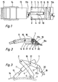
- La figure 1 représente une vue de dessus du dispositif.
- La figure 2 représente une vue partielle en coupe selon II-II de la figure 1.
- La figure 3 représente le dispositif en position ouverte.
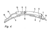
- La figure 4 est une vue de profil du dispositif complet monté sur une chaussure de ski en trois parties.
- Figure 1 shows a top view of the device.
- FIG. 2 represents a partial sectional view along II-II of FIG. 1.
- Figure 3 shows the device in the open position.
- Figure 4 is a side view of the complete device mounted on a three-part ski boot.
Le dispositif représenté au dessin comprend un levier tendeur 1 articulé en des points 2 et 3 à deux bras parallèles 4 et 5 et entre ces deux bras, les autres extrémités des bras 4 et 5 étant articulées autour d'un axe 6 sur les deux joues d'un étrier 7 fixé sur une partie latérale 8 d'une chaussure de ski comportant une autre partie latérale 9 et une troisième partie 10 recouvrant les bords opposés des parties latérales 8 et 9. Le levier tendeur 1 est en forme de fourche entre les doigts de laquelle est articulée une tige 11 autour d'un axe 12. La tige 11 présente une partie filetée 11 a sur laquelle est vissé un bloc 13 sur lequel est articulée une boucle 14 destinée à s'accrocher à un crochet multiple 15 en forme de crémaillère fixé par un rivet à la partie latérale 9 de la chaussure. Un ressort en cor de chasse 16 monté autour de l'axe 12, a tendance à maintenir le levier 1 et la tige 11 appliqués contre la chaussure.The device shown in the drawing comprises a
Dans un évidement du levier tendeur 1 de largeur sensiblement égale à la distance séparant les deux bras du levier tendeur, est monté un crochet 17 articulé autour d'un axe 18 et muni d'un bras 17a s'étendant en direction de l'extrémité du levier tendeur 1 et venant s'appuyer à l'extrémité d'un levier auxiliaire 19 articulé autour d'un axe 20 à l'extrémité du levier tendeur 1 et présentant un prolongement 19a pour son actionnement par le doigt de l'utilisateur. Un ressort en cor de chasse 21 est monté autour de l'axe 18, ses extrémités s'appuyant respectivement sur le levier tendeur et sur le crochet 17, de manière à maintenir celui-ci appuyé contre l'extrémité du levier 19.In a recess of the
Dans la position fermée représentée aux figures 2 et 4, le crochet 17 est accroché à l'axe d'articulation 6 des bras 4 et 5. Pour ouvrir le dispositif, l'utilisateur soulève le levier tendeur par le bras 19a du levier auxiliaire, ce qui a pour effet de faire pivoter le crochet 17 et de le dégager de l'axe 6. L'utilisateur peut alors ouvrir le dispositif comme représenté à la figure 3. Dans cette position ouverte, la tige de l'organe de liaison est rabattue sur la chaussure grâce au ressort 16. Lorsque l'utilisateur relâche le levier tendeur, l'extrémité du levier tendeur vient également s'appuyer sur la chaussure grâce au même ressort 16. Dans cette position, le dispositif, bien qu'en position ouverte, présente un encombrement réduit. Dans tous les cas, les bras 4 et 5 ne basculent pas vers l'extérieur de la chaussure (vers la droite si l'on considère la figure 3) et la tige 11, avec sa boucle 14, est également empêchée d'être projetée loin de la chaussure, mais reste au contraire appuyée contre la chaussure sans risquer de s'accrocher accidentellement et d'être endommagée.In the closed position shown in FIGS. 2 and 4, the
Pour fermer le dispositif, on accroche la boucle 14 au crochet 15 et l'on rabat le levier tendeur 1. Lors de ce rabattement, la rampe 17b du crochet 17 glisse sur l'axe 6 et le crochet 17 vient s'accrocher sous cet axe 6.To close the device, the
Il ressort de la figure 4 que l'axe d'articulation 2 du levier tendeur 1 sur son support est situé au-dessus de la partie médiane 10 de la chaussure et que l'élément de liaison constitué par la tige 11 et la boucle 14 est maintenu relativement court, alors que cet élément de liaison serait beaucoup plus long si le levier tendeur était articulé autour de l'axe 6 comme c'est le cas des boucles de l'art antérieur. En outre, le verrouillage du levier tendeur est indépendant de l'inclinaison du support 7 relativement au levier tendeur. Le dispositif peut être dégagé complètement de la languette médiane 10 de la chaussure.It appears from FIG. 4 that the
Le dispositif peut faire l'objet de nombreuses variantes sans sortir du cadre de l'invention. Par exemple, le crochet 17 pourrait être coulissant au lieu d'être pivotant. Dans ce cas, il peut être dégagé par un poussoir ou par tout autre moyen, par exemple deux pièces mobiles montées de chaque côté du levier tendeur et reliées à une barrette solidaire du crochet. Le levier tendeur et les bras d'articulation pourraient être réalisés différement. Par exemple, les bras pourraient être articulés à l'intérieur du levier tendeur et non à l'extérieur.The device can be the subject of numerous variants without departing from the scope of the invention. For example, the
Selon une autre forme d'exécution, le crochet 17 pourrait être pivoté sur le support 7, par exemple autour de l'axe 6, et venir s'accrocher dans le levier tendeur 1. Le dégagement d'un tel crochet pourrait se faire de la même manière que représenté à la figure 2. Dans cette variante d'exécution, comme dans l'exécution représentée, l'axe 6 est utilisé simultanément pour l'articulation des bras et pour le verrouillage.According to another embodiment, the
Claims (6)
Priority Applications (1)
| Application Number | Priority Date | Filing Date | Title |
|---|---|---|---|
| AT83200334T ATE16446T1 (en) | 1982-06-22 | 1983-03-10 | CLOSING DEVICE FOR SPORTS SHOES. |
Applications Claiming Priority (2)
| Application Number | Priority Date | Filing Date | Title |
|---|---|---|---|
| US06/390,838 US4424636A (en) | 1982-06-22 | 1982-06-22 | Buckle fastener, notably for sports footwear |
| US390838 | 1982-06-22 |
Publications (2)
| Publication Number | Publication Date |
|---|---|
| EP0097382A1 EP0097382A1 (en) | 1984-01-04 |
| EP0097382B1 true EP0097382B1 (en) | 1985-11-13 |
Family
ID=23544152
Family Applications (1)
| Application Number | Title | Priority Date | Filing Date |
|---|---|---|---|
| EP83200334A Expired EP0097382B1 (en) | 1982-06-22 | 1983-03-10 | Closing device for a sports shoe |
Country Status (6)
| Country | Link |
|---|---|
| US (1) | US4424636A (en) |
| EP (1) | EP0097382B1 (en) |
| JP (1) | JPS596003A (en) |
| AT (1) | ATE16446T1 (en) |
| CA (1) | CA1209792A (en) |
| DE (1) | DE3361196D1 (en) |
Families Citing this family (36)
| Publication number | Priority date | Publication date | Assignee | Title |
|---|---|---|---|---|
| DE8329344U1 (en) * | 1982-10-12 | 1983-11-24 | Icaro Olivieri & C. S.p.A., Montebelluna, Treviso | Fastener for ski boots with adjustable tensioner to change the buckle tension without first releasing the fastener |
| IT8422395V0 (en) * | 1984-06-25 | 1984-06-25 | Olivieri Icaro & C | TENSIONING GROUP FOR THE LACING OF A SPORT FOOTWEAR, PARTICULARLY OF A SKI BOOT. |
| CH685970A5 (en) * | 1992-01-29 | 1995-11-30 | Lange Int Sa | A tensioning device for a ski boot. |
| CH689195A5 (en) * | 1993-06-11 | 1998-12-15 | Lange Int Sa | Device for closing a ski boot. |
| IT1279339B1 (en) * | 1995-07-31 | 1997-12-09 | Nordica Spa | CLAMPING DEVICE FOR SPORT SHOES |
| WO1997028859A1 (en) * | 1996-02-06 | 1997-08-14 | Preston Binding Company | Snowboard binding assembly |
| US5745959A (en) * | 1997-01-07 | 1998-05-05 | The Burton Corporation | Ratchet-type buckle |
| IT1298824B1 (en) * | 1998-03-27 | 2000-02-02 | Htm Sport Spa | LEVER STRUCTURE, ESPECIALLY FOR SPORTS FOOTWEAR |
| US6431423B1 (en) | 1999-11-23 | 2002-08-13 | Yakima Products, Inc. | Assembly for carrying a bicycle on a vehicle |
| US6561398B1 (en) | 1999-11-23 | 2003-05-13 | Yakima Products, Inc. | Rack assembly for a vehicle |
| US6425509B1 (en) | 1999-11-23 | 2002-07-30 | Yakima Products, Inc. | Bicycle carrier |
| US6422441B1 (en) | 1999-11-23 | 2002-07-23 | Yakima Products, Inc. | Apparatus for securing recreational equipment to vehicle-mounted racks |
| US20020089151A1 (en) | 2001-01-09 | 2002-07-11 | Carrasca Robert G. | Hinge strap for snowboard conventional binding |
| US7726528B2 (en) * | 2005-08-09 | 2010-06-01 | Yakima Products, Inc. | Bicycle carrier |
| US7726529B2 (en) * | 2006-08-09 | 2010-06-01 | Yakima Products, Inc. | Bicycle carrier |
| US8660656B2 (en) * | 2009-10-16 | 2014-02-25 | Hanger, Inc. | Cuff assembly |
| US8387282B2 (en) | 2010-04-26 | 2013-03-05 | Nike, Inc. | Cable tightening system for an article of footwear |
| US11684111B2 (en) | 2012-02-22 | 2023-06-27 | Nike, Inc. | Motorized shoe with gesture control |
| US11071344B2 (en) | 2012-02-22 | 2021-07-27 | Nike, Inc. | Motorized shoe with gesture control |
| EP2630887A1 (en) * | 2012-02-23 | 2013-08-28 | CK Montres & Bijoux Co., S.A. | Wristwatch provided with a clasp |
| US9376063B2 (en) | 2012-04-30 | 2016-06-28 | Yakima Products, Inc. | Vehicle carrier system |
| US9283884B2 (en) | 2012-04-30 | 2016-03-15 | Yakima Produtcs, Inc. | Attachment devices for vehicle rooftop rack accessories |
| EP3871548B1 (en) | 2012-08-31 | 2024-04-03 | NIKE Innovate C.V. | Motorized tensioning system |
| EP4331428A3 (en) | 2012-08-31 | 2024-05-01 | Nike Innovate C.V. | Motorized tensioning system with sensors |
| EP2981185B1 (en) * | 2013-04-04 | 2017-05-31 | Roland Iten Mechanical Luxury SA | Buckle for a belt or strap such as a watch strap |
| AT513839B1 (en) * | 2013-08-30 | 2014-08-15 | Atomic Austria Gmbh | Skischuhschnalle to close the shell of a ski boot and equipped with ski boot |
| US10035695B2 (en) | 2014-03-11 | 2018-07-31 | Jimmy R. Rider | Buckle assembly for a stirrup strap |
| US9629418B2 (en) | 2014-04-15 | 2017-04-25 | Nike, Inc. | Footwear having motorized adjustment system and elastic upper |
| US9326566B2 (en) | 2014-04-15 | 2016-05-03 | Nike, Inc. | Footwear having coverable motorized adjustment system |
| US10092065B2 (en) | 2014-04-15 | 2018-10-09 | Nike, Inc. | Footwear having motorized adjustment system and removable midsole |
| USD784632S1 (en) | 2015-03-11 | 2017-04-18 | Jimmy R. Rider | Buckle for a stirrup strap |
| AU2016250078B2 (en) * | 2015-04-17 | 2019-11-28 | Vision Quest Industries Incorporated Dba Vq Orthocare | Orthotic device with snap fit cuff and latch mechanism |
| EP3313331A4 (en) * | 2015-06-23 | 2019-04-24 | The Regents of the University of California | A mechanism for efficient donning and doffing of an exoskeleton |
| CN109661327B (en) | 2016-06-05 | 2022-06-03 | 雅捷马产品公司 | Fork-mounted bicycle carrier |
| AU2017278256B2 (en) | 2016-06-05 | 2022-09-01 | Yakima Products, Inc. | Upright bike carrier |
| US10857949B2 (en) | 2017-04-18 | 2020-12-08 | Yakima Products, Inc. | Fork mount bicycle carrier |
Family Cites Families (3)
| Publication number | Priority date | Publication date | Assignee | Title |
|---|---|---|---|---|
| FR1366146A (en) * | 1963-05-29 | 1964-07-10 | Actis Ets | Hook for shoe closure |
| CH429505A (en) * | 1965-01-07 | 1967-01-31 | Bally Schuhfab Ag | Tension lever lock on ski boots |
| DE1685813A1 (en) * | 1966-03-23 | 1971-09-02 | Franz March | Buckle, especially for a ski boot |
-
1982
- 1982-06-22 US US06/390,838 patent/US4424636A/en not_active Expired - Fee Related
-
1983
- 1983-03-10 AT AT83200334T patent/ATE16446T1/en not_active IP Right Cessation
- 1983-03-10 DE DE8383200334T patent/DE3361196D1/en not_active Expired
- 1983-03-10 EP EP83200334A patent/EP0097382B1/en not_active Expired
- 1983-04-12 CA CA000425691A patent/CA1209792A/en not_active Expired
- 1983-05-02 JP JP58076359A patent/JPS596003A/en active Granted
Also Published As
| Publication number | Publication date |
|---|---|
| JPS6224081B2 (en) | 1987-05-27 |
| US4424636A (en) | 1984-01-10 |
| CA1209792A (en) | 1986-08-19 |
| ATE16446T1 (en) | 1985-11-15 |
| DE3361196D1 (en) | 1985-12-19 |
| JPS596003A (en) | 1984-01-13 |
| EP0097382A1 (en) | 1984-01-04 |
Similar Documents
| Publication | Publication Date | Title |
|---|---|---|
| EP0097382B1 (en) | Closing device for a sports shoe | |
| EP0248149B1 (en) | Ski boot | |
| EP0086908B1 (en) | Ski-shoe | |
| CA1331388C (en) | Hinge type ski bindings for cross-country skiing | |
| CH616832A5 (en) | ||
| EP0242531A1 (en) | Closure means for shoes and ski boot provided therewith | |
| EP0300955B1 (en) | Tensioning device for a holding cable in a ski-boot | |
| EP0093458B1 (en) | Closing device for a sports shoe | |
| FR2807671A1 (en) | ATTACHMENT FOR RETAINING A SHOE ON A SLIDING OR ROLLING MACHINE | |
| EP0287508A2 (en) | Ski boot with an automatic closure device | |
| EP0768102A1 (en) | Length adjustable skibinding groundplate | |
| EP0242526A1 (en) | Ski-boot | |
| EP1106218B1 (en) | Cross-country ski | |
| WO1995025447A1 (en) | Strap clasp | |
| CH690894A5 (en) | Folding clasp, in particular with button. | |
| FR2742997A1 (en) | Clamp to hold boot on snow-board or ski | |
| EP0588757B1 (en) | Ski boot | |
| EP0598680B1 (en) | Skiboot | |
| CH685971A5 (en) | A closure device of a ski boot upper. | |
| FR2860729A1 (en) | RETAINING ELEMENT OF A SHOE ON A SLIDING OR ROLLING BOARD | |
| EP2415364B1 (en) | Lever with extension for fastening a sports shoe | |
| FR2708430A1 (en) | Closure device for a ski boot | |
| EP0414642A2 (en) | Ski boot | |
| FR2755374A1 (en) | Fastener for ski-shoe on ski | |
| FR2663552A1 (en) | Device for locking and unlocking means for adjusting a ski boot |
Legal Events
| Date | Code | Title | Description |
|---|---|---|---|
| PUAI | Public reference made under article 153(3) epc to a published international application that has entered the european phase |
Free format text: ORIGINAL CODE: 0009012 |
|
| AK | Designated contracting states |
Designated state(s): AT CH DE FR IT LI SE |
|
| 17P | Request for examination filed |
Effective date: 19840326 |
|
| ITF | It: translation for a ep patent filed |
Owner name: BUGNION S.P.A. |
|
| GRAA | (expected) grant |
Free format text: ORIGINAL CODE: 0009210 |
|
| AK | Designated contracting states |
Designated state(s): AT CH DE FR IT LI SE |
|
| REF | Corresponds to: |
Ref document number: 16446 Country of ref document: AT Date of ref document: 19851115 Kind code of ref document: T |
|
| REF | Corresponds to: |
Ref document number: 3361196 Country of ref document: DE Date of ref document: 19851219 |
|
| PLBE | No opposition filed within time limit |
Free format text: ORIGINAL CODE: 0009261 |
|
| STAA | Information on the status of an ep patent application or granted ep patent |
Free format text: STATUS: NO OPPOSITION FILED WITHIN TIME LIMIT |
|
| 26N | No opposition filed | ||
| PGFP | Annual fee paid to national office [announced via postgrant information from national office to epo] |
Ref country code: DE Payment date: 19900216 Year of fee payment: 8 |
|
| PGFP | Annual fee paid to national office [announced via postgrant information from national office to epo] |
Ref country code: CH Payment date: 19900227 Year of fee payment: 8 |
|
| PGFP | Annual fee paid to national office [announced via postgrant information from national office to epo] |
Ref country code: AT Payment date: 19900312 Year of fee payment: 8 |
|
| PGFP | Annual fee paid to national office [announced via postgrant information from national office to epo] |
Ref country code: SE Payment date: 19900314 Year of fee payment: 8 |
|
| PGFP | Annual fee paid to national office [announced via postgrant information from national office to epo] |
Ref country code: FR Payment date: 19900319 Year of fee payment: 8 |
|
| ITTA | It: last paid annual fee | ||
| PG25 | Lapsed in a contracting state [announced via postgrant information from national office to epo] |
Ref country code: AT Effective date: 19910310 |
|
| PG25 | Lapsed in a contracting state [announced via postgrant information from national office to epo] |
Ref country code: SE Effective date: 19910311 |
|
| PG25 | Lapsed in a contracting state [announced via postgrant information from national office to epo] |
Ref country code: LI Effective date: 19910331 Ref country code: CH Effective date: 19910331 |
|
| PG25 | Lapsed in a contracting state [announced via postgrant information from national office to epo] |
Ref country code: FR Effective date: 19911129 |
|
| REG | Reference to a national code |
Ref country code: CH Ref legal event code: PL |
|
| PG25 | Lapsed in a contracting state [announced via postgrant information from national office to epo] |
Ref country code: DE Effective date: 19920101 |
|
| REG | Reference to a national code |
Ref country code: FR Ref legal event code: ST |
|
| EUG | Se: european patent has lapsed |
Ref document number: 83200334.7 Effective date: 19911009 |