EP0598349B1 - Process for manufacturing a large sized quartz glass tube, a preform and an optical fiber - Google Patents
Process for manufacturing a large sized quartz glass tube, a preform and an optical fiber Download PDFInfo
- Publication number
- EP0598349B1 EP0598349B1 EP93118316A EP93118316A EP0598349B1 EP 0598349 B1 EP0598349 B1 EP 0598349B1 EP 93118316 A EP93118316 A EP 93118316A EP 93118316 A EP93118316 A EP 93118316A EP 0598349 B1 EP0598349 B1 EP 0598349B1
- Authority
- EP
- European Patent Office
- Prior art keywords
- quartz glass
- tube
- rod
- primary
- glass tube
- Prior art date
- Legal status (The legal status is an assumption and is not a legal conclusion. Google has not performed a legal analysis and makes no representation as to the accuracy of the status listed.)
- Expired - Lifetime
Links
Images



Classifications
-
- C—CHEMISTRY; METALLURGY
- C03—GLASS; MINERAL OR SLAG WOOL
- C03B—MANUFACTURE, SHAPING, OR SUPPLEMENTARY PROCESSES
- C03B37/00—Manufacture or treatment of flakes, fibres, or filaments from softened glass, minerals, or slags
- C03B37/01—Manufacture of glass fibres or filaments
- C03B37/012—Manufacture of preforms for drawing fibres or filaments
- C03B37/01205—Manufacture of preforms for drawing fibres or filaments starting from tubes, rods, fibres or filaments
- C03B37/01225—Means for changing or stabilising the shape, e.g. diameter, of tubes or rods in general, e.g. collapsing
- C03B37/01228—Removal of preform material
-
- C—CHEMISTRY; METALLURGY
- C03—GLASS; MINERAL OR SLAG WOOL
- C03B—MANUFACTURE, SHAPING, OR SUPPLEMENTARY PROCESSES
- C03B37/00—Manufacture or treatment of flakes, fibres, or filaments from softened glass, minerals, or slags
- C03B37/10—Non-chemical treatment
- C03B37/12—Non-chemical treatment of fibres or filaments during winding up
-
- B—PERFORMING OPERATIONS; TRANSPORTING
- B24—GRINDING; POLISHING
- B24B—MACHINES, DEVICES, OR PROCESSES FOR GRINDING OR POLISHING; DRESSING OR CONDITIONING OF ABRADING SURFACES; FEEDING OF GRINDING, POLISHING, OR LAPPING AGENTS
- B24B19/00—Single-purpose machines or devices for particular grinding operations not covered by any other main group
- B24B19/22—Single-purpose machines or devices for particular grinding operations not covered by any other main group characterised by a special design with respect to properties of the material of non-metallic articles to be ground
- B24B19/226—Single-purpose machines or devices for particular grinding operations not covered by any other main group characterised by a special design with respect to properties of the material of non-metallic articles to be ground of the ends of optical fibres
-
- B—PERFORMING OPERATIONS; TRANSPORTING
- B28—WORKING CEMENT, CLAY, OR STONE
- B28D—WORKING STONE OR STONE-LIKE MATERIALS
- B28D1/00—Working stone or stone-like materials, e.g. brick, concrete or glass, not provided for elsewhere; Machines, devices, tools therefor
- B28D1/02—Working stone or stone-like materials, e.g. brick, concrete or glass, not provided for elsewhere; Machines, devices, tools therefor by sawing
- B28D1/04—Working stone or stone-like materials, e.g. brick, concrete or glass, not provided for elsewhere; Machines, devices, tools therefor by sawing with circular or cylindrical saw-blades or saw-discs
- B28D1/041—Working stone or stone-like materials, e.g. brick, concrete or glass, not provided for elsewhere; Machines, devices, tools therefor by sawing with circular or cylindrical saw-blades or saw-discs with cylinder saws, e.g. trepanning; saw cylinders, e.g. having their cutting rim equipped with abrasive particles
-
- C—CHEMISTRY; METALLURGY
- C03—GLASS; MINERAL OR SLAG WOOL
- C03B—MANUFACTURE, SHAPING, OR SUPPLEMENTARY PROCESSES
- C03B23/00—Re-forming shaped glass
- C03B23/04—Re-forming tubes or rods
- C03B23/047—Re-forming tubes or rods by drawing
-
- C—CHEMISTRY; METALLURGY
- C03—GLASS; MINERAL OR SLAG WOOL
- C03B—MANUFACTURE, SHAPING, OR SUPPLEMENTARY PROCESSES
- C03B37/00—Manufacture or treatment of flakes, fibres, or filaments from softened glass, minerals, or slags
- C03B37/01—Manufacture of glass fibres or filaments
- C03B37/012—Manufacture of preforms for drawing fibres or filaments
- C03B37/01205—Manufacture of preforms for drawing fibres or filaments starting from tubes, rods, fibres or filaments
-
- C—CHEMISTRY; METALLURGY
- C03—GLASS; MINERAL OR SLAG WOOL
- C03B—MANUFACTURE, SHAPING, OR SUPPLEMENTARY PROCESSES
- C03B37/00—Manufacture or treatment of flakes, fibres, or filaments from softened glass, minerals, or slags
- C03B37/01—Manufacture of glass fibres or filaments
- C03B37/012—Manufacture of preforms for drawing fibres or filaments
- C03B37/01205—Manufacture of preforms for drawing fibres or filaments starting from tubes, rods, fibres or filaments
- C03B37/01211—Manufacture of preforms for drawing fibres or filaments starting from tubes, rods, fibres or filaments by inserting one or more rods or tubes into a tube
-
- C—CHEMISTRY; METALLURGY
- C03—GLASS; MINERAL OR SLAG WOOL
- C03B—MANUFACTURE, SHAPING, OR SUPPLEMENTARY PROCESSES
- C03B37/00—Manufacture or treatment of flakes, fibres, or filaments from softened glass, minerals, or slags
- C03B37/01—Manufacture of glass fibres or filaments
- C03B37/012—Manufacture of preforms for drawing fibres or filaments
- C03B37/01205—Manufacture of preforms for drawing fibres or filaments starting from tubes, rods, fibres or filaments
- C03B37/01225—Means for changing or stabilising the shape, e.g. diameter, of tubes or rods in general, e.g. collapsing
- C03B37/01228—Removal of preform material
- C03B37/01231—Removal of preform material to form a longitudinal hole, e.g. by drilling
-
- C—CHEMISTRY; METALLURGY
- C03—GLASS; MINERAL OR SLAG WOOL
- C03B—MANUFACTURE, SHAPING, OR SUPPLEMENTARY PROCESSES
- C03B37/00—Manufacture or treatment of flakes, fibres, or filaments from softened glass, minerals, or slags
- C03B37/01—Manufacture of glass fibres or filaments
- C03B37/012—Manufacture of preforms for drawing fibres or filaments
- C03B37/01205—Manufacture of preforms for drawing fibres or filaments starting from tubes, rods, fibres or filaments
- C03B37/01225—Means for changing or stabilising the shape, e.g. diameter, of tubes or rods in general, e.g. collapsing
- C03B37/0124—Means for reducing the diameter of rods or tubes by drawing, e.g. for preform draw-down
-
- C—CHEMISTRY; METALLURGY
- C03—GLASS; MINERAL OR SLAG WOOL
- C03B—MANUFACTURE, SHAPING, OR SUPPLEMENTARY PROCESSES
- C03B2201/00—Type of glass produced
- C03B2201/06—Doped silica-based glasses
- C03B2201/20—Doped silica-based glasses doped with non-metals other than boron or fluorine
- C03B2201/23—Doped silica-based glasses doped with non-metals other than boron or fluorine doped with hydroxyl groups
-
- Y—GENERAL TAGGING OF NEW TECHNOLOGICAL DEVELOPMENTS; GENERAL TAGGING OF CROSS-SECTIONAL TECHNOLOGIES SPANNING OVER SEVERAL SECTIONS OF THE IPC; TECHNICAL SUBJECTS COVERED BY FORMER USPC CROSS-REFERENCE ART COLLECTIONS [XRACs] AND DIGESTS
- Y02—TECHNOLOGIES OR APPLICATIONS FOR MITIGATION OR ADAPTATION AGAINST CLIMATE CHANGE
- Y02P—CLIMATE CHANGE MITIGATION TECHNOLOGIES IN THE PRODUCTION OR PROCESSING OF GOODS
- Y02P40/00—Technologies relating to the processing of minerals
- Y02P40/50—Glass production, e.g. reusing waste heat during processing or shaping
- Y02P40/57—Improving the yield, e-g- reduction of reject rates
-
- Y—GENERAL TAGGING OF NEW TECHNOLOGICAL DEVELOPMENTS; GENERAL TAGGING OF CROSS-SECTIONAL TECHNOLOGIES SPANNING OVER SEVERAL SECTIONS OF THE IPC; TECHNICAL SUBJECTS COVERED BY FORMER USPC CROSS-REFERENCE ART COLLECTIONS [XRACs] AND DIGESTS
- Y10—TECHNICAL SUBJECTS COVERED BY FORMER USPC
- Y10S—TECHNICAL SUBJECTS COVERED BY FORMER USPC CROSS-REFERENCE ART COLLECTIONS [XRACs] AND DIGESTS
- Y10S65/00—Glass manufacturing
- Y10S65/08—Quartz
-
- Y—GENERAL TAGGING OF NEW TECHNOLOGICAL DEVELOPMENTS; GENERAL TAGGING OF CROSS-SECTIONAL TECHNOLOGIES SPANNING OVER SEVERAL SECTIONS OF THE IPC; TECHNICAL SUBJECTS COVERED BY FORMER USPC CROSS-REFERENCE ART COLLECTIONS [XRACs] AND DIGESTS
- Y10—TECHNICAL SUBJECTS COVERED BY FORMER USPC
- Y10T—TECHNICAL SUBJECTS COVERED BY FORMER US CLASSIFICATION
- Y10T428/00—Stock material or miscellaneous articles
- Y10T428/13—Hollow or container type article [e.g., tube, vase, etc.]
- Y10T428/131—Glass, ceramic, or sintered, fused, fired, or calcined metal oxide or metal carbide containing [e.g., porcelain, brick, cement, etc.]
-
- Y—GENERAL TAGGING OF NEW TECHNOLOGICAL DEVELOPMENTS; GENERAL TAGGING OF CROSS-SECTIONAL TECHNOLOGIES SPANNING OVER SEVERAL SECTIONS OF THE IPC; TECHNICAL SUBJECTS COVERED BY FORMER USPC CROSS-REFERENCE ART COLLECTIONS [XRACs] AND DIGESTS
- Y10—TECHNICAL SUBJECTS COVERED BY FORMER USPC
- Y10T—TECHNICAL SUBJECTS COVERED BY FORMER US CLASSIFICATION
- Y10T428/00—Stock material or miscellaneous articles
- Y10T428/24—Structurally defined web or sheet [e.g., overall dimension, etc.]
- Y10T428/24942—Structurally defined web or sheet [e.g., overall dimension, etc.] including components having same physical characteristic in differing degree
-
- Y—GENERAL TAGGING OF NEW TECHNOLOGICAL DEVELOPMENTS; GENERAL TAGGING OF CROSS-SECTIONAL TECHNOLOGIES SPANNING OVER SEVERAL SECTIONS OF THE IPC; TECHNICAL SUBJECTS COVERED BY FORMER USPC CROSS-REFERENCE ART COLLECTIONS [XRACs] AND DIGESTS
- Y10—TECHNICAL SUBJECTS COVERED BY FORMER USPC
- Y10T—TECHNICAL SUBJECTS COVERED BY FORMER US CLASSIFICATION
- Y10T428/00—Stock material or miscellaneous articles
- Y10T428/26—Web or sheet containing structurally defined element or component, the element or component having a specified physical dimension
Definitions
- the present invention relates to a process for manufacturing a large-sized quartz glass tube having a large diameter and a thick wall. Furthermore the invention relates to a process for manufacturing a preform for drawing an optical fiber from it having low eccentricity and excellent transmission characteristics, yet suited for a low cost mass production. More particularly it relates to a process for manufacturing a large-scale quartz glass preform fabricated by inserting an optical single mode fiber core glass rod inside a synthetic quartz glass tube and welding the rod and the tube using a rod-in-tube technique. Furthermore the invention relates to a process for manufacturing an optical fiber by drawing from a preform.
- optical fibers quartz glass optical fibers (hereinafter simply called optical fibers), more particularly, single mode optical fibers are put into practical use and a large number thereof is consumed.
- the optical fibers are fabricated principally by VAD (vapor-phase axial deposition) method, OVD (outside vapor-phase deposition) method as described in U.S.P No.3,932,162 and the like and MCVD (modified chemical vapor deposition) method as described in U.S.P.No.4,217,027.
- VAD vapor-phase axial deposition
- OVD outside vapor-phase deposition
- MCVD modified chemical vapor deposition
- the preform can be scaled up and the productivity per apparatus can be increased, mass production would be realized. Moreover, further cost reduction is expected at the same time, because the cost for evaluation and the prevention of forming irregular products would be considerably reduced.
- the three principal processes above certainly provide high quality optical fibers, however, considering that they originally are small laboratory scale processes, they can not meet the demand of a low cost mass production because they are not suited for a scaled up fabrication. This fact can be more specifically depicted; a single preform obtained by MCVD method can provide an optical fiber of merely from 15 to 30 km in length, and a preform produced by VAD or OVD method can provide an optical fiber from 100 to 200 km in length.
- the present inventors conducted further studies concerning the points described above to find as a result that the problems can be overcome by efficiently producing the cladding layer alone separately from the core glass rod, and finally combining it with the rod again which was formed by the process well known to the art. It has been therefore concluded that the rod-in -tube is best suited for such a process.
- the conventional quartz glass tubes were so small as to have an outer diameter from 15 mm to 30 mm ⁇ and thickness in the range from 1 mm to 6 mm; moreover, the dimensional precision was as low as to yield fluctuations in outer diameter of about 10% and in thickness of 20 % to 30%.
- a clearance of some mm depending on the length and the size of the tubes or the degree of skill was required to avoid contact of the rod with the inside wall of the glass tube.
- the rod-in-tube technique was suffered still more from problems such as generation of bubbles and inclusion of impurities at the welding interface between the internal wall of the quartz glass tube and the outer surface of the core glass rod.
- This problem was not only subject to the atmosphere and the cleaning method employed in the rod-in-tube technique, but also subject to the finishing of the internal surface of the quartz glass tube.
- the optical fiber is drawn from a large-scale quartz glass preform, manufactured by depositing a core material inside a substrate tube using a CVD-method, collapsing the substrate tube resulting in a core material preform and jacketing the core material preform using a rod-in-tube technique.
- a rod-in-tube technique For the jacketing two quartz glass tubes having different diameters are used, the widest of which has an outer and inner diameter of 52 mm and 27 mm respectively.
- a combination of the core material preform and the jacketing tubes shoud be etched, washed and dried before starting a cleaning treatment by plasma etching using fluorine containing gases.
- the present inventors have extensively studied to overcome the problems.
- the well established three processes may be modified for scaling up the preform by integrating a thick quartz glass tube having a large diametet with an optical fiber core glass rod using a rod-in-tube technique.
- This modified process provides large preforms having an improved quality with respect to eccentricity and the like if used as a single mode optical fiber.
- the process is low cost and suited for mass production.
- An object of the present invention is to provide a process for manufacturing a high precision large-sized and thick quartz glass tube. Another object of the present invention is to provide a process for fabricating a large-scale quartz glass preform utilizing the aforementioned large-sized quartz glass tube.
- Fig. 1 shows a horizontal cross-sectional view of a large-sized quartz glass tube in accordance with the invention.
- Fig. 2 shows a horizontal cross-sectional view of a large-scale quartz glass perform for a single mode fiber in accordance with the invention fabricated by using the large-sized quartz glass tube.
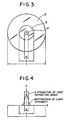
- Fig. 3 shows a horizontal cross-sectional schematic view of an optical fiber made of the preform for a single mode fiber shown in Fig. 2.
- Fig. 4 shows a diagram of both distributions of refractive index and light intensity of the single mode fiber.
- Fig. 5 shows a partially vertical cross-sectional schematic illustration of a manufacturing method for a large-sized quartz glass tube using a core drilling perforator, which is a preferred embodiment of the invention.
- Fig. 6 shows a schematic illustration of a manufacturing method for a large-sized quartz glass tube using a hot carbon drill press-in process, which is another preferred embodiment of the invention.
- Fig. 7 shows a schematic illustration of a manufacturing method for a large-scale heat-treated quartz glass tube by applying a Tool-Free Drawing Method to a primary treated quartz glass tube, which is also another preferred embodiment of the invention.
- a preform is fabricated by the process which comprises mechanically grinding outer surface or outer and inner surfaces of a cylindrical quartz glass blank with high precision, and then integrating a quartz glass tube which is finished to have an inner surface roughness of 20 ⁇ m or less with an optical fiber core glass rod using a rod-in-tube technique.
- the terms referred herein are defined below as follows:
- the quartz glass tube for use in the rod-in-tube technique is a large-sized tube from about the above mentioned large-sized quartz glass tube, and is a large -scale tube having from about 50 to 300 mm ⁇ in outer diameter made from quartz glass satisfying quality features required for clad tube of optical fibers.
- a large-diameter and thick quartz glass tube can reveal reduced dimensional error.
- the eccentricity of the optical fiber which is drawn from a large-scale preform fabricated by a rod-in-tube technique can be not only reduced, but also realized with much effectiveness a low cost mass production.
- an outer diameter or the ratio of an outer to an inner diameter is, the more precisely the optical fiber can be fabricated, because the absolute value becomes large depending on the thickness of the tube.
- the smaller an outer diameter or the ratio of an outer to an inner diameter is, the more the error increases, whereby high precision in size will be required on a reactive tube adjacent to a core for use of an MCVD method and a small-diameter and thin tube for a multi jacket.
- Figs. 1 and 2 respectively show horizontal cross -sectional views of a large-sized quartz glass tube and a large-scale quartz glass preform.
- D o represents an outer diameter and D i represents an inner diameter.
- numeral 1 represents a core glass rod, numeral 2 a cladding layer and numeral 3 a sealed large-sized quartz glass tube.
- Fig. 3 shows a horizontal cross-sectional schematic view illustrating an optical fiber, for example, a single mode fiber drawn from the above mentioned large-scale quartz glass preform.
- numeral 4 represents a core
- numeral 5 an optical cladding layer
- numeral 6 an over cladding layer
- "a” shows a core diameter (d core )
- "b” an optical cladding diameter (d cladi )
- "c” an outer diameter (d clado ) of an optical fiber i.e. 125 mm.
- the distributions of refractive index and light intensity of the resulting single mode fiber are shown in Fig. 4.
- the optical cladding portion is the part where the power of light spreads out outside the core diameter (d coreo ).
- the optical cladding diameter(d cladi ) therefore includes the cladding layer synthesized together with a core at the same time.
- the thickness of the optical cladding diameter should be varied depending on such conditions as the shape of the core refractive index distribution, the refractive index difference ( ⁇ n), use of a fiber.
- the value which multiplied actual results by safety index is usually used as the optical cladding diameter.
- the optical quartz glass core rod of the present invention signifies the quartz glass stick having an optical cladding portion of Fig. 4.
- the ratio d clado /d cladi of the outer diameter (d clado ) of the optical fiber of Fig. 3 to the optical cladding diameter (d cladi ) thereof is approximately proportional to the ratio D o /D i of the outer diameter (D i ) to the inner diameter (D i ) of the large-sized quartz glass tube of Fig.1 which fabricates the large-scale preform of Fig.2. Accordingly, it is necessary to design optical fibers according to the D o /D i as the guideline.
- D o /D i will have values as shown in Table 1.
- the power distribution of 1.3 ⁇ m band (such as matched cladded types, deplest types), 1.55 ⁇ m band and dispersion shift types is assumed to be about 20 ⁇ m or less, respectively.
- a d cladi /d core ⁇ 3 or more, i.e. D o /D i ⁇ 4.63 is utilized as practical ranges being taken account for a safety ratio.
- D o /D i also will be a lower value when the preforms are jacketed by twofold or threefold. Selecting D o /D i in the range from 1.1 to 7 is a necessary condition for fabricating a practical fiber. It is just natural that some slits between a quartz tube and a core rod must exist in the case of designing a quartz glass tube for a rod-in-tube technique, because D o /D i is the ratio of the preform.
- a pot melt pulling process and a mold shaping process may be useful.
- the heat-resistant material of a crucible is brought into direct contact with the glass melt for many hours, impurities inside the heat resistant material immigrate into the inner and outer surfaces of the quartz glass by diffusion. Such impurities are unfavorable so that they increase transmission loss of the optical fiber. Therefore, it is necessary to remove the contaminated portion of the core portion when a cladding tube is jacketed adjacent to a core portion.
- the first method consists of two steps. At the first step, a cylindrical quartz glass blank is prepared. At the second step, the blank is subjected either to mechanical drill by using a core drill as shown in Fig. 5 to make a hole at the center or it is subjected to a hot carbon drill press-in process to make a hole.
- the second method is to use the OVD method described in U.S.P.No.2,272,342 wherein a porous silica soot material is deposited on a heat resistant core material, then removing of the core, dehydration and fusing of the deposit for vitrification.
- the third method comprises forming a perforated soot material directly by the VAD method, and then fusing the dehydrated deposit for vitrification.
- numeral 7 represents a cylindrical quartz glass blank
- numeral 8 a core drill
- numeral 9 a grinding stone
- Fig. 6 shows a schematic view illustrating a hot carbon drill press-in process wherein numeral 10 represents a cylindrical quartz glass blank, numeral 11 a carbon drill, numeral 12 a quartz glass primary tube and numeral 13 a thermal heater. If an original dimensional error in thickness of the quartz glass tube for a rod-in-tube technique is so large, the heating and drawing treatment amplifies it to become relatively much larger. Since the multi-coating also expands the error, the precise dimensional adjustment is highly required. A high accuracy quartz glass primary tube made from a quartz glass mother material can be obtained by mechanical grinding.
- a quartz glass primary tube having 50 mm ⁇ or more in outer diameter and approximately 3,000 mm in length can be entirely processed into a straight tube having a cross section of high circularity. Accordingly, the surface of the resulting tube must be finished by mechanically polishing, with a grinding stone being changed or the grade of a abrasive grains being varied, in order to remove cracks, crazes, strains caused by tension or the like, subjected to HF-etching treatment to relax a concentrated tension.
- the tube is further subjected to ultra-sonic washing to remove contaminated materials from the surface, and then controlled to a roughness of 20 ⁇ m or less on the inner surface.
- the heating treatment can make the surface of the tube smoothly by relaxing a sharp roughness generated under a process of mechanical grinding, releases the strain and restricts a generation of bubbles.
- a preferred means for finishing the inner surface of the quartz glass tube is a high precision honing process either in case that a cylindrical quartz glass blank is mechanically drilled with a core dril or the like to make an opening at the center or is used a quartz glass primary tube which is obtained by roughly grinding mechanically the inner and outer surface of a large-scale tubular quartz glass blank under a process of OVD method or the like.
- the clearance between the quartz glass tube and the core glass rod can be narrowed.
- the primary tube having its inner surface ground and mechanically polished by high precision honing machine is subjected to peripheral grinding to control the thickness to achieve an error falling within 2%.
- a hot carbon drill press-in process is processed in a manner that a cylindrical quartz glass blank is heated and a carbon drill is pressed at the center of the blank.
- Employing this kind of opening method can provide advantages to easily manufacture a large-sized quartz glass tube having 20 ⁇ m, practically a few ⁇ m, or less in inner surface roughness without grinding or polishing the inner surface of the quartz glass tube. If the outer diameter of the quartz glass blank exceeds 50 mm ⁇ , then the eccentricity of its opening portion and the straightness of the tube can be remarkably improved.
- a cylindrical quartz glass blank having 50 mm ⁇ or more in outer diameter is processed to make an opening at the center under the hot carbon drill press-in process, can be achieved a straight cylindrical tube having 300 mm ⁇ or more in outer diameter and approximately 3,000 mm in length, the cross section of which reveals a high circularity at any position along its longitudinal direction.
- the grinding conditions for the outer periphery is not so strict as in the case of inner periphery because the outer periphery is heated directly from the heating zone. Nevertheless, the surface roughness of the outer periphery must be controlled to be at least 200 ⁇ m or less, preferably 100 ⁇ m or less, by HF-etching treatment to remove or to relax the portion where high tension is concentrated, because the quality thereof influences the fracture strength of the final product i.e. the optical fiber.
- well established machining methods for semiconductor ingots and various types of ceramic materials such as a standard peripheral grinding or a process using cylindrical grinder may be used.
- the mechanically processed surface is subjected under a finish polishing process to achieve the thickness error within 2% and HF-etching treatment to obtain a primary treated quartz glass tube with 20 ⁇ m or less in inner surface roughness.
- the primary treated quartz glass tube is integrated with a core glass rod for an optical fiber by applying the rod -in-tube technique thereto.
- the features of the core glass rod vary even though the rod can be produced under the same conditions depending on fiber specifications, users or manufacturing methods.
- a plurality of quartz glass tubes with different sizes can be produced by conducting heating and drawing treatment to meet the primary treated quartz glass tube with the core glass rod.
- the Tool-Free Drawing process is employed to prevent an adhesion of impurities.
- Fig. 7 shows a schematic view illustrating a Tool -Free Drawing process wherein numeral 14 represents a primary treated quartz glass, numeral 15 a heating source, numeral 16 a drawing roll, numeral 17 a dummy tube, numeral 18 a heat-treated quartz glass tube and numeral 19 a sensor.
- drawing and inner pressure must be applied.
- the pressure must be varied according to the dimension and thickness of the primary treated tube, the viscosity of the glass on heating, and the drawing ratio; to achieve the dimension with a higher precision, the process should be conducted as such that the ratio (D o /D i ) / (d o /d i ) fall in the range from 1.0 to 1.5, wherein D o and D i represent each the outer and the inner diameter of the primary treated synthetic quartz glass tube, respectively, and d o and d i represent each the outer and the inner diameter of the heat-treated tube, respectively.
- the tube may accompany deformation on heat treatment, and if the ratio exceeds 1.5, the thickness error becomes so large that the tube may cause burst depending on temperature conditions. Hence, a quartz glass tube with dimensional precision would not be expected if the ratio falls outside the defined range. In particular, if the ratio approaches 1.5, the thickness error must fall absolutely within a range of 2%.
- the heat treatment for tubes of from 50 mm to 300 mm ⁇ in diameter must be conducted in the temperature range from 1600°C to 3000°C, preferably from 1600°C to 2400°C. If the heat treatment is carried out at a temperature lower than the above defined range, the primary treated quartz glass tube cannot be sufficiently softened; if it is carried out at a temperature higher than the defined range, the primary treated tube may suffer degradation or may be fluidized. In either case, a high dimensional precision can no longer be maintained.
- the ratio D o /D i or d o /d i represents the cladding layer thickness of a single mode optical fiber. In a single jacketed optical fiber, the above ratio must be in the range of from 2 to 7; in an optical fiber with 2 or more jackets, the above ratio should be in the range of from 1.1 to 3.
- the quartz glass tube thus obtained has been heat -treated in the high temperature range from 1,600°C to 2,400 °C so that various damages, such as roughness and work distortion of the ground surface caused by mechanical grinding, can be relaxed or released.
- various damages such as roughness and work distortion of the ground surface caused by mechanical grinding
- the larger be deformed by thermal rolling, the larger grow flaws, cracks and pits on the surface so that the grooves will become shallow and loose their acute angle portions.
- the target large-sized quartz glass tube can be efficiently obtained by thermally deforming a large-sized high precision primary treated quartz glass tube.
- the manufacturing method for natural quartz glass in accordance with the present invention comprises the steps of selecting good quality portions of a clod of natural crystal glass, further picking out the central portions by removing the periphery of each crystal clods, making each particle diameters uniform by smashing the clods and removing impurities by chemical treatment after removing foreign substances. Then, thus treated material is subject to well known conventional methods, such as a pot melt pulling method or a mold shaping method which have been widely used for long time.
- the glass ingots obtained by this process are frequently used as photo mask substrates for semiconductors and as optical members for exposure devices.
- the plasma process which is a modified Verneuil process, is for producing special use articles such as high purity core glass for optical fibers, because it consumes large electric power and is hence a costly process.
- another process as an appropriate one free from the above shortcoming for manufacturing blanks in accordance with the present invention, which comprises depositing a porous soot material on a rotating substrate (target) by blowing a material gas while lowering the flame temperature, subjecting the soot material to dehydration and the like, and finally vitrifying the treated soot material.
- a VAD method provides principally a solid cylindrical quartz glass blank.
- Another one, i.e., an OVD method enables tubular glass products by direct synthesis.
- the synthetic quartz glass blank for use in the present invention preferably is produced from a porous soot material, because the OH groups and the refractive index can be controlled as desired to meet the demands depending on the cladding portion of the core glass rod to be used in the process.
- a large aperture preform having 75 mm ⁇ or less in diameter can be directly obtained not only from a quartz glass tube having approximately 75 mm ⁇ in diameter, but either to re-draw a larger preform or to directly produce the preform of the desired outer diameter by simultaneously conducting drawing with the integration of the quartz glass tube and the core glass rod in the rod-in-tube technique.
- the selection of a mode field diameter, a cut off wavelength, and a dispersion is important for a single mode core glass rod. With the recent increase in quality, it is often the case to find scattered characteristic values when the produced core glass rods are used as they are. Accordingly, it is preferred that the clad thickness of the core glass rod is first controlled before jacketing, and then applying fine adjustment by etching and the like after once preparing the rod into a preform.
- a large scale porous quartz soot material was produced by vapor phase axial deposition (VAD) method which comprises evaporating SiCl 4 ; flame hydrolyzing the SiCl 4 gas in an oxyhydrogen flame burner to produce the soot of SiO 2 ; depositing it on a rotating quartz rod.
- VAD vapor phase axial deposition
- the resulting soot material was dehydrated by heating it in a mixed gas system of He and Cl 2 inside an electric heating furnace, which was subjected to zone melting process at 1550°C to obtain a fused glass.
- zone melting process at 1550°C
- the periphery of the quartz glass ingot was roughly so as to adjust the dimention by using a peripheral grinder equipped with #80 grinding stone, after the both ends were cut, and then the center thereof was drilled with a core drill equipped also with a #80 grinding stone.
- a synthetic quartz glass primary tube about 10 kg in weight, 94 mm ⁇ in outer diameter, 30 mm ⁇ in inner diameter with an outer to inner diameter ratio of 3.13 about 32 mm in wall thickness, and 730 mm in length.
- the internal surface of the resulting primary tube was wholly machined along the length direction using an automatic long honing machine for high precision finishing to obtain a long tube having a hole with a cross section of high circularity being drilled straight along the longitudinal direction.
- the polishing degree was gradually increased by changing abrasive stones to finish with #800.
- the outer periphery of the tube was then ground using an NC peripheral grinder so that the center of the outer diameter may conform with that of the inner diameter. After it was confirmed that the tube is finished to a thickness falling within an error of 2%, the outer periphery was finished with #140.
- the tube was etched in a hydrofluoric acid cell of 5% to 30% in concentration while checking the surface. This step is necessary for removing surface strains and relaxing surface machining stress.
- a primary treated synthetic quartz glass tube was finally obtained by washing the etching-finished tube with pure water.
- the primary treated tube thus obtained was 91.5 mm ⁇ in outer diameter, 32.4 mm ⁇ in inner diameter with an outer to inner diameter ratio D o /D i of 2.82, 29.55 mm in thickness, 730 mm in length, and 9.2 kg in weight.
- the thickness error (t max. - t mini. ) was 0.48 mm (1.62%).
- the surface was examined for roughness by traveling a contact type compact roughness meter for 8 mm along the longitudinal direction to find an R max. of 4.8 ⁇ m for the inner surface and 53 ⁇ m for the outer surface.
- a 1.3- ⁇ m wavelength single mode core glass rod having a refractive index difference ( ⁇ n) of 0.343% between a core and a clad was produced by VAD method.
- This core glass rod having a dimension of 54.5 mm ⁇ in outer diameter including adhasion of the clad, and 455 mm length.
- the rod was hot drawn to an outer diameter of 30.1 mm by using an automatic precision drawing machine equipped with an outer diameter controller and designed as such to have a cut-off wave-length ⁇ c of 1. 25 ⁇ m. After slightly etching the outer surface, the rod was fuse cut at a length of 730 mm.
- the core glass rod thus obtained was then carefully inserted into the above primary treated synthetic quartz glass tube and fixed therein by matching the center thereof with that of the glass tube.
- the both ends of the resulting assembly was connected to a dummy quartz material and rotated to straighten any bends or twists.
- This assembly was then inserted into a vertical electric heating furnace from the upper side to fuse the front end at 2180 °C, and the pressure therein was reduced using a vacuum pump.
- the rod-in-tube assembly was moved under varying speed while controlling separately the temperature in the range from 2000 °C to 2400 °C and the vacuum degree in the range from 200 mm to 1000 mmAq to examine for the formation of air bubbles at the boundary.
- a preform was obtained by slowly traveling the whole at a rate of 2 mm/min so that no air bubbles might be formed. Thus, was obtained a preform under a stable condition, which was 90.2 mm in diameter, 595 mm in length, and 8.3 kg in weight. Thus, yields fibers as long as about 300 km.
- a part of the resulting preform was hot drawn to an outer diameter of about 50 mm ⁇ , and was subjected to observation using a preform analyzer.
- the step difference in refractive index at boundary between the cladding layer and the rod was not more than 0.01%, and the eccentricity was 0.153 mm (0.34%).
- the surface was examined for roughness by traveling a contact type compact roughness meter for 8 mm along the longitudinal direction to find an R max. of 8.5 ⁇ m for the inner surface and 68 ⁇ m for the outer surface.
- the primary treated synthetic quartz glass tube was then heated to 2200 C in a vertical heating furnace to weld the bottom end portion and hot drawn under pressure as shown in Fig. 6 while flowing an inert gas inside and outside the tube.
- five types of heat treated synthetic quartz glass tube were obtained as shown in Table 2.
- the internal surface roughness R max. was found to be considerably reduced after the heat treatment.
- a single mode core glass rod having a refractive index difference ( ⁇ n) of 0.335% was produced by VAD method.
- the core glass rod processed to fit each of the five heat treated synthetic quartz glass tubes shown in Table 2 as the cladding layer. Accordingly, the outer periphery of the core glass rod was etched and hot drawn to obtained each of the core glass rods shown in Table 2.
- Each of the core glass rods was inserted into the corresponding heat treated synthetic quartz glass tube to give each a rod-in-tube structure, and then welded together by heating in an electric heating furnace to give a preform. No step difference in refractive index was observed between the cladding layer and the rod upon measuring with a preform analyzer.
- a primary optical fiber 125 mm in diameter was produced from a 62-mm ⁇ diameter preform No. 3 in Table 2, and the fiber characteristics thereof were measured. It has been found as a result to be high quality optical fiber yielding a cut off wavelength ⁇ c of 1.245 ⁇ m, a transmission loss for 1.3 ⁇ m wavelength of 0.334 dB/km, and an eccentricity of 0.32 ⁇ m.
- a large porous soot material having produced by vapor phase axial deposition (VAD) method was dehydrated and vitrified in accordance with the process as described in Example 1.
- the resulting product was heat dehydrated, vitrified and roughly ground in the same manner as described in Example 1 to obtain a cylindrical quartz glass blank (ingot) about 820 mm in length and having an outer diameter of 96 mm ⁇ .
- This ingot was drilled at the center using a hot carbon drill press-in process. A higher dimensional precision was then achieved by peripheral grinding followed by etching with hydrofluoric acid solution.
- the synthetic quartz glass primary tube weighing about 11.5 kg at this point was found to have an outer and inner diameters of 101 mm ⁇ and 40 mm ⁇ , respectively, a ratio of the outer diameter to the inner diameter of 2.525 and a length of 775 mm. Because the internal surface of the tube drilled was fused by pressing-in a hot carbon drill, no defects such as cracks ascribed to mechanical impact or grinding damage, crazes, machining stress, and the like, were observed.
- a large porous soot material having produced by outside vapor-phase deposition (OVD) method was dehydrated, subjected to treatment for refractive index adjustment, and vitrified to obtain tubular synthetic quartz glass blank.
- the both peripheries of the quartz glass blank were severed and the outer surface thereof were roughly ground by using a peripheral grinder equipped with #80 grinding stone to achieve substantially the predetermined outer diameter.
- the internal surface of the resulting tube was wholly polished by using a honing machine equipped with #80 grinding stone.
- the polishing degree was gradually increased by changing grinding stones to finish with #140, #400and #800, respectively.
- treated tube was examined for thickness deviation by traveling an ultrasonic thickness meter for 50 mm along the longitudinal direction to achieve 8 measuring points around each of the circumferences.
- the error thickness thus obtained was figured by using a computer.
- the outer peripheral of the tube was then ground by using an NC peripheral grinder. After it was confirmed that the tube is finished to a thickness falling within the predetermined error, the tube was etched in a hydrofluoric acid solution.
- the large primary treated synthetic quartz glass tube thus obtained was a large sized quartz glass cylinder having an outer diameter of 164 mm ⁇ , an inner diameter of 58.9 mm ⁇ with an outer to inner diameter ratio D o /D i of 2.78, a thickness of 52.55 mm with a thickness error of 440 ⁇ m (0.84%), a length of 1,870 mm, and a weight of about 75 kg.
- This primary treated tube was found to have surface roughness R max. of 3.5 ⁇ m for the inner surface and 77 ⁇ m for the outer.
- large quartz core glass rods for single mode operation were produced by VAD method for use in combination with the primary treated synthetic quartz glass tube obtained above.
- Three rods having similar characteristics were selected from the thus produced rods.
- the core diameter necessary for the core glass rods to fit the primary treated synthetic quartz glass tube was calculated, and a part of the cladding was etched to adjust the rod diameter.
- the resulting three core glass rods were fuse joined, drawn to approximately the same outer diameter (55 mm ⁇ ), etched, and then the entire surface thereof was fire-polished.
- the core glass rod thus obtained was inserted into the large primary treated synthetic quartz glass tube and fixed.
- the assembly thus obtained was heated at the temperature range from 2000 °C to 2400 °C in a vertical electric heating furnace to fuse and soften it from the lower end, and at the same time, traveling it while controlling the temperature and the vacuum degree to a range from 200 mm to 1000 mmAq.
- An inadequate temperature or a rapid moving rate causes air bubbles to form at the internal boundary.
- the assembly was first drawn to yield a diameter of about 50 mm ⁇ in the initial step so that sufficient welding may occur at the boundary.
- the diameter of 75 mm ⁇ , 100 mm ⁇ , 125 mm ⁇ and 150 mm ⁇ thus obtaining 5 types of preforms in total.
- the five preforms finally obtained had a maximum outer diameter of 152 mm ⁇ , and they weighed about 71 kg as a whole. This was an amount corresponding to a primary optical fiber having a length of 2600 km.
- the characteristics of the resulting preform was evaluated in further detail.
- a 50 mm ⁇ diameter preform was chosen as the sample.
- the core characteristics were observed by using a preform analyser to find the preform to have no step difference but a seam with approximately 0.008% in refractive index at the boundary between the core and the cladding layer, and the center displacement of the core from the cladding layer to be 0.28%.
- the above 50 mm ⁇ preform was drawn with a optical fiber drawing machine to obtain a fiber 125 ⁇ m ⁇ 0.5 ⁇ m in outer diameter.
- the resulting primary optical fiber were found to give transmission characteristics of an eccentricity of 0.11 ⁇ m, a cut off wavelength ⁇ c of 1.270 ⁇ m, a transmission loss for 1.3 ⁇ m wavelength of 0.361 dB/km, and OH group loss for 1.38 ⁇ m wavelength of 0.65 dB/km.
- a large porous soot material having produced by outside vapor-phase deposition (OVD) method was dehydrated, subjected to treatment for refractive index adjustment, and vitrified in the same manner as in Example 4 to obtain a tubular synthetic quartz glass blank.
- the inner and the outer peripheries of the resulting product were mechanically ground to achieve 4 synthetic quartz glass primary tubes.
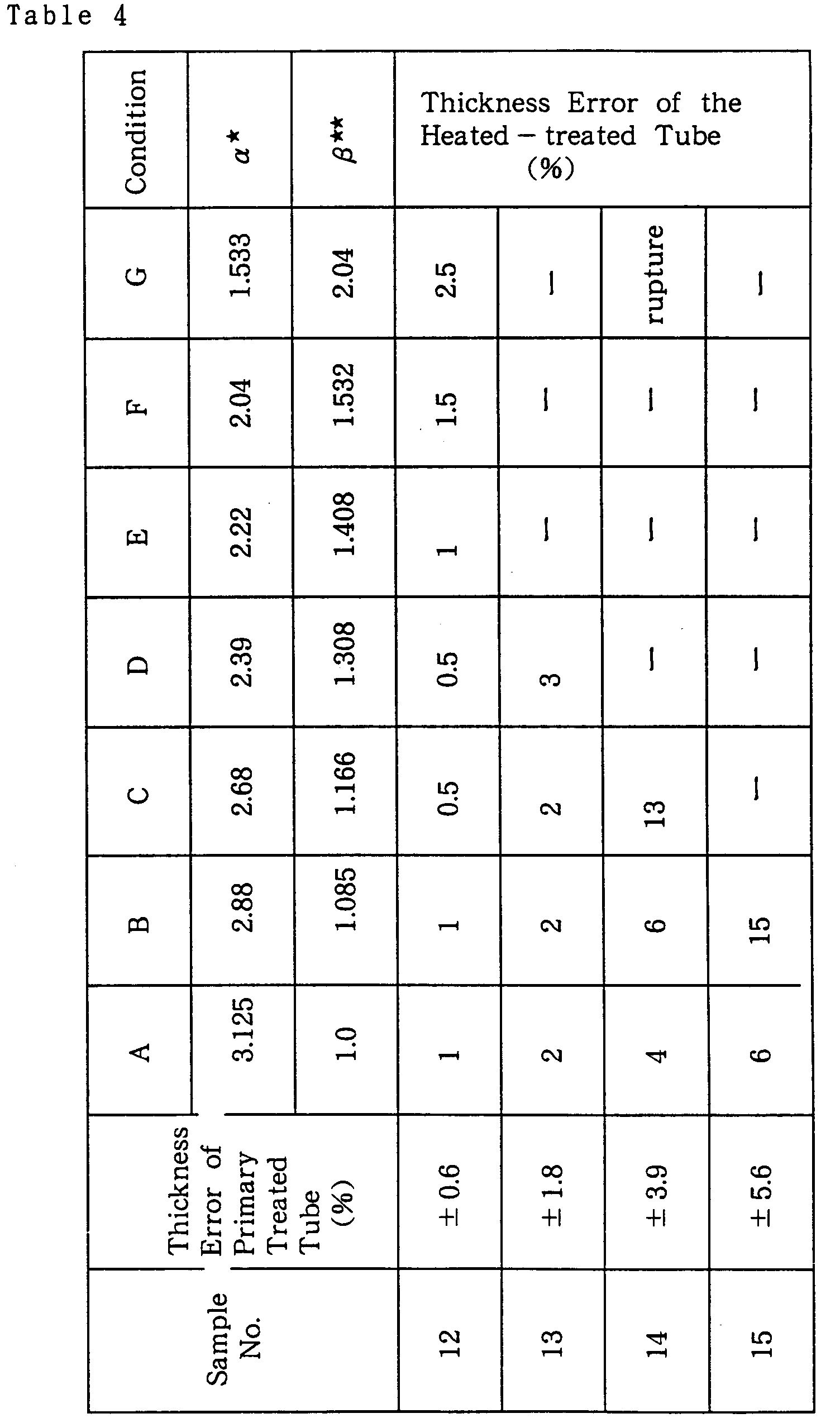
- the inner diameter of the resulting primary tube was finished with high precision honing machine to 32 mm ⁇ , the center lines for inner and outer diameters respectively were shifted artificially. Then, the outer surface was ground to an outer diameter of 100 mm ⁇ with an outer to inner diameter ratio D o /D i of 3.125. Finally, the tube was finished by etching with hydrofluoric acid solution and washing with water. The measured thickness error for the resulting primary treated synthetic quartz glass tube is shown in Table 4.
- the above primary treated synthetic quartz glass tube was drawn under the pressure range from 0 to 100 mmAq fluid and heated at 2200 °C in an electric heating furnace to examine for dimensional change caused by processing.
- a quartz glass primary treated tube with large error reveals larger error when it is treated under an increased pressure ratio and an increased drawing ratio.
- the pressure ratio directly increases the thickness error of the quartz glass tube.
- the primary treated tube with error more than 3.9% was deformed asymmetrically under unstabilized conditions at the beginning and expanded rapidly into rupture in the furnace.
- An optical fiber core glass rod was inserted into one (No.13) of the heat-treated synthetic quartz glass tubes fabricated above under condition B, i.e., a quartz glass tube obtained from a primary treated tube having a thickness error within 1.8% and finished to a thickness error within 2% by hot drawing under pressure.
- a preform was obtained therefrom by a rod-in-tube technique. This preform was found that a difference in refractive index between the cladding layer and the rod was as low as 0.01% or less, and an eccentricity after drawing of 0.45 ⁇ m upon evaluation with a preform analyzer. It can be seen, therefore, that the preform can be favorably used as a single mode use optical fiber.
- a large-scale cylindrical natural quartz glass blank produced by the Verneuil process using an oxyhydrogen flame was drilled at the center using a hot carbon drill press-in process in the same manner as in Example 3.
- the outer periphery of the resulting product was mechanically ground and finished followed by etching with hydrofluoric acid solution, by washing with water and drying to obtain a primary treated quartz glass tube having the outer diameter of 175 mm ⁇ , the inner diameter of 60 mm ⁇ , the ratio of the outer to the inner diameter of 2.916, the length of 3 m and the weight of 150 kg.
- the average thickness error along the longitudinal direction at each of 50 mm interval points reveals 0.3 mm which falls into the predetermined error range.
- a single mode optical fiber rod having a cladding partially for use of 1.3 ⁇ m wave length produced by VAD method was inserted into the aforementioned primary treated quartz glass tube and disposed in a vertical type electric furnace. The end of portions of the rod were welded at the temperature of 2250 °C in a reduced atmosphere pressure.
- the rod-in tube process was conducted to obtain a preform having a maximum outerdiameter of 160 mm ⁇ under conditions wherein the degree of vacuum and the initial drawn outer diameter are set to be 200 mm to 1000 mmAq and 50 mm ⁇ , respectively, and the temperature, the traveling speed and the degree of vacuum were changed depending on the fused state at the boundary between the core rod and the primary treated quartz glass tube.
- the above treated preform drawn initially with 50 mm ⁇ in diameter examined by a preform analyzer shows 0.52% in eccentricity and approximately -0.005% in refractive index difference with slightly lower index of the tube.
- the above preform is drawn by a drawing machine to have an optical fiber of 125 ⁇ m in diameter revealing 0.41 ⁇ m in eccentricity and 0.346 dB/km in transmission loss at 1.3 ⁇ m wave length. It can be considered, therefore, that the preform can be favorably used as single mode use optical fiber.
- a cylindrical quartz glass blank made from high purity natural quartz glass was drilled at the center by using a hot carbon drill press-in process in the same manner as in Example 6.
- treated quartz glass tube having the outer diameter of 150 mm ⁇ , the inner diameter of 62 mm ⁇ , the outer to the inner diameter ratio of 2.42 and the length of 2,500 mm, was measured along the longitudinal direction at each of 50 mm interval points to show 0.35 mm (0.79%) in thickness error, less than 1 ⁇ m in roughness R max. of the inner surface and 85 ⁇ m in roughness R max. of the outer surface.
- the above quartz glass was proved to contain an OH group with 166 ppm in average by inspecting its 2.7 ⁇ m absorption band by an infrared spectrophotometer.
- the above quartz glass tube was disposed in a vertical type electric furnace having 2250 °C in temperature to weld the bottom end portion of the tube. Drawing was conducted under pressure controlled by air from the upper end portion to obtain the heat treated quartz glass tube having 50 mm ⁇ , 75 mm ⁇ and 125 mm ⁇ in outer diameter, respectively.
Landscapes
- Engineering & Computer Science (AREA)
- Chemical & Material Sciences (AREA)
- Materials Engineering (AREA)
- Organic Chemistry (AREA)
- Life Sciences & Earth Sciences (AREA)
- General Life Sciences & Earth Sciences (AREA)
- Geochemistry & Mineralogy (AREA)
- Manufacturing & Machinery (AREA)
- Mechanical Engineering (AREA)
- Mining & Mineral Resources (AREA)
- Manufacture, Treatment Of Glass Fibers (AREA)
- Glass Melting And Manufacturing (AREA)
Description


| Sample No. | 7 | 8 | 9 | 10 | 11 |
| Abrasives | None | # 800 | # 400 | # 140 | # 80 |
| Roughness after Etching (Rmax.) (µm) | <1.2 | 4.5 | 16.4 | 26 | 68 |
| State of Boundary | No bubbles | No bubbles | Few bubbles | Fine bubbles | Various bubbles |

Claims (7)
- A method for manufacturing a large-sized quartz glass tube comprising steps ofa) providing a quartz glass primary tube by drilling a cylindrical quartz glass ingot or by producing a tubular quartz glass blank,b) grinding, abrading and finishing inner and outer surfaces of the quartz glass primary tube,c) etching the surfaces with hydrofluoric acid andd) washing
to obtain a large-sized primary treated quartz glass tube, havingandaa) an outer diameter (Do) falling in a range from 50 mm ⊘ to 300 mm ⊘;bb) an outer to inner diameter ratio (Do / Di) falling in a range from 1.1 to 7;cc) a wall thickness of 10 mm or more;dd) a wall thickness error of 2 % or less; andee) a roughness of an inner surface of 20 µm or less,e) thermally deforming the primary treated quartz glass tube bye1) heating ande2) hot drawing or hot drawing under pressure. - Method according to claim 1, wherein hot drawing under pressure comprisestool-free drawing of the primary treated quartz glass tube in a temperature range from 1600 °C to 3000 °C and under control of the pressure inside the primary treated quartz glass tube which has an outer diameter Do and an inner diameter Di,resulting in a heat-treated quartz glass tube having an outer diameter do and an inner diameter di, whereby the following equation is satisfied:
- Method according to claim 1, wherein for drilling a drilling machine, and for grinding, abrading and finishing inner and outer surfaces both a peripheral grinder and a high precision honing machine are used.
- Method according to claim 1, wherein the cylindrical ingot is drilled by a hot carbon drill press-in process.
- Method for manufacturing a large-scale quartz glass preform bya) providing a quartz glass primary tube by drilling a quartz glass cylindrical ingot or by producing a tubular quartz glass blank,b) grinding, abrading and finishing inner and outer surfaces of the quartz glass primary tube,c) etching the surfaces with hydrofluoric acid andd) washing
to obtain a large-sized primary treated quartz glass tube, havingaa) an outer diameter (Do) falling in a range from 50 mm ⊘ to 300 mm ⊘;bb) an outer to inner diameter ratio (Do / Di) falling in a range from 1.1 to 7;cc) a wall thickness of 10 mm or more;dd) a wall thickness error of 2 % or less; andee) a roughness of an inner surface of 20 µm or less,e) thermally deforming the primary treated quartz glass tube byande1) heating ande2) hot drawing or hot drawing under pressuref) inserting a core glass rod for an optical fiber into the quartz glass tube and welding the rod and the tube using the rod-in-tube technique. - Method according to claim 5, wherein welding of the rod and the tube by using the rod-in-tube technique according to step f) and hot drawing or hot drawing under pressure of the tube according to step e2) are simultaneously performed.
- Method for manufacturing an optical fiber by drawing from a large-scale quartz glass preform, manufactured bya) providing a quartz glass primary tube by drilling a quartz glass cylindrical ingot or by producing a tubular quartz glass blank,b) grinding, abrading and finishing inner and outer surfaces of the quartz glass primary tube,c) etching the surfaces with hydrofluoric acid andd) washing
to obtain a large-sized primary treated quartz glass tube, havingaa) an outer diameter (Do) falling in a range from 50 mm ⊘ to 300 mm ⊘;bb) an outer to inner diameter ratio (Do / Di) falling in a range from 1.1 to 7;cc) a wall thickness of 10 mm or more;dd) a wall thickness error of 2 % or less; andee) a roughness of an inner surface of 20 µm or less,e) thermally deforming the primary treated quartz glass tube byande1) heating ande2) hot drawing or hot drawing under pressuref) inserting a core glass rod for an optical fiber into the quartz glass tube and welding the rod and the tube using the rod-in-tube technique.
Applications Claiming Priority (8)
| Application Number | Priority Date | Filing Date | Title |
|---|---|---|---|
| JP33220392 | 1992-11-19 | ||
| JP332203/92 | 1992-11-19 | ||
| JP226670/93 | 1993-08-20 | ||
| JP226671/93 | 1993-08-20 | ||
| JP226669/93 | 1993-08-20 | ||
| JP22667193 | 1993-08-20 | ||
| JP22666993 | 1993-08-20 | ||
| JP22667093 | 1993-08-20 |
Publications (3)
| Publication Number | Publication Date |
|---|---|
| EP0598349A2 EP0598349A2 (en) | 1994-05-25 |
| EP0598349A3 EP0598349A3 (en) | 1994-07-06 |
| EP0598349B1 true EP0598349B1 (en) | 1998-07-29 |
Family
ID=27477231
Family Applications (1)
| Application Number | Title | Priority Date | Filing Date |
|---|---|---|---|
| EP93118316A Expired - Lifetime EP0598349B1 (en) | 1992-11-19 | 1993-11-12 | Process for manufacturing a large sized quartz glass tube, a preform and an optical fiber |
Country Status (10)
| Country | Link |
|---|---|
| US (2) | US5837334A (en) |
| EP (1) | EP0598349B1 (en) |
| KR (1) | KR0133027B1 (en) |
| CN (1) | CN1042825C (en) |
| DE (1) | DE69319999T2 (en) |
| DK (1) | DK0598349T3 (en) |
| ES (1) | ES2120467T3 (en) |
| FI (1) | FI103038B1 (en) |
| RU (1) | RU2096355C1 (en) |
| WO (1) | WO1994011317A2 (en) |
Cited By (2)
| Publication number | Priority date | Publication date | Assignee | Title |
|---|---|---|---|---|
| DE10117153C1 (en) * | 2001-04-05 | 2002-06-13 | Heraeus Quarzglas | Production of quartz glass cylinders comprises temporarily holding open the lower end of the cylinder during the attracting phase, and producing a gas window in the region of the open lower end whilst a gas stream is fed into the inner bore |
| CN102515507A (en) * | 2011-12-08 | 2012-06-27 | 华中科技大学 | Metal core microstructure fiber and preparation method thereof |
Families Citing this family (104)
| Publication number | Priority date | Publication date | Assignee | Title |
|---|---|---|---|---|
| US6138476A (en) * | 1995-06-26 | 2000-10-31 | Sumitomo Electric Industries, Ltd. | Method of producing an optical fiber coupling member |
| KR0184481B1 (en) * | 1996-06-10 | 1999-05-15 | 김광호 | High productivity optical fiber drawing device of optical fiber manufacturing device and its drawing method |
| DE19810132C2 (en) * | 1997-03-10 | 2002-02-07 | Samsung Electronics Co Ltd | Device and method for producing a tubular glass monolith using a sol-gel process |
| US5897679A (en) * | 1997-08-27 | 1999-04-27 | Lucent Technologies Inc. | Dimensional control in the manufacture of optical fiber ferrule connectors by etching |
| WO1999040037A1 (en) * | 1998-02-03 | 1999-08-12 | Sumitomo Electric Industries, Ltd. | Method of manufacturing optical fiber base material |
| CA2332123A1 (en) * | 1998-05-29 | 1999-12-02 | George E. Berkey | Method of making a glass preform |
| US6383404B1 (en) | 1998-08-19 | 2002-05-07 | Hoya Corporation | Glass substrate for magnetic recording medium, magnetic recording medium, and method of manufacturing the same |
| EP1000908B1 (en) * | 1998-10-08 | 2005-12-28 | Heraeus Tenevo GmbH | Method for producing quartz glass preform for optical fibers and the quartz glass tube used thereto |
| JP3819614B2 (en) * | 1998-10-16 | 2006-09-13 | 信越石英株式会社 | Method for producing quartz glass preform for optical fiber |
| DE59902297D1 (en) * | 1998-10-28 | 2002-09-12 | Schott Glas | QUARTZ GLASS PANELS HIGH REFRIGERATION HOMOGENITY |
| DE19852704A1 (en) * | 1998-11-16 | 2000-05-18 | Heraeus Quarzglas | Method for producing a preform for an optical fiber and substrate tube suitable for carrying out the method |
| DE19856892C2 (en) * | 1998-12-10 | 2001-03-15 | Heraeus Quarzglas | Process for the production of a tube made of glassy material, in particular quartz glass |
| DE19915509C1 (en) * | 1999-04-07 | 2000-06-08 | Heraeus Quarzglas | Production of a cylindrical component made of quartz glass has a flue with guiding elements arranged behind each other along the pulling axis |
| DE19927788C2 (en) * | 1999-06-18 | 2003-03-06 | Forschungszentrum Juelich Gmbh | Polarizer for the polarization of an inert gas |
| DE19952821B4 (en) * | 1999-11-02 | 2004-05-06 | Heraeus Tenevo Ag | Process for producing a quartz glass preform for optical fibers |
| DE19958289C1 (en) * | 1999-12-03 | 2001-06-13 | Heraeus Quarzglas | Process for the production of a quartz glass rod and use thereof for the production of a preform |
| KR100418426B1 (en) * | 2000-05-01 | 2004-02-11 | 신에쯔 세끼에이 가부시키가이샤 | Method for measuring concentration of micro amount of oh group comprising in quarte glass |
| US6553790B1 (en) * | 2000-05-09 | 2003-04-29 | Fitel Usa Corp. | Process for fabricating optical fiber involving tuning of core diameter profile |
| DE10025176A1 (en) * | 2000-05-24 | 2001-12-06 | Heraeus Quarzglas | Process for the production of an optical fiber and preform for an optical fiber |
| JP5093956B2 (en) * | 2000-06-09 | 2012-12-12 | ヘレウス・テネボ・ゲゼルシャフト・ミット・ベシュレンクテル・ハフツング | Manufacturing method of quartz glass solid cylinder |
| US6739155B1 (en) * | 2000-08-10 | 2004-05-25 | General Electric Company | Quartz making an elongated fused quartz article using a furnace with metal-lined walls |
| DE10044715C1 (en) * | 2000-09-08 | 2001-12-06 | Heraeus Quarzglas | Production of a quartz glass tube comprises using a drilling body having a drill head having a contact surface with a convex curvature facing the quartz cylinder continuously rotating in a heating zone |
| DE10052072B4 (en) * | 2000-10-19 | 2005-06-16 | Heraeus Tenevo Ag | Method for processing an elongated hollow cylindrical component made of quartz glass by means of laser radiation |
| US6598429B1 (en) | 2000-11-17 | 2003-07-29 | Beamtek, Inc. | Method for fabricating gradient-index rods and rod arrays |
| US20020083740A1 (en) * | 2000-12-29 | 2002-07-04 | Pandelisev Kiril A. | Process and apparatus for production of silica grain having desired properties and their fiber optic and semiconductor application |
| US7797966B2 (en) * | 2000-12-29 | 2010-09-21 | Single Crystal Technologies, Inc. | Hot substrate deposition of fused silica |
| US20020083739A1 (en) * | 2000-12-29 | 2002-07-04 | Pandelisev Kiril A. | Hot substrate deposition fiber optic preforms and preform components process and apparatus |
| JP2002234750A (en) * | 2001-02-01 | 2002-08-23 | Shinetsu Quartz Prod Co Ltd | Method for producing quartz glass preform for optical fiber |
| JP4759816B2 (en) * | 2001-02-21 | 2011-08-31 | 住友電気工業株式会社 | Optical fiber manufacturing method |
| JP2002296438A (en) | 2001-03-29 | 2002-10-09 | Fujikura Ltd | Polarization-maintaining optical fiber and method of manufacturing base material thereof |
| WO2002088808A1 (en) * | 2001-04-30 | 2002-11-07 | Infineon Technologies Ag | Arrangement for multiplexing and/or demultiplexing the signals of at least two optical wavelength channels |
| US6687445B2 (en) * | 2001-06-25 | 2004-02-03 | Nufern | Double-clad optical fiber for lasers and amplifiers |
| DE10155134C1 (en) * | 2001-11-12 | 2002-12-19 | Heraeus Tenevo Ag | Single mode optical fiber preform production involves making core and first mantle layer with given diameter ratio, depositing silica soot by heating silicon compound in hydrogen-free zone containing oxygen and vitrification |
| KR20040077449A (en) * | 2002-01-17 | 2004-09-04 | 스미토모덴키고교가부시키가이샤 | Method and device for manufacturing glass tube |
| JP2003212581A (en) * | 2002-01-21 | 2003-07-30 | Sumitomo Electric Ind Ltd | Manufacturing method of polarization maintaining fiber |
| KR20040078640A (en) | 2002-01-30 | 2004-09-10 | 스미토모 덴키 고교 가부시키가이샤 | Method and apparatus for manufacturing glass tube |
| AU2003210420A1 (en) | 2002-03-22 | 2003-10-08 | Heraeus Tenevo Ag | Method for producing an optical fiber and optical fiber |
| DE10214029C2 (en) * | 2002-03-22 | 2003-09-18 | Heraeus Tenevo Ag | Method for producing an optical fiber and optical fiber produced by the method |
| WO2003095379A1 (en) * | 2002-05-09 | 2003-11-20 | The Furukawa Electric Co., Ltd. | Method of manufacturing optical fiber |
| WO2004016556A1 (en) * | 2002-08-12 | 2004-02-26 | Sumitomo Electric Industries, Ltd. | Method of producing higher-purity glass element, high-purity glass element, and production method and device for glass tube |
| US20040065119A1 (en) * | 2002-10-02 | 2004-04-08 | Fitel U.S.A. Corporation | Apparatus and method for reducing end effect of an optical fiber preform |
| US20040144133A1 (en) * | 2003-01-23 | 2004-07-29 | Fletcher Joseph Patrick | Methods for joining glass preforms in optical fiber manufacturing |
| US7021083B2 (en) * | 2003-01-29 | 2006-04-04 | Fitel Usa Corp. | Manufacture of high purity glass tubes |
| JP2004243433A (en) * | 2003-02-12 | 2004-09-02 | Shinetsu Quartz Prod Co Ltd | Method for polishing inner surface of tubular brittle material and tubular brittle material obtained by the polishing method |
| DE10393680B4 (en) * | 2003-03-21 | 2009-03-26 | Heraeus Quarzglas Gmbh & Co. Kg | Synthetic quartz glass tube for the manufacture of a preform, process for its manufacture in a vertical drawing process and use of the tube |
| CN100351192C (en) * | 2003-03-21 | 2007-11-28 | 赫罗伊斯·坦尼沃有限责任公司 | Synthetic silica glass tube for the production of a preform, method for producing the same in a vertical drawing process and use of said tube |
| JP4014045B2 (en) * | 2003-04-16 | 2007-11-28 | 信越化学工業株式会社 | Manufacturing method of glass rod |
| WO2004101456A1 (en) * | 2003-05-19 | 2004-11-25 | Sumitomo Electric Industries, Ltd | Optical fiber and method of producing the same |
| DE10325539A1 (en) * | 2003-06-04 | 2004-01-08 | Heraeus Tenevo Ag | Quartz glass cylinder for the production of an optical component and method for its production |
| DE10325538A1 (en) * | 2003-06-04 | 2004-01-22 | Heraeus Tenevo Ag | Method for producing an optical component from quartz glass by elongating a coaxial arrangement and optical component produced according to the method |
| JP4206850B2 (en) * | 2003-07-18 | 2009-01-14 | 信越化学工業株式会社 | Manufacturing method of large synthetic quartz glass substrate for exposure |
| US20050097923A1 (en) * | 2003-11-12 | 2005-05-12 | General Electric Company | System and support rod assembly for sintering fiber optic sleeve tubes |
| DE10357063B3 (en) * | 2003-12-04 | 2005-04-21 | Heraeus Tenevo Ag | Vertical drawing of glass, comprises continuously supplying a glass cylinder containing a vertical heating tube to a heating zone, softening, drawing and cutting |
| FR2863606B1 (en) * | 2003-12-15 | 2007-06-01 | Cit Alcatel | METHOD OF MAKING AN OPTICAL FIBER OPTIC PREFORM, OPTICAL FIBER PREFORM AND OPTICAL FIBER THEREFOR |
| US7395679B2 (en) * | 2004-03-19 | 2008-07-08 | Konica Minolta Opto, Inc. | Method of manufacturing glass substrate for information recording medium |
| CN102583997B (en) * | 2004-11-29 | 2015-03-11 | 古河电气工业株式会社 | Optical fiber preform, method of manufacturing optical fiber preform, and method of manufacturing optical fiber |
| DE102004059804B4 (en) * | 2004-12-10 | 2006-11-09 | Heraeus Tenevo Gmbh | A method for producing a quartz glass hollow cylinder as a raw material for an optical preform or for an optical fiber and use |
| DE102004060408B4 (en) * | 2004-12-14 | 2007-08-16 | Schott Ag | Apparatus and method for producing a glass tube |
| DE102005028219B3 (en) * | 2005-05-16 | 2006-10-12 | Heraeus Tenevo Gmbh | Quartz glass tube, is produced by elongating a hollow glass cylinder by continuously feeding it to a heating zone with a vertical heating tube |
| JP2007063094A (en) * | 2005-09-01 | 2007-03-15 | Sumitomo Electric Ind Ltd | Quartz tube inner surface processing method, optical fiber preform manufacturing method, and optical fiber manufacturing method |
| DE102007022272B4 (en) * | 2007-05-09 | 2016-06-02 | Heraeus Quarzglas Gmbh & Co. Kg | A method of manufacturing a quartz glass tube by elongating a quartz glass hollow cylinder |
| DE102008016230A1 (en) | 2008-03-27 | 2009-05-20 | Heraeus Quarzglas Gmbh & Co. Kg | Production of synthetic quartz glass cylinders comprises forming coating of silica granules on quartz glass cylinder and sintering it, granules having multimodal particle size distribution with maxima in specified ranges |
| CN101643310B (en) * | 2009-09-03 | 2011-03-02 | 成士林 | Continuous smelting one-step method for producing overlarge-caliber high-temperature deformation resistant quartz glass tube |
| US8192702B2 (en) * | 2010-02-01 | 2012-06-05 | Norell, Inc. | Sample tubes for use in automated systems and methods of manufacture |
| CN101811819B (en) * | 2010-04-16 | 2011-11-16 | 李秀山 | Mold for manufacturing large-caliber glass tubes and method for manufacturing glass tubes by using mold |
| CN102199000B (en) * | 2011-03-30 | 2012-08-08 | 连云港福东正佑照明电器有限公司 | Double-wall quartz glass tube used for growth of gallium arsenide crystal and preparation method thereof |
| US8936401B2 (en) * | 2011-08-30 | 2015-01-20 | Claude Belleville | Method for disposable guidewire optical connection |
| US9405078B2 (en) | 2011-08-30 | 2016-08-02 | Opsens Inc. | Method for disposable guidewire optical connection |
| DE102012006410B4 (en) * | 2012-03-30 | 2013-11-28 | Heraeus Quarzglas Gmbh & Co. Kg | Process for producing a quartz glass hollow cylinder |
| CN102981221B (en) * | 2012-12-03 | 2015-02-18 | 连云港市盛昌照明电器有限公司 | Method for manufacturing sleeve for optical fiber connector |
| DE102013107435B4 (en) * | 2013-07-12 | 2015-01-29 | Heraeus Quarzglas Gmbh & Co. Kg | Method for producing a quartz glass large tube |
| US10384972B2 (en) * | 2014-02-06 | 2019-08-20 | Momentive Performance Materials Inc. | Fused quartz tubing for pharmaceutical packaging and methods for making the same |
| JP6402466B2 (en) * | 2014-03-31 | 2018-10-10 | 住友電気工業株式会社 | Multi-core optical fiber manufacturing method |
| JP6385472B2 (en) | 2014-06-17 | 2018-09-05 | ヘレーウス クオーツ ノース アメリカ エルエルシーHeraeus Quartz North America LLC | Apparatus and method for measuring transparent cylindrical products |
| CN105891951A (en) * | 2014-09-30 | 2016-08-24 | 中国兵器装备研究院 | Modularized manufacturing method of multi-core beam combiner |
| CN107406296B (en) | 2015-06-02 | 2022-01-25 | 贺利氏石英北美有限责任公司 | Method for inserting a core rod into an overclad tube with spacers |
| EP3112323B1 (en) * | 2015-07-03 | 2021-09-01 | Heraeus Quarzglas GmbH & Co. KG | Method for producing a substrate pipe made of quartz glass |
| US10618833B2 (en) | 2015-12-18 | 2020-04-14 | Heraeus Quarzglas Gmbh & Co. Kg | Preparation of a synthetic quartz glass grain |
| TWI788278B (en) | 2015-12-18 | 2023-01-01 | 德商何瑞斯廓格拉斯公司 | Glass fibres and pre-forms made of homogeneous quartz glass |
| CN108698880B (en) | 2015-12-18 | 2023-05-02 | 贺利氏石英玻璃有限两合公司 | Preparation of opaque quartz glass bodies |
| JP6940235B2 (en) | 2015-12-18 | 2021-09-22 | ヘレウス クワルツグラス ゲーエムベーハー ウント コンパニー カーゲー | Preparation of quartz glass in a melting crucible of refractory metal |
| JP6981710B2 (en) | 2015-12-18 | 2021-12-17 | ヘレウス クワルツグラス ゲーエムベーハー ウント コンパニー カーゲー | Preparation of Fused Quartz from Silicon Dioxide Granules |
| JP7044454B2 (en) | 2015-12-18 | 2022-03-30 | ヘレウス クワルツグラス ゲーエムベーハー ウント コンパニー カーゲー | Preparation of carbon-doped silicon dioxide granules as an intermediate in the preparation of quartz glass |
| CN108698883A (en) | 2015-12-18 | 2018-10-23 | 贺利氏石英玻璃有限两合公司 | Spray Granulation of Silica in Quartz Glass Preparation |
| TWI813534B (en) | 2015-12-18 | 2023-09-01 | 德商何瑞斯廓格拉斯公司 | Preparation of quartz glass bodies with dew point monitoring in the melting oven |
| TW201736290A (en) * | 2015-12-18 | 2017-10-16 | 何瑞斯廓格拉斯公司 | Preparation and post-treatment of a quartz glass body |
| EP3390293B1 (en) | 2015-12-18 | 2023-04-19 | Heraeus Quarzglas GmbH & Co. KG | Increasing the silicon content in the production of quartz glass |
| TW201731782A (en) | 2015-12-18 | 2017-09-16 | 何瑞斯廓格拉斯公司 | Preparation of a quartz glass body in a multi-chamber oven |
| EP3243804B1 (en) * | 2016-05-03 | 2020-07-15 | Heraeus Quartz North America LLC | Elongation method for producing an optical glass component |
| US10450214B2 (en) | 2016-06-10 | 2019-10-22 | Corning Incorporated | High optical quality glass tubing and method of making |
| US11237323B2 (en) * | 2017-02-28 | 2022-02-01 | Corning Incorporated | Methods and systems for controlling air flow through an annealing furnace during optical fiber production |
| WO2019168054A1 (en) | 2018-02-28 | 2019-09-06 | 古河電気工業株式会社 | Multicore fiber and manufacturing method therefor, and optical transmission system and optical transmission method |
| JP6987021B2 (en) | 2018-05-28 | 2021-12-22 | 東京エレクトロン株式会社 | Plasma processing equipment and plasma processing method |
| CN108793692B (en) * | 2018-06-19 | 2021-04-23 | 江苏省晶瑞石英工业开发研究院有限公司 | A kind of method of gas refining quartz glass self-shaping |
| EP3636607B1 (en) * | 2018-10-09 | 2021-01-13 | Heraeus Quarzglas GmbH & Co. KG | Method for manufacturing a capillary tube |
| CN110028235B (en) * | 2019-03-01 | 2020-09-08 | 江苏永鼎股份有限公司 | Optical fiber preform based on continuous melting quartz sleeve and manufacturing method thereof |
| EP3766840B1 (en) * | 2019-07-17 | 2024-11-20 | Heraeus Quarzglas GmbH & Co. KG | Method for producing a hollow core fibre and for producing a preform for a hollow core fibre |
| RU2764064C1 (en) * | 2020-10-02 | 2022-01-13 | Акционерное общество «Обнинское научно-производственное предприятие «Технология» им. А.Г.Ромашина» | Method for mechanical processing of large-sized complex ceramic products |
| EP4067315B1 (en) * | 2021-03-29 | 2025-03-12 | Heraeus Quarzglas GmbH & Co. KG | Quartz glass tube and method of manufacturing the same |
| CN113213748B (en) * | 2021-04-28 | 2022-05-06 | 中国科学院西安光学精密机械研究所 | A kind of preparation method of high-strength silica fiber |
| CN114918741A (en) * | 2022-03-17 | 2022-08-19 | 无锡海力自控工程有限公司 | Monocrystalline silicon ultrathin-wall tube processing technology |
| CN114634306A (en) * | 2022-03-17 | 2022-06-17 | 深圳市比洋互联科技有限公司 | Preparation method of four-fiber tubule |
| EP4737405A1 (en) | 2024-10-31 | 2026-05-06 | Heraeus Quarzglas GmbH & Co. KG | Capillary production from hollow cylinders |
| WO2026093466A1 (en) | 2024-10-31 | 2026-05-07 | Heraeus Quarzglas Gmbh & Co. Kg | Producing capillaries from cylinders |
Family Cites Families (30)
| Publication number | Priority date | Publication date | Assignee | Title |
|---|---|---|---|---|
| US2106744A (en) * | 1934-03-19 | 1938-02-01 | Corning Glass Works | Treated borosilicate glass |
| US2272342A (en) * | 1934-08-27 | 1942-02-10 | Corning Glass Works | Method of making a transparent article of silica |
| US3455666A (en) * | 1966-05-06 | 1969-07-15 | American Optical Corp | Method of making laser components |
| US3659915A (en) * | 1970-05-11 | 1972-05-02 | Corning Glass Works | Fused silica optical waveguide |
| US3711262A (en) * | 1970-05-11 | 1973-01-16 | Corning Glass Works | Method of producing optical waveguide fibers |
| US4217027A (en) * | 1974-02-22 | 1980-08-12 | Bell Telephone Laboratories, Incorporated | Optical fiber fabrication and resulting product |
| US3932162A (en) * | 1974-06-21 | 1976-01-13 | Corning Glass Works | Method of making glass optical waveguide |
| DE2536456C2 (en) * | 1975-08-16 | 1981-02-05 | Heraeus Quarzschmelze Gmbh, 6450 Hanau | Semi-finished product for the production of optical fibers and process for the production of the semi-finished product |
| JPS59456B2 (en) * | 1976-01-29 | 1984-01-06 | 日本電信電話株式会社 | Manufacturing method of optical glass fiber |
| JPS52134623A (en) * | 1976-05-06 | 1977-11-11 | Nippon Telegraph & Telephone | Process for preparing silica glass tube |
| JPS53144758A (en) * | 1977-05-23 | 1978-12-16 | Sumitomo Electric Ind Ltd | Production of glass fibers for optical transmission |
| JPS5529020A (en) * | 1978-08-17 | 1980-03-01 | Yoshiki Maeda | Sea water moving device using ebb and flow of tide |
| JPS5617932A (en) * | 1979-07-18 | 1981-02-20 | Toshiba Ceramics Co Ltd | Transparent quartz glass pipe for optical fiber |
| JPS603014B2 (en) * | 1979-07-20 | 1985-01-25 | 三菱マテリアル株式会社 | Manufacturing method of quartz glass tube with high axial symmetry |
| JPS5637235A (en) * | 1979-09-05 | 1981-04-10 | Toshiba Ceramics Co Ltd | Thick-walled transparent quartz glass tube of high accuracy |
| GB2109367B (en) * | 1981-11-17 | 1985-02-13 | Pirelli General Plc | Manufacture of a preform for optical fibres by the rod in tube method |
| NL8201453A (en) * | 1982-04-06 | 1983-11-01 | Philips Nv | METHOD FOR MANUFACTURING OPTICAL FIBERS |
| JPS58213652A (en) * | 1982-06-04 | 1983-12-12 | Nippon Telegr & Teleph Corp <Ntt> | Method for treating surface of optical glass rod |
| US4596589A (en) * | 1984-02-09 | 1986-06-24 | Perry Gregory A | Method for producing a single mode fiber preform |
| JPS61201633A (en) * | 1985-03-04 | 1986-09-06 | Sumitomo Electric Ind Ltd | Multi-core optical fiber manufacturing method |
| JPS62275035A (en) * | 1985-05-07 | 1987-11-30 | Sumitomo Electric Ind Ltd | Production of base material for optical fiber |
| US4820322A (en) * | 1986-04-28 | 1989-04-11 | American Telephone And Telegraph Company At&T Bell Laboratories | Method of and apparatus for overcladding a glass rod |
| NL8601830A (en) * | 1986-07-14 | 1988-02-01 | Philips Nv | METHOD FOR MANUFACTURING OPTICAL FIBERS WITH A CORE AND GLASS COATING USING THE BAR IN TUBE TECHNOLOGY |
| US4882209A (en) * | 1986-09-11 | 1989-11-21 | Asahi Glass Company, Ltd. | Glass capillary tube and method for its production |
| DE3731604A1 (en) * | 1987-09-19 | 1989-03-30 | Philips Patentverwaltung | METHOD FOR PRODUCING A MONOMODE LIGHT FIBER |
| DE3921086A1 (en) * | 1989-06-28 | 1991-01-03 | Kabelmetal Electro Gmbh | METHOD FOR THE PRODUCTION OF LIGHT-WAVE GUIDES WITH MELTING OF A TUBE PIPE ONTO A RAW PREFORM |
| JPH0380124A (en) * | 1989-08-22 | 1991-04-04 | Nippon Electric Glass Co Ltd | Method for cleaning inside of glass pipe for optical fiber |
| JP3263789B2 (en) * | 1992-04-08 | 2002-03-11 | ソニー株式会社 | Imaging device |
| JP3064741B2 (en) * | 1993-05-14 | 2000-07-12 | 富士通株式会社 | Paper sheet identification device |
| JPH103924A (en) * | 1996-04-19 | 1998-01-06 | Daikin Ind Ltd | Positive electrode active material, battery using the positive electrode active material, and method for manufacturing battery |
-
1993
- 1993-11-12 EP EP93118316A patent/EP0598349B1/en not_active Expired - Lifetime
- 1993-11-12 DE DE69319999T patent/DE69319999T2/en not_active Expired - Lifetime
- 1993-11-12 ES ES93118316T patent/ES2120467T3/en not_active Expired - Lifetime
- 1993-11-12 DK DK93118316T patent/DK0598349T3/en active
- 1993-11-17 KR KR1019930024509A patent/KR0133027B1/en not_active Expired - Lifetime
- 1993-11-18 WO PCT/EP1993/003224 patent/WO1994011317A2/en not_active Ceased
- 1993-11-18 RU RU9394037554A patent/RU2096355C1/en active
- 1993-11-19 CN CN93121268A patent/CN1042825C/en not_active Expired - Lifetime
- 1993-11-19 FI FI935138A patent/FI103038B1/en not_active IP Right Cessation
-
1996
- 1996-09-17 US US08/710,401 patent/US5837334A/en not_active Expired - Lifetime
-
1997
- 1997-06-13 US US08/874,321 patent/US5785729A/en not_active Expired - Lifetime
Cited By (3)
| Publication number | Priority date | Publication date | Assignee | Title |
|---|---|---|---|---|
| DE10117153C1 (en) * | 2001-04-05 | 2002-06-13 | Heraeus Quarzglas | Production of quartz glass cylinders comprises temporarily holding open the lower end of the cylinder during the attracting phase, and producing a gas window in the region of the open lower end whilst a gas stream is fed into the inner bore |
| CN102515507A (en) * | 2011-12-08 | 2012-06-27 | 华中科技大学 | Metal core microstructure fiber and preparation method thereof |
| CN102515507B (en) * | 2011-12-08 | 2014-07-09 | 华中科技大学 | Metal core microstructure fiber and preparation method thereof |
Also Published As
| Publication number | Publication date |
|---|---|
| WO1994011317A2 (en) | 1994-05-26 |
| FI935138L (en) | 1994-05-20 |
| CN1089580A (en) | 1994-07-20 |
| ES2120467T3 (en) | 1998-11-01 |
| EP0598349A2 (en) | 1994-05-25 |
| CN1042825C (en) | 1999-04-07 |
| EP0598349A3 (en) | 1994-07-06 |
| US5785729A (en) | 1998-07-28 |
| KR0133027B1 (en) | 1998-04-14 |
| DE69319999T2 (en) | 1999-03-18 |
| KR940011972A (en) | 1994-06-22 |
| FI935138A0 (en) | 1993-11-19 |
| FI103038B (en) | 1999-04-15 |
| RU2096355C1 (en) | 1997-11-20 |
| DE69319999D1 (en) | 1998-09-03 |
| FI103038B1 (en) | 1999-04-15 |
| DK0598349T3 (en) | 1999-04-26 |
| US5837334A (en) | 1998-11-17 |
| WO1994011317A3 (en) | 1994-07-07 |
Similar Documents
| Publication | Publication Date | Title |
|---|---|---|
| US5837334A (en) | Large sized quartz glass tube, large scale quartz glass preform, process for manufacturing the same and quartz glass optical fiber | |
| EP0917523B1 (en) | Synthetic silica glass used with uv-rays and method producing the same | |
| US5482525A (en) | Method of producing elliptic core type polarization-maintaining optical fiber | |
| US4529426A (en) | Method of fabricating high birefringence fibers | |
| US4415230A (en) | Polarization retaining single-mode optical waveguide | |
| EP0061901B1 (en) | Optical waveguide fiber, and methods of forming an optical waveguide fiber, and an optical waveguide preform | |
| EP0147225A2 (en) | Method of forming an optical fiber | |
| US4360371A (en) | Method of making polarization retaining single-mode optical waveguide | |
| KR100958270B1 (en) | How to increase the cladding-to-core ratio (D / d) of low D / d non-core rods in optical fiber preforms | |
| JP2980501B2 (en) | Large quartz glass tube, large quartz glass preform, and methods for producing them | |
| JP3061714B2 (en) | Large quartz glass tube, optical fiber preform, and method for producing them | |
| EP1000908B1 (en) | Method for producing quartz glass preform for optical fibers and the quartz glass tube used thereto | |
| JP3529149B2 (en) | Large quartz glass tube, large quartz glass preform, and methods for producing them | |
| KR100314699B1 (en) | Manufacturing method of Qurtz Glass preform for optical fiber | |
| JP4079204B2 (en) | Quartz glass tube for optical fiber preform and manufacturing method thereof | |
| US9085481B2 (en) | Method and tubular semifinished product for producing an optical fiber | |
| US5429653A (en) | Method of partially introverting a multiple layer tube to form an optical fiber preform | |
| KR100912863B1 (en) | Fiber manufacturing method and fiber | |
| JP2000203860A (en) | Large quartz glass preform | |
| EP1229004B1 (en) | Method of producing a quartz glass preform for optical fibers by drawing a tube | |
| EP0994078B1 (en) | Method for producing quartz glass preform for optical fibers | |
| JP4565221B2 (en) | Optical fiber preform | |
| JP2645717B2 (en) | Manufacturing method of base material for optical fiber | |
| JP2000178039A (en) | Method for producing quartz glass preform for optical fiber | |
| JP2003137581A (en) | Manufacturing method of optical fiber glass base material and glass rod for core |
Legal Events
| Date | Code | Title | Description |
|---|---|---|---|
| PUAI | Public reference made under article 153(3) epc to a published international application that has entered the european phase |
Free format text: ORIGINAL CODE: 0009012 |
|
| PUAL | Search report despatched |
Free format text: ORIGINAL CODE: 0009013 |
|
| 17P | Request for examination filed |
Effective date: 19931126 |
|
| AK | Designated contracting states |
Kind code of ref document: A2 Designated state(s): CH DE DK ES FR GB IT LI NL |
|
| AK | Designated contracting states |
Kind code of ref document: A3 Designated state(s): CH DE DK ES FR GB IT LI NL |
|
| 17Q | First examination report despatched |
Effective date: 19940930 |
|
| GRAG | Despatch of communication of intention to grant |
Free format text: ORIGINAL CODE: EPIDOS AGRA |
|
| GRAG | Despatch of communication of intention to grant |
Free format text: ORIGINAL CODE: EPIDOS AGRA |
|
| GRAH | Despatch of communication of intention to grant a patent |
Free format text: ORIGINAL CODE: EPIDOS IGRA |
|
| GRAH | Despatch of communication of intention to grant a patent |
Free format text: ORIGINAL CODE: EPIDOS IGRA |
|
| GRAA | (expected) grant |
Free format text: ORIGINAL CODE: 0009210 |
|
| AK | Designated contracting states |
Kind code of ref document: B1 Designated state(s): CH DE DK ES FR GB IT LI NL |
|
| REG | Reference to a national code |
Ref country code: CH Ref legal event code: EP |
|
| ITF | It: translation for a ep patent filed | ||
| REF | Corresponds to: |
Ref document number: 69319999 Country of ref document: DE Date of ref document: 19980903 |
|
| REG | Reference to a national code |
Ref country code: CH Ref legal event code: NV Representative=s name: KIRKER & CIE SA |
|
| REG | Reference to a national code |
Ref country code: ES Ref legal event code: FG2A Ref document number: 2120467 Country of ref document: ES Kind code of ref document: T3 |
|
| ET | Fr: translation filed | ||
| REG | Reference to a national code |
Ref country code: DK Ref legal event code: T3 |
|
| PLBE | No opposition filed within time limit |
Free format text: ORIGINAL CODE: 0009261 |
|
| STAA | Information on the status of an ep patent application or granted ep patent |
Free format text: STATUS: NO OPPOSITION FILED WITHIN TIME LIMIT |
|
| 26N | No opposition filed | ||
| REG | Reference to a national code |
Ref country code: GB Ref legal event code: IF02 |
|
| PGFP | Annual fee paid to national office [announced via postgrant information from national office to epo] |
Ref country code: CH Payment date: 20061114 Year of fee payment: 14 |
|
| PGFP | Annual fee paid to national office [announced via postgrant information from national office to epo] |
Ref country code: ES Payment date: 20061129 Year of fee payment: 14 |
|
| PG25 | Lapsed in a contracting state [announced via postgrant information from national office to epo] |
Ref country code: LI Free format text: LAPSE BECAUSE OF NON-PAYMENT OF DUE FEES Effective date: 20071130 Ref country code: CH Free format text: LAPSE BECAUSE OF NON-PAYMENT OF DUE FEES Effective date: 20071130 |
|
| REG | Reference to a national code |
Ref country code: CH Ref legal event code: PL |
|
| REG | Reference to a national code |
Ref country code: ES Ref legal event code: FD2A Effective date: 20071113 |
|
| PG25 | Lapsed in a contracting state [announced via postgrant information from national office to epo] |
Ref country code: ES Free format text: LAPSE BECAUSE OF NON-PAYMENT OF DUE FEES Effective date: 20071113 |
|
| PGFP | Annual fee paid to national office [announced via postgrant information from national office to epo] |
Ref country code: DK Payment date: 20121120 Year of fee payment: 20 |
|
| PGFP | Annual fee paid to national office [announced via postgrant information from national office to epo] |
Ref country code: FR Payment date: 20121130 Year of fee payment: 20 Ref country code: DE Payment date: 20121121 Year of fee payment: 20 |
|
| PGFP | Annual fee paid to national office [announced via postgrant information from national office to epo] |
Ref country code: IT Payment date: 20121126 Year of fee payment: 20 Ref country code: GB Payment date: 20121120 Year of fee payment: 20 |
|
| PGFP | Annual fee paid to national office [announced via postgrant information from national office to epo] |
Ref country code: NL Payment date: 20121120 Year of fee payment: 20 |
|
| REG | Reference to a national code |
Ref country code: DE Ref legal event code: R071 Ref document number: 69319999 Country of ref document: DE |
|
| REG | Reference to a national code |
Ref country code: DE Ref legal event code: R071 Ref document number: 69319999 Country of ref document: DE |
|
| REG | Reference to a national code |
Ref country code: DK Ref legal event code: EUP Effective date: 20131112 |
|
| REG | Reference to a national code |
Ref country code: NL Ref legal event code: V4 Effective date: 20131112 |
|
| REG | Reference to a national code |
Ref country code: GB Ref legal event code: PE20 Expiry date: 20131111 |
|
| PG25 | Lapsed in a contracting state [announced via postgrant information from national office to epo] |
Ref country code: DE Free format text: LAPSE BECAUSE OF EXPIRATION OF PROTECTION Effective date: 20131113 Ref country code: GB Free format text: LAPSE BECAUSE OF EXPIRATION OF PROTECTION Effective date: 20131111 |