EP0598210A1 - Schnellschlussventil zur Anordnung an Ansaug- und Ausblasöffnungen von Belüftungsanlagen - Google Patents
Schnellschlussventil zur Anordnung an Ansaug- und Ausblasöffnungen von Belüftungsanlagen Download PDFInfo
- Publication number
- EP0598210A1 EP0598210A1 EP93116114A EP93116114A EP0598210A1 EP 0598210 A1 EP0598210 A1 EP 0598210A1 EP 93116114 A EP93116114 A EP 93116114A EP 93116114 A EP93116114 A EP 93116114A EP 0598210 A1 EP0598210 A1 EP 0598210A1
- Authority
- EP
- European Patent Office
- Prior art keywords
- frame
- edges
- spring leaf
- slot
- valve according
- Prior art date
- Legal status (The legal status is an assumption and is not a legal conclusion. Google has not performed a legal analysis and makes no representation as to the accuracy of the status listed.)
- Granted
Links
- 238000009423 ventilation Methods 0.000 title claims abstract description 5
- 238000009434 installation Methods 0.000 title abstract 2
- 230000002349 favourable effect Effects 0.000 description 3
- 230000008878 coupling Effects 0.000 description 2
- 238000010168 coupling process Methods 0.000 description 2
- 238000005859 coupling reaction Methods 0.000 description 2
- 230000001419 dependent effect Effects 0.000 description 2
- 238000004378 air conditioning Methods 0.000 description 1
- 238000011161 development Methods 0.000 description 1
- 230000018109 developmental process Effects 0.000 description 1
- 238000005057 refrigeration Methods 0.000 description 1
- 239000005871 repellent Substances 0.000 description 1
Images
Classifications
-
- B—PERFORMING OPERATIONS; TRANSPORTING
- B61—RAILWAYS
- B61D—BODY DETAILS OR KINDS OF RAILWAY VEHICLES
- B61D27/00—Heating, cooling, ventilating, or air-conditioning
-
- B—PERFORMING OPERATIONS; TRANSPORTING
- B61—RAILWAYS
- B61D—BODY DETAILS OR KINDS OF RAILWAY VEHICLES
- B61D27/00—Heating, cooling, ventilating, or air-conditioning
- B61D27/0009—Means for controlling or equalizing air pressure shocks in trains, e.g. when passing or crossing in tunnels
-
- F—MECHANICAL ENGINEERING; LIGHTING; HEATING; WEAPONS; BLASTING
- F24—HEATING; RANGES; VENTILATING
- F24F—AIR-CONDITIONING; AIR-HUMIDIFICATION; VENTILATION; USE OF AIR CURRENTS FOR SCREENING
- F24F13/00—Details common to, or for air-conditioning, air-humidification, ventilation or use of air currents for screening
- F24F13/08—Air-flow control members, e.g. louvres, grilles, flaps or guide plates
- F24F13/10—Air-flow control members, e.g. louvres, grilles, flaps or guide plates movable, e.g. dampers
Definitions
- the invention relates to a quick-closing valve for arrangement at intake and blow-out openings of ventilation systems, in particular fast-moving railway vehicles, consisting of a frame with at least one through-flow slot, which is provided with an adjustable closing element which can be brought from an air pressure-dependent adjustment drive to the through-flow slot in the closed and open positions is.
- Pressure wave valves of the type mentioned and known at the outset are designed in the form of slot valves. They consist of two outer plates with opposite openings and a movable middle plate, also with slots that are moved by mechanical movement so that the slots no longer match.
- the adjustment drive must retract the middle plate and / or a return spring must be provided in addition to the plate.
- a quick-closing device for air outlet openings of shelters, a quick-closing device is known according to CH-A-427 514, with which external pressure or suction waves are intercepted.
- the at least one air passage slot is delimited by two frames, which are arranged with respect to one between them strip-shaped closing part have concave seating surfaces for the closing part, which rests against the one pair of seating surfaces during a pressure wave and against the other pair of seating surfaces during a suction wave and thereby closes the air passage slot.
- This is, so to speak, a flutter valve which, for this reason alone, is not suitable for the present purpose, quite apart from the fact that it cannot be opened and closed in a targeted or controlled manner.
- the invention is based on the object of designing and improving such a valve in such a way that the opening and closing movements of the closing element can take place practically without friction and that the closing element automatically moves into its open position after the closing load has been eliminated defers.
- a quick-closing valve in that the edges which laterally delimit the at least one throughflow slot are convexly curved with respect to the inflow direction and behind these edges the closing element is designed and arranged in the form of a likewise convex but weakly curved spring leaf which its length corresponds at least to the length of the convexly curved edges of the throughflow slot and is held on the frame with one end and is displaceably guided on the frame with its other end region.
- the control pulse for the actuation of the actuator which can be a small pneumatic cylinder or an electromagnetic drive as before, is also delivered as before by a pressure wave sensor, which can be a so-called pressure wave fan, for example, and which, as is known, requires no further explanation here.
- the convexly curved edges are designed as edges of webs arranged in the frame, the webs forming flank legs of M-profiles arranged in the frame. This is not only favorable for the outflow, but also takes into account that such quick-closing valves generally have a plurality of through-flow slots next to one another.
- an adjusting element extending transversely to the spring leaf which extends transversely to the spring leaf in the open position, is fixedly arranged on the frame and is operatively connected to the spring leaf and is coupled to the actuator by its other free end.
- the quick-closing valve according to the invention is explained in more detail below with reference to the drawing of an exemplary embodiment which has a plurality of throughflow slots next to one another.
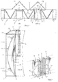
- the quick-closing valve basically consists of a frame 1 with at least one through-flow slot 2, which is provided with an adjustable closing element 3, which can be brought from an air pressure-dependent adjustment drive 4 to the through-flow slot 2 in the closed and open positions. It is essential for such a quick-release valve that the edges 5 which laterally delimit the at least one through-flow slot 2 (several are shown) and which form the valve seats for the respective spring leaf 3 'are convexly curved with respect to the inflow direction and the closing element 3 behind these edges 5 is designed and arranged in the form of a likewise convex but weakly curved spring leaf 3 ', the length L of which corresponds at least to the length of the convexly curved edges 5 of the throughflow slot 2 and is held at one end 6 on the frame 1 and with its other end region 7 on Frame 1 is guided.
- the end region 7 of the spring leaf 3 ' which is displaceably guided on the frame 1 is connected to the Adjustment drive 4 connected, in the exemplary embodiment shown in such a way that on the frame 1 in the region of the spring leaf 3 'projecting in the open position, an actuator 10 extending transversely to the latter is fixedly arranged with an end 11 which is in operative connection with the spring leaf 3' its other free end 11 is coupled to the actuator 4.
- an actuator 10 extending transversely to the latter is fixedly arranged with an end 11 which is in operative connection with the spring leaf 3' its other free end 11 is coupled to the actuator 4.
- this configuration results in a spatially advantageous assignment of the adjustment drive (s) 4, as shown, vertically and in the flow shadow behind the spring leaf (s) 3 '.
- the convexly curved edges 5 are designed as edges of webs 8 arranged in the frame, which form flank legs 8 ′ of M-profiles 9 arranged in the frame. Two adjacent M-profiles 9 thus each delimit a throughflow slot 2 with their flank legs 8 '. As can be seen from the flow arrows in particular in FIG. 1, this results in favorable and largely swirl-free conditions for the outflowing air when the valve is open.
- 2 flow guide elements 13 are arranged in front of the throughflow slots, which are also fastened to the frame 1 in a suitable manner. These flow guide elements 13 can also be designed as snow-repellent air grilles.
- one end 6 of the spring leaf 3 ' is firmly bound in the frame 1 by, for example, folding.
- the weakly convex shape of the spring leaves 3 ' is important insofar as the direction of adjustment against the edges 5 is thus ensured under load.
- flat spring leaves would also be possible, but additional measures would have to be taken to ensure that such spring leaves can only bend towards the edges 5 and bear against them when loaded.
Landscapes
- Engineering & Computer Science (AREA)
- Mechanical Engineering (AREA)
- Chemical & Material Sciences (AREA)
- Combustion & Propulsion (AREA)
- General Engineering & Computer Science (AREA)
- Air-Flow Control Members (AREA)
- Safety Valves (AREA)
- Multiple-Way Valves (AREA)
- Fluid-Pressure Circuits (AREA)
- Vehicle Body Suspensions (AREA)
- Valves And Accessory Devices For Braking Systems (AREA)
Abstract
Description
- Die Erfindung betrifft ein Schnellschlußventil zur Anordnung an Ansaug- und Ausblasöffnungen von Belüftungsanlagen, insbesondere schnellfahrender Eisenbahnfahrzeuge, bestehend aus einem Rahmen mit mindestens einem Durchströmschlitz, der mit einem verstellbaren Schließelement versehen ist, das von einem luftdruckabhängig gesteuerten Verstellantrieb zum Durchströmschlitz in Schließ- und Öffnungsstellung bringbar ist.
- In schnellfahrenden Eisenbahnfahrzeugen treten bei Tunnelfahrten oder auch bei Zugbegegnungen durch die relativ großen Ansaug- und Ausblasöffnungen der Belüftungsanlagen Druckwellen ins Wageninnere, die für die Fahrgäste unangenehm sind und durch schnelles Schließen dieser Öffnungen bei Auftreten einer Druckwelle auf Werte herabgesetzt werden können, die nicht mehr unangenehm empfunden werden.
- Druckwellenventile der eingangs genannten und bekannten Art bspw. nach der DE-A-36 18 292 werden in der Form von Schlitzschiebern ausgeführt. Sie bestehen aus zwei äußeren Platten mit gegenüberliegenden Öffnungen und einer beweglichen mittleren Platte, ebenfalls mit Schlitzen, die durch mechanische Bewegung so verschoben wird, daß die Schlitze nicht mehr übereinstimmen.
- Durch die mechanische Bewegung entsteht an den Platten Reibung und Verschleiß. Außerdem muß der Verstellantrieb die mittlere Platte zurückziehen, und/oder es muß zusätzlich zur Platte eine Rückstellfeder vorgesehen werden.
- Für Luftaustrittsöffnungen von Schutzräumen ist nach der CH-A-427 514 eine Schnellschlußvorrichtung bekannt, mit der äußere Druck- oder Sogwellen abgefangen werden. Der mindestens eine Luftdurchlaßschlitz wird dabei von zwei Rahmen begrenzt, die in bezug auf ein zwischen diesen angeordnetes streifenförmiges Schließteil konkave Sitzflächen für das Schließteil aufweisen, das sich bei einer Druckwelle an das eine Sitzflächenpaar und bei einer Sogwelle an das andere Sitzflächenpaar anlegt und dabei den Luftdurchlaßschlitz schließt. Hierbei handelt es sich also gewissermaßen um ein Flatterventil, das schon aus diesem Grunde für den vorliegenden Zweck nicht geeignet ist, ganz abgesehen davon, daß dieses nicht gezielt bzw. gesteuert geöffnet und geschlossen werden kann. Gleiches gilt bei in etwa entsprechender Ausbildung für eine selbsttätige sogenannte Luftstoßsicherung nach der DE-Z.: Die Kälte und Klimatechnik 11/1986, S. 558 und 559.
- Der Erfindung liegt, ausgehend von einem Schnellschlußventil der gattungsgemäßen Art die Aufgabe zugrunde, ein solches Ventil dahingehend auszubilden und zu verbessern, daß die Öffnungs- und Schließbewegungen des Schließelementes praktisch ohne Reibung erfolgen können und daß sich das Schließelement nach Wegfall der Schließbelastung selbsttätig in seine Öffnungsstellung zurückstellt.
- Diese Aufgabe ist mit einem Schnellschlußventil nach der Erfindung dadurch gelöst, daß die den mindestens einen Durchströmschlitz seitlich begrenzenden Ränder in bezug auf die Anströmrichtung konvex gewölbt sind und hinter diesen Rändern das Schließelement in Form eines ebenfalls konvexen aber schwächer gewölbten Federblattes ausgebildet und angeordnet ist, das in seiner Länge mindestens der Länge der konvex gewölbten Ränder des Durchströmschlitzes entspricht und mit einem Ende am Rahmen gehalten und mit seinem anderen Endbereich am Rahmen verschieblich geführt ist.
- Da das Federblatt bei gegebenem Betätigungsimpuls lediglich gegen die konvex gewölbten Ränder des Durchströmschlitzes angelegt wird und aus der angelegten Schließstellung bei Aufhebung der Schließbelastung in die Öffnungsstellung zurückschnellt und dabei nur mit seinen Enden mit dem Rahmen in Verbindung steht, ist die Reibung im Vergleich zu Schieberventilen ganz wesentlich reduziert.
- Der Steuerimpuls für die Betätigung des Stellantriebes, der wie bisher ein kleiner Pneumatikzylinder sein kann oder ein elektromagnetischer Antrieb, wird ebenfalls wie bisher durch einen Druckwellensensor geliefert, der bspw. ein sogenannter Druckwellenvetilator sein kann und der, da bekannt, hier keiner näheren Erläuterung bedarf.
- Vorteilhafte weitere Ausgestaltungen bestehen in Folgendem:
Der verschieblich am Rahmen geführte Endbereich des Federblattes ist mit dem Verstellantrieb verbunden. Dies ist günstiger als den Verstellantrieb etwa mittig am Federblatt anzukoppeln, was grundsätzlich auch möglich wäre. - Die konvex gewölbten Ränder sind als Ränder von im Rahmen angeordneten Stegen ausgebildet, wobei die Stege Flankenschenkel von im Rahmen angeordneten M-Profilen bilden. Dies ist nicht nur abströmgünstig, sondern nimmt auch Rücksicht darauf, daß derartige Schnellschlußventile in der Regel nebeneinander mehrere Durchströmschlitze aufweisen.
- Ferner ist am Rahmen im Bereich des in Öffnungsstellung oben stehenden Federblattes ein sich zu diesem quer erstreckenden Stellelement mit einem Ende fest angeordnet, das mit dem Federblatt in Wirkverbindung und mit seinem anderen freien Ende mit dem Stellantrieb gekoppelt ist. Dies sorgt nicht nur für eine günstige Anlenkung des Stellantriebes zum Federblatt, sondern mit diesem noch näher zu erläuternden Stellelement können alle zu einer ganzen Durchströmschlitzreihe gehörenden Federblätter erfaßt werden, was bedeutet, daß für alle Federblätter nur ein Stellantrieb erforderlich ist.
- Das erfindungsgemäße Schnellschlußventil wird nachfolgend anhand der zeichnerischen Darstellung eines Ausführungsbeispieles näher erläutert, das nebeneinander mehrere Durchströmschlitze aufweist.
- Es zeigt schematisch
- Fig. 1
- einen Schnitt durch das Schnellschlußventil längs Linie I-I in Fig. 2;
- Fig. 2
- einen Schnitt durch das Schnellschlußventil längs Linie II-II in Fig. 1 und
- Fig. 3
- eine vereinfachte und perspektivische Darstellung des Schnellschlußventiles.
- Das Schnellschlußventil besteht grundsätzlich aus einem Rahmen 1 mit mindestens einem Durchströmschlitz 2, der mit einem verstellbaren Schließelement 3 versehen ist, das von einem luftdruckabhängig gesteuerten Verstellantrieb 4 zum Durchströmschlitz 2 in Schließ- und Öffnungsstellung bringbar ist. Wesentlich für ein solches Schnellverschlußventil ist nun, daß die den mindestens einen Durchströmschlitz 2 (dargestellt sind mehrere) seitlich begrenzenden und die Ventilsitze für das jeweilige Federblatt 3' bildenden Ränder 5 in bezug auf die Anströmrichtung konvex gewölbt sind und hinter diesen Rändern 5 das Schließelement 3 in Form eines ebenfalls konvexen, aber schwächer gewölbten Federblattes 3' ausgebildet und angeordnet ist, das in seiner Länge L mindestens der Länge der konvex gewölbten Ränder 5 des Durchströmschlitzes 2 entspricht und mit einem Ende 6 am Rahmen 1 gehalten und mit seinem anderen Endbereich 7 am Rahmen 1 verschieblich geführt ist.
- Wie aus Fig. 2 ersichtlich, ist der verschieblich am Rahmen 1 geführte Endbereich 7 des Federblattes 3' mit dem Verstellantrieb 4 verbunden, und zwar beim dargestellten Ausführungsbeispiel derart, daß am Rahmen 1 im Bereich des in Öffnungsstellung überstehenden Federblattes 3' ein sich zu diesem quer erstreckenden Stellelement 10 mit einem Ende 11 fest angeordnet ist, das mit dem Federblatt 3' in Wirkverbindung und mit seinem anderen freien Ende 11 mit dem Stellantrieb 4 gekoppelt ist. Abgesehen davon, daß eine solche Ausbildung für jedes vorhandene Federblatt 3' vorgesehen werden könnte, ist es aber auch möglich, mit dem Stellelement 10 alle Federblätter 3' zu erfassen und am Stellelement 10, wie in Fig. 2 dargestellt, nur einen Verstellantrieb 4 anzulenken. Im übrigen ergibt sich durch diese Ausgestaltung eine auch räumlich vorteilhafte Zuordnung des bzw. der Verstellantriebe 4 wie dargestellt vertikal und im Strömungsschatten hinter dem bzw. den Federblättern 3'.
- Wie insbesondere aus Fig. 3 deutlich wird, sind beim Ausführungsbeispiel die konvex gewölbten Ränder 5 als Ränder von im Rahmen angeordneten Stegen 8 ausgebildet, die Flankenschenkel 8' von im Rahmen angeordneten M-Profilen 9 bilden. Zwei benachbarte M-Profile 9 begrenzen also mit ihren Flankenschenkeln 8' jeweils einen Durchströmschlitz 2. Wie die Strömungspfeile insbesondere in Fig. 1 erkennen lassen, ergeben sich dadurch günstige und weitgehend verwirbelungsfreie Verhältnisse für die abströmende Luft bei geöffnetem Ventil. In Anströmrichtung sind, wie in Fig. 1 dargestellt, vor den Durchströmschlitzen 2 Strömungsleitelemente 13 angeordnet, die in geeigneter Weise ebenfalls am Rahmen 1 befestigt werden. Diese Strömungsleitelemente 13 können dabei auch als schneeabweisende Luftgitter ausgebildet sein.
- Wie aus Fig. 2 ersichtlich, ist das eine Ende 6 des Federblattes 3' durch bspw. Einfalzung fest im Rahmen 1 eingebunden. Für die Führung des überstehenden Endbereiches 7 sind insbesondere bei einer Kopplung mit dem Stellelement 10 noch nicht einmal besondere Ausgestaltungen des Rahmens 1 in diesem Bereich erforderlich, da sich dort die Federblätter 3' einfach anlegen. Die schwach konvexe Formgebung der Federblätter 3' hat insofern Bedeutung, als damit bei Belastung die Verstellrichtung gegen die Ränder 5 sichergestellt ist. Insofern wären auch ebene Federblätter möglich, dabei müßte aber durch Zusatzmaßnahmen dafür gesorgt werden, daß sich solche Federblätter bei Belastung nur zu den Rändern 5 hin ausbiegen und an diese anlegen können.
Claims (6)
- Schnellschlußventil zur Anordnung an Ansaug- und Ausblasöffnungen von Belüftungsanlagen, insbesondere schnellfahrender Eisenbahnfahrzeuge, bestehend aus einem Rahmen (1) mit mindestens einem Durchströmschlitz (2), der mit einem verstellbaren Schließelement (3) versehen ist, das von einem luftdruckabhängig gesteuerten Verstellantrieb (4) zum Durchströmschlitz (2) in Schließ- und Öffnungsstellung bringbar ist,
dadurch gekennzeichnet,
daß die den mindestens einen Durchströmschlitz (2) seitlich begrenzenden Ränder (5) in bezug auf die Anströmrichtung konvex gewölbt sind und hinter diesen Rändern (5) das Schließelement (3) in Form eines ebenfalls konvexen, aber schwächer gewölbten Federblattes (3') ausgebildet und angeordnet ist, das in seiner Länge (L) mindestens der Länge der konvex gewölbten Ränder (5) des Durchströmschlitzes (2) entspricht und mit einem Ende (6) am Rahmen (1) gehalten und mit seinem anderen Endbereich (7) am Rahmen (1) verschieblich geführt ist. - Ventil nach Anspruch 1,
dadurch gekennzeichnet,
daß der verschieblich am Rahmen (1) geführte Endbereich (7) des Federblattes (3') mit dem Verstellantrieb (4) verbunden ist. - Ventil nach Anspruch 1 oder 2,
dadurch gekennzeichnet,
daß die konvex gewölbten Ränder (5) Ränder von im Rahmen (1) angeordneten Stegen (8) sind. - Ventil nach Anspruch 3,
dadurch gekennzeichnet,
daß die Stege (8) als Flankenschenkel (8') von im Rahmen (1) angeordneten M-Profilen (9) ausgebildet sind. - Ventil nach einem der Ansprüche 1 bis 4,
dadurch gekennzeichnet,
daß am Rahmen (1) im Bereich des in Öffnungsstellung überstehenden Federblattes (3') ein sich zu diesem quer erstreckenden Stellelement (10) mit einem Ende (11) fest angeordnet ist, das mit dem Federblatt (3') in Wirkverbindung und mit seinem anderen freien Ende (11) mit dem Stellantrieb (4) gekoppelt ist. - Ventil nach einem der Ansprüche 1 bis 5,
dadurch gekennzeichnet,
daß in Distanz und in Anströmrichtung vor dem mindestens einen Durchströmschlitz (2) ein Strömungsleitelement (13) angeordnet ist.
Applications Claiming Priority (2)
| Application Number | Priority Date | Filing Date | Title |
|---|---|---|---|
| DE4238942 | 1992-11-19 | ||
| DE4238942A DE4238942C1 (de) | 1992-11-19 | 1992-11-19 | Schnellschlußventil zur Anordnung an Ansaug- und Ausblasöffnungen von Belüftungsanlagen |
Publications (2)
| Publication Number | Publication Date |
|---|---|
| EP0598210A1 true EP0598210A1 (de) | 1994-05-25 |
| EP0598210B1 EP0598210B1 (de) | 1995-09-27 |
Family
ID=6473205
Family Applications (1)
| Application Number | Title | Priority Date | Filing Date |
|---|---|---|---|
| EP93116114A Expired - Lifetime EP0598210B1 (de) | 1992-11-19 | 1993-10-06 | Schnellschlussventil zur Anordnung an Ansaug- und Ausblasöffnungen von Belüftungsanlagen |
Country Status (7)
| Country | Link |
|---|---|
| US (1) | US5351933A (de) |
| EP (1) | EP0598210B1 (de) |
| KR (1) | KR100286852B1 (de) |
| CN (1) | CN1030495C (de) |
| AT (1) | ATE128423T1 (de) |
| DE (1) | DE4238942C1 (de) |
| ES (1) | ES2078786T3 (de) |
Cited By (1)
| Publication number | Priority date | Publication date | Assignee | Title |
|---|---|---|---|---|
| US11119956B2 (en) | 2004-03-02 | 2021-09-14 | Xilinx, Inc. | Dual-driver interface |
Families Citing this family (5)
| Publication number | Priority date | Publication date | Assignee | Title |
|---|---|---|---|---|
| DE4404032C1 (de) * | 1994-02-09 | 1995-03-23 | Hagenuk Fahrzeugklima Gmbh | Druckwellenventil |
| GB0408868D0 (en) | 2004-04-21 | 2004-05-26 | Level 5 Networks Ltd | Checking data integrity |
| GB0505300D0 (en) | 2005-03-15 | 2005-04-20 | Level 5 Networks Ltd | Transmitting data |
| WO2006095184A2 (en) | 2005-03-10 | 2006-09-14 | Level 5 Networks Incorporated | Data processing system |
| DE202014104358U1 (de) * | 2014-09-15 | 2014-12-12 | Faiveley Transport Leipzig Gmbh & Co. Kg | Vorrichtung für eine kombinierte Druckschutz- und Luftmengenregelung im Innenraum von Schienenfahrzeugen |
Citations (4)
| Publication number | Priority date | Publication date | Assignee | Title |
|---|---|---|---|---|
| US3139108A (en) * | 1962-09-24 | 1964-06-30 | Klingman Sanford | Pressure operated valve means |
| CH449433A (de) * | 1966-05-16 | 1967-12-31 | Luwa Ag | Schnellschlussvorrichtung an Luftdurchlassöffnungen für Schutzräume |
| EP0315108A2 (de) * | 1987-11-02 | 1989-05-10 | Hitachi, Ltd. | Lüftungsausrüstung für rollendes Material |
| EP0336909A2 (de) * | 1988-04-05 | 1989-10-11 | ITALARMS S.r.l. | Ventil zum Schützen der Ventilationsöffnungen geschlossener Räume gegen Explosionswellen |
Family Cites Families (7)
| Publication number | Priority date | Publication date | Assignee | Title |
|---|---|---|---|---|
| US3057373A (en) * | 1959-10-19 | 1962-10-09 | Parker Hannifin Corp | Flow limiting valve |
| CH427514A (de) * | 1963-04-18 | 1966-12-31 | Luwa Ag | Schnellschlussvorrichtung an Luftdurchlassöffnungen für Schutzräume |
| US4316408A (en) * | 1980-05-19 | 1982-02-23 | Carrier Corporation | Damper assembly for use with an air conditioning system |
| CA1266199A (en) * | 1985-01-28 | 1990-02-27 | Waldemar H. Greiner | Damper construction |
| DE3618292C3 (de) * | 1986-05-30 | 1995-12-07 | Rainer Herma | Motorisch betätigbares Druckventil für Kabinen von Eisenbahnwagen |
| US5106052A (en) * | 1991-05-09 | 1992-04-21 | Dipti Datta | Air damper apparatus |
| US5139048A (en) * | 1991-10-11 | 1992-08-18 | Armstrong George W | Direct powered gate valve |
-
1992
- 1992-11-19 DE DE4238942A patent/DE4238942C1/de not_active Expired - Fee Related
-
1993
- 1993-10-06 EP EP93116114A patent/EP0598210B1/de not_active Expired - Lifetime
- 1993-10-06 AT AT93116114T patent/ATE128423T1/de not_active IP Right Cessation
- 1993-10-06 ES ES93116114T patent/ES2078786T3/es not_active Expired - Lifetime
- 1993-11-10 US US08/150,470 patent/US5351933A/en not_active Expired - Fee Related
- 1993-11-18 KR KR1019930024598A patent/KR100286852B1/ko not_active IP Right Cessation
- 1993-11-18 CN CN93114788A patent/CN1030495C/zh not_active Expired - Fee Related
Patent Citations (4)
| Publication number | Priority date | Publication date | Assignee | Title |
|---|---|---|---|---|
| US3139108A (en) * | 1962-09-24 | 1964-06-30 | Klingman Sanford | Pressure operated valve means |
| CH449433A (de) * | 1966-05-16 | 1967-12-31 | Luwa Ag | Schnellschlussvorrichtung an Luftdurchlassöffnungen für Schutzräume |
| EP0315108A2 (de) * | 1987-11-02 | 1989-05-10 | Hitachi, Ltd. | Lüftungsausrüstung für rollendes Material |
| EP0336909A2 (de) * | 1988-04-05 | 1989-10-11 | ITALARMS S.r.l. | Ventil zum Schützen der Ventilationsöffnungen geschlossener Räume gegen Explosionswellen |
Cited By (2)
| Publication number | Priority date | Publication date | Assignee | Title |
|---|---|---|---|---|
| US11119956B2 (en) | 2004-03-02 | 2021-09-14 | Xilinx, Inc. | Dual-driver interface |
| US11182317B2 (en) | 2004-03-02 | 2021-11-23 | Xilinx, Inc. | Dual-driver interface |
Also Published As
| Publication number | Publication date |
|---|---|
| ES2078786T3 (es) | 1995-12-16 |
| KR100286852B1 (ko) | 2001-04-16 |
| CN1030495C (zh) | 1995-12-13 |
| ATE128423T1 (de) | 1995-10-15 |
| EP0598210B1 (de) | 1995-09-27 |
| CN1088882A (zh) | 1994-07-06 |
| DE4238942C1 (de) | 1994-01-05 |
| US5351933A (en) | 1994-10-04 |
| KR940011273A (ko) | 1994-06-20 |
Similar Documents
| Publication | Publication Date | Title |
|---|---|---|
| DE102010035805B4 (de) | Druckentlastungsventil für eine Fahrzeugkarosserie | |
| DE2153743C3 (de) | Luftdüse für eine Belüftungsanlage | |
| DE102010039620A1 (de) | Kühlergrill für ein Kraftfahrzeug | |
| DE102004048038A1 (de) | Verschließbare Kraftfahrzeug-Kühlergrillanordnung | |
| DE102009007037A1 (de) | Ausströmdüse einer Belüftungsvorrichtung oder Klimaanlage für Fahrzeuge | |
| DE102019118243A1 (de) | Luftausströmer | |
| DE102006053883A1 (de) | Kühlerbaugruppe für ein Fahrzeug | |
| DE102011055394A1 (de) | Luftklappenanordnung und Verfahren zur Steuerung eines Kühlluftstromes in einen Motorraum eines Fahrzeuges | |
| DE102016007369A1 (de) | Kühlerjalousie für ein Kraftfahrzeug | |
| EP2699476B1 (de) | Ventil zur steuerung des innendrucks in einer kabine eines luftfahrzeugs | |
| EP2356021A2 (de) | Flügel mit einer stellklappe und einer spaltabdeckungs-vorrichtung und verstellmechanismus für eine spaltabdeckungs-vorrichtung | |
| DE2412098C2 (de) | Strömungsverteiler für eine Fahrzeug-Belüftungs-, Heizungs- oder -Klimaanlage | |
| EP0598210B1 (de) | Schnellschlussventil zur Anordnung an Ansaug- und Ausblasöffnungen von Belüftungsanlagen | |
| DE2653106C2 (de) | Klappenhalter | |
| DE102018211373A1 (de) | Kompakter Luftausströmer zum Führen eines Luftstroms | |
| DE69406326T2 (de) | Vorhang mit Strömungsregelung | |
| DE102015202815A1 (de) | Schienenfahrzeug mit Kühlanlage | |
| DE2704136C2 (de) | Steuereinrichtung für ein Raumluft-Temperiergerät | |
| DE4436942C1 (de) | Aus zwei schwenkbaren Flügeln bestehende Klappenanordnung | |
| DE19632147A1 (de) | Heiz- oder Klimaanlage | |
| DE102020108169A1 (de) | Luftausströmer | |
| DE102022129306A1 (de) | Luftausströmer | |
| DE2557582C3 (de) | Überdruckklappe für Ventilator | |
| DE202014104358U1 (de) | Vorrichtung für eine kombinierte Druckschutz- und Luftmengenregelung im Innenraum von Schienenfahrzeugen | |
| DE19915544A1 (de) | Windabweiseranordnung für eine Dachöffnung eines Fahrzeugs |
Legal Events
| Date | Code | Title | Description |
|---|---|---|---|
| PUAI | Public reference made under article 153(3) epc to a published international application that has entered the european phase |
Free format text: ORIGINAL CODE: 0009012 |
|
| AK | Designated contracting states |
Kind code of ref document: A1 Designated state(s): AT ES FR GB IT |
|
| 17P | Request for examination filed |
Effective date: 19940408 |
|
| 17Q | First examination report despatched |
Effective date: 19950208 |
|
| GRAA | (expected) grant |
Free format text: ORIGINAL CODE: 0009210 |
|
| AK | Designated contracting states |
Kind code of ref document: B1 Designated state(s): AT ES FR GB IT |
|
| REF | Corresponds to: |
Ref document number: 128423 Country of ref document: AT Date of ref document: 19951015 Kind code of ref document: T |
|
| ET | Fr: translation filed | ||
| REG | Reference to a national code |
Ref country code: ES Ref legal event code: FG2A Ref document number: 2078786 Country of ref document: ES Kind code of ref document: T3 |
|
| ITF | It: translation for a ep patent filed | ||
| GBT | Gb: translation of ep patent filed (gb section 77(6)(a)/1977) |
Effective date: 19960106 |
|
| PLBE | No opposition filed within time limit |
Free format text: ORIGINAL CODE: 0009261 |
|
| STAA | Information on the status of an ep patent application or granted ep patent |
Free format text: STATUS: NO OPPOSITION FILED WITHIN TIME LIMIT |
|
| 26N | No opposition filed | ||
| PGFP | Annual fee paid to national office [announced via postgrant information from national office to epo] |
Ref country code: ES Payment date: 20000922 Year of fee payment: 8 |
|
| PGFP | Annual fee paid to national office [announced via postgrant information from national office to epo] |
Ref country code: AT Payment date: 20001031 Year of fee payment: 8 |
|
| PG25 | Lapsed in a contracting state [announced via postgrant information from national office to epo] |
Ref country code: AT Free format text: LAPSE BECAUSE OF NON-PAYMENT OF DUE FEES Effective date: 20011006 |
|
| PG25 | Lapsed in a contracting state [announced via postgrant information from national office to epo] |
Ref country code: ES Free format text: LAPSE BECAUSE OF NON-PAYMENT OF DUE FEES Effective date: 20011007 |
|
| REG | Reference to a national code |
Ref country code: GB Ref legal event code: IF02 |
|
| REG | Reference to a national code |
Ref country code: GB Ref legal event code: 732E |
|
| REG | Reference to a national code |
Ref country code: FR Ref legal event code: TP |
|
| REG | Reference to a national code |
Ref country code: ES Ref legal event code: FD2A Effective date: 20021113 |
|
| PG25 | Lapsed in a contracting state [announced via postgrant information from national office to epo] |
Ref country code: IT Free format text: LAPSE BECAUSE OF NON-PAYMENT OF DUE FEES;WARNING: LAPSES OF ITALIAN PATENTS WITH EFFECTIVE DATE BEFORE 2007 MAY HAVE OCCURRED AT ANY TIME BEFORE 2007. THE CORRECT EFFECTIVE DATE MAY BE DIFFERENT FROM THE ONE RECORDED. Effective date: 20051006 |
|
| PGFP | Annual fee paid to national office [announced via postgrant information from national office to epo] |
Ref country code: GB Payment date: 20060925 Year of fee payment: 14 |
|
| GBPC | Gb: european patent ceased through non-payment of renewal fee |
Effective date: 20071006 |
|
| REG | Reference to a national code |
Ref country code: FR Ref legal event code: ST Effective date: 20080630 |
|
| PGFP | Annual fee paid to national office [announced via postgrant information from national office to epo] |
Ref country code: FR Payment date: 20061013 Year of fee payment: 14 |
|
| PG25 | Lapsed in a contracting state [announced via postgrant information from national office to epo] |
Ref country code: GB Free format text: LAPSE BECAUSE OF NON-PAYMENT OF DUE FEES Effective date: 20071006 |
|
| PG25 | Lapsed in a contracting state [announced via postgrant information from national office to epo] |
Ref country code: FR Free format text: LAPSE BECAUSE OF NON-PAYMENT OF DUE FEES Effective date: 20071031 |