EP0597629A1 - Display - Google Patents
Display Download PDFInfo
- Publication number
- EP0597629A1 EP0597629A1 EP93308821A EP93308821A EP0597629A1 EP 0597629 A1 EP0597629 A1 EP 0597629A1 EP 93308821 A EP93308821 A EP 93308821A EP 93308821 A EP93308821 A EP 93308821A EP 0597629 A1 EP0597629 A1 EP 0597629A1
- Authority
- EP
- European Patent Office
- Prior art keywords
- display
- lenses
- array
- light source
- light
- Prior art date
- Legal status (The legal status is an assumption and is not a legal conclusion. Google has not performed a legal analysis and makes no representation as to the accuracy of the status listed.)
- Granted
Links
Images


Classifications
-
- G—PHYSICS
- G09—EDUCATION; CRYPTOGRAPHY; DISPLAY; ADVERTISING; SEALS
- G09F—DISPLAYING; ADVERTISING; SIGNS; LABELS OR NAME-PLATES; SEALS
- G09F19/00—Advertising or display means not otherwise provided for
- G09F19/12—Advertising or display means not otherwise provided for using special optical effects
- G09F19/14—Advertising or display means not otherwise provided for using special optical effects displaying different signs depending upon the view-point of the observer
-
- G—PHYSICS
- G02—OPTICS
- G02B—OPTICAL ELEMENTS, SYSTEMS OR APPARATUS
- G02B30/00—Optical systems or apparatus for producing three-dimensional [3D] effects, e.g. stereoscopic images
- G02B30/20—Optical systems or apparatus for producing three-dimensional [3D] effects, e.g. stereoscopic images by providing first and second parallax images to an observer's left and right eyes
- G02B30/26—Optical systems or apparatus for producing three-dimensional [3D] effects, e.g. stereoscopic images by providing first and second parallax images to an observer's left and right eyes of the autostereoscopic type
- G02B30/27—Optical systems or apparatus for producing three-dimensional [3D] effects, e.g. stereoscopic images by providing first and second parallax images to an observer's left and right eyes of the autostereoscopic type involving lenticular arrays
-
- G—PHYSICS
- G09—EDUCATION; CRYPTOGRAPHY; DISPLAY; ADVERTISING; SEALS
- G09F—DISPLAYING; ADVERTISING; SIGNS; LABELS OR NAME-PLATES; SEALS
- G09F19/00—Advertising or display means not otherwise provided for
- G09F19/12—Advertising or display means not otherwise provided for using special optical effects
-
- H—ELECTRICITY
- H04—ELECTRIC COMMUNICATION TECHNIQUE
- H04N—PICTORIAL COMMUNICATION, e.g. TELEVISION
- H04N13/00—Stereoscopic video systems; Multi-view video systems; Details thereof
- H04N13/30—Image reproducers
- H04N13/302—Image reproducers for viewing without the aid of special glasses, i.e. using autostereoscopic displays
- H04N13/32—Image reproducers for viewing without the aid of special glasses, i.e. using autostereoscopic displays using arrays of controllable light sources; using moving apertures or moving light sources
-
- H—ELECTRICITY
- H04—ELECTRIC COMMUNICATION TECHNIQUE
- H04N—PICTORIAL COMMUNICATION, e.g. TELEVISION
- H04N13/00—Stereoscopic video systems; Multi-view video systems; Details thereof
- H04N13/30—Image reproducers
- H04N13/302—Image reproducers for viewing without the aid of special glasses, i.e. using autostereoscopic displays
- H04N13/305—Image reproducers for viewing without the aid of special glasses, i.e. using autostereoscopic displays using lenticular lenses, e.g. arrangements of cylindrical lenses
-
- H—ELECTRICITY
- H04—ELECTRIC COMMUNICATION TECHNIQUE
- H04N—PICTORIAL COMMUNICATION, e.g. TELEVISION
- H04N13/00—Stereoscopic video systems; Multi-view video systems; Details thereof
- H04N13/30—Image reproducers
- H04N13/302—Image reproducers for viewing without the aid of special glasses, i.e. using autostereoscopic displays
- H04N13/31—Image reproducers for viewing without the aid of special glasses, i.e. using autostereoscopic displays using parallax barriers
Definitions
- the present invention relates to a display.
- a display may be used as a non-holographic three-dimensional (3D) display which is capable of forming a 3D image of opaque moving objects.
- a known type of 3D display creates an illusion of a 3D image to a human observer by displaying a plurality of two-dimensional (2D) images in sequence.
- Each of the 2D images comprises a view of an object from a particular direction and is replayed in that direction.
- the perceived quality of 3D images provided by such techniques improves as the size of the display is increased.
- GB-A-2 206 763 discloses a stereoscopic display apparatus in which light, from a light source positioned in the focal plane of a converging lens, is converted into parallel rays of light before being passed through a spatial light modulator.
- US 5 062 689 discloses a projection display in which light is modulated by a spatial light modulator and then imaged on a screen.
- US 3 858 001 discloses a stereoscopic display apparatus in which first and second images are polarised in first and second directions, respectively. The viewer wears spectacles containing analysers so that each eye receives only a respective image.
- GB-A-1 273 062 discloses a stereoscopic display apparatus in which an image on a CRT is displayed through an array of lenses or pin holes.
- British Patent Application No.9210399.3 discloses a 3D display in which temporal and spatial multiplexing are used to provide an autostereoscopic 3D image. By combining temporal and spatial multiplexing, an increased number of 2D views can be provided. However, the number of 2D views is limited by the maximum update rate and resolution of presently available spatial light modulators (SLM).
- SLM spatial light modulators
- each eye of an observer located at a given position will not see the same 2D view across the whole of the screen. Instead, the eye will see juxtaposed vertical slices of two or more different views on the screen with each slice having a width which is dependent on the position of the observer with respect to the display and on the display optical geometry. Each eye sees a different set of view slices which would give the appearance of a 3D image. However, the view slices can cause problems in the perception of a 3D image.
- the display size is limited by the maximum update rates and resolutions of presently available SLMs.
- a display for producing an autostereoscopic image comprising at least one light source for producing a divergent beam of light, and a spatial light modulator comprising a plurality of light modulating cells for modulating light passing therethrough from the at least one light source in accordance with image data, characterised by: a first array of lenses or apertures arranged to receive the divergent light beam from the or each light source, each of the lenses or apertures being arranged to produce an image of the or each light source at a common image plane such that each image is laterally displaced by a respective predetermined amount from an optical axis of the corresponding lens or aperture and the respective predetermined amounts vary progressively across the common image plane; and a second array of lenses or apertures having a common object plane which coincides with the common image plane.
- the apertures may be elongate.
- the first array of lenses or apertures is located between the at least one light source and the spatial light modulator.
- the spatial light modulator may be located between the at least one light source and the first array of lenses or apertures.
- the lenses of the first and second arrays are preferably converging lenses.
- the first and second arrays may comprise lenticular screens, for instance in the form of a plurality of parallel elongate lenticules having cylindrical convergent properties.
- the at least one light source may comprise a linear array of light sources extending perpendicularly to the lenticules. Such an arrangement may be used to provide horizontal parallax. Where both horizontal and vertical parallax is required, the first and second arrays may comprise 2D arrays of lenses, for instance in the form of microlens arrays.
- the lenses may be of the spherical convergent type and the at least one light source may comprise a two dimensional array of light sources. In either case, the light sources may be illuminated one at a time sequentially by suitable control means.
- the or each light source may be contiguous with the or each adjacent light source.
- the pitch of the lenses or apertures of the first array may be substantially equal to the pitch of the cells of the spatial light modulator. This pitch may be less than the pitch of the lenses or apertures of the second array, which may for instance be an integer multiple of the pitch of the lenses or apertures of the first array and the pitch of the cells of the modulator.
- a diffuser may be located between the modulator and the second array.
- the diffuser is preferably located at or adjacent a common focal plane of the lenses of the second array, and at an image plane of the or each light source imaged by the lenses of the first array.
- a field lens may be interposed between the first and second arrays.
- An opaque barrier may be disposed between the modulator or diffuser and the second array for blocking transverse light paths.
- a display which is capable of being used as a large 3D display with each eye of an observer at a given position observing a single 2D view across the whole of the display.
- the eyes of the observer see different 2D views, thus giving the appearance of a 3D image.
- Such a display has many possible uses, for instance in television, computer aided design, medical imaging, video games, simultaneous 3D and 2D presentation, and virtual reality displays.
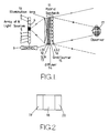
- the light sources 1 to 8 are contiguous so as to form a continuous strip.
- the light sources are connected to a control circuit 9, which causes the light sources to be illuminated one at a time repetitively in order, Figure 1 indicating that the light source 5 is illuminated.
- the linear array of light sources 1 to 8 is disposed in the focal plane of an illumination or collimating system 10, which is shown as a plano-convex lens having a cylindrical convex surface.
- the system 10 produces collimated light from each point of each of the light sources 1 to 8. Because the light sources have finite dimensions, the light output of the collimating system has a spread of angles.
- the hybrid sandwich comprises a lenticular screen (LS1) 12 formed by a plurality of contiguous cylindrical converging lens elements or lenticules having a horizontal pitch p.
- the screen 12 is followed by a SLM 13 in the form of a 2D liquid crystal device which is connected to the control circuit 9.
- the SLM 13 comprises a 2D array of picture elements whose light transmission properties (and colour transmission properties for a colour display) are controlled by the control circuit 9.
- the SLM is followed by a diffuser 14 which is separated by a grid or barrier 15 for blocking lateral light paths from a further lenticular screen (LS2) 16.
- the screen 16 is similar to the screen 12 but has a horizontal pitch equal to Mp, where M is an integer greater than 1.
- the light rays from the illuminated light source 5 are collimated into parallel light rays by the system 10 and are focused by the screen 12 through the SLM 13 onto the diffuser 14.
- the picture elements of the SLM 13 are controlled by the control circuit so as to provide, for instance, two views of the image taken from different directions during image capture. The two views are interlaced such that alternate strip portions correspond to a respective one of the views.
- the picture elements of the SLM 13 control the amount (and colour for a colour display) of light passing through the SLM so that a 2D array of images of the light source 5 is formed on the diffuser 14 corresponding to the two interlaced views.
- Each of the lenticules of the screen 16 converts the images on the diffuser 14 into output ray bundles whose angles of emission from the hybrid sandwich 11 depend on the lateral locations of the images on the diffuser 14 with respect to the optical axes of the lenticules.
- the two views represented on the SLM 13 are therefore visible from different angles corresponding to the angles of the object from which the views were taken during image capture.
- the grid or barrier 15 prevents each lenticule of the screen 16 from imaging the light images formed on the diffuser 14 and associated with adjacent lenticules of the screen 16.
- the control circuit 9 deactivates the light source 5 and causes the SLM 13 to display the next pair of interlaced views.
- the next light source 4 is then activated and the screen 12 images the light through the SLM 13 onto regions of the diffuser 14 which are laterally displaced with respect to the images formed when the light source 5 is illuminated.
- the lenticular screen 16 provides output ray bundles directed at different angles corresponding to the directions of the view of the object during image capture.
- each of the light sources of the linear array has been illuminated in turn, with the views represented on the SLM corresponding to a single "frame" of the 3D image.
- the whole sequence is then repeated for new sets of views representing consecutive frames constituting consecutive 3D images, the rate of repetition being sufficiently large to provide a substantially flicker-free image.
- the number of views making up each 3D image is equal to MxN.
- Figure 1 shows a display capable of providing 16 views per image
- practical SLMs may have refresh rates limited to 100 Hz so that, in order to provide a flicker-free image, the array of light sources may comprise only two sources.
- practical SLMs may have resolution limits such that only two views at a time can be produced.
- the number of views per frame may be limited to four.
- each eye of the observer sees only one of the views across the whole display in the direction corresponding to that from which the 2D view was captured.
- the limited resolution and frame rate of the SLM 13 and the optical geometry of the display can result in the appearance illustrated in Figure 2.
- a middle region 18 of the display one eye of the observer sees part of a first view.
- edge regions 19 and 20 of the display the same eye of the observer sees parts of second and third different views.
- the view slices can cause problems in the perception of a 3D image.
- the display shown in Figure 3 differs from that shown in Figure 1 in that the collimating system 10 is omitted. Also, the array of light sources is shown as comprising only four such sources 1 to 4. Otherwise, the control circuit 9 and the hybrid sandwich 11 are substantially identical to the corresponding parts of the display of Figure 1.
- the control circuit 9 controls the light sources 1 to 4 and the SLM 13 as described with reference to Figure 1.
- the hybrid sandwich 11 receives a divergent beam of light from each of the light sources 1 to 4, so that the light sources are imaged by the lenticules of the screen 12 through the SLM 13 onto different positions on the diffuser 14 located at an image plane of the first array.
- each light source is illuminated, its image on the diffuser 14 is at the same position as in the display of Figure 1 for the lenticule of the screen 12 on whose optical axis the light source is located, i.e. it has a lateral displacement of zero.
- the light source image is laterally displaced progressively further towards the edge of the diffuser as the lateral distance of the lenticule from the above-mentioned optical axis increases.
- This offset is illustrated at 21 in Figure 4 with the light source 3 illuminated.
- the lateral displacement therefore varies progressively across the whole of the diffuser, changing sign when the normal from the illuminated light source to the diffuser is passed.
- the direction of light emerging from each lenticule of the screen 16 varies progressively across the display, so that each view of the interlaced pair of views is projected towards a single point instead of in a single direction as for the display of Figure 1.
- Figure 4 illustrates at 24 the points or regions towards which the two views produced when the light source 3 is illuminated are projected.
- the diffuser 14 may be replaced by a field lens.
- Such an arrangement provides a limited region from which an observer may perceive the 3D effect.
- a display for a display of size 0.5 m with an observer located 1 m from the front surface, a display providing four views permits the observer to maintain a 3D image within a region which extends approximately 200 mm laterally on either side of a normal to the centre of the display and 260 mm in front of and behind the observer position.
- An SLM frame rate of 100 Hz permits a non-flickering image to be perceived.
- any plane parallel to the first array can be an image plane.
- the second array is a parallax barrier, any one of a plurality of planes parallel to the second array and between the first and second arrays may serve as an object plane.
- Figure 5 illustrates a display which differs from that of Figure 3 in that the lenticular screens 12 and 16 are replaced by parallax barriers 22 and 23, respectively.
- Each of the barriers comprises a plurality of slits arranged perpendicularly to the axis of the array of light sources 1 to 4.
- the pitch of the slits of the barrier 22 is equal to the pitch of the elements of the SLM 13, whereas the pitch of the slits of the barrier 23 is equal to twice that of the barrier 22. Operation of this display is the same as that of the display shown in Figure 3.
- Figure 6 shows a display which differs from that of Figure 3 in that the lenticular screen 12 is replaced by a parallax barrier 22 of the type shown in Figure 5.
- the display of Figure 7 differs from that shown in Figure 3 in that the lenticular screen 16 is replaced by a parallax barrier 23 of the type shown in Figure 5.
- the operations of the displays of Figures 6 and 7 are the same as that of the display shown in Figure 3.
- Figure 8 shows a display which differs from that of Figure 3 in that the lenticular screen 12 follows the SLM 13 and in that the grid or barrier 15 has been omitted (although it may be included).
- the SLM 13 thus modulates the divergent light beams from the light sources 1, 2 (only two are shown in Figure 8) and the modulated beams are imaged onto the diffuser 14 by the lenticular screen 12.
- the lenticular screen 12 and/or the lenticular screen 16 may be replaced by a respective parallax barrier of the type shown in Figures 5 to 7.
- the lenticular screen 12 (or the parallax barrier) may be located behind the SLM 13 as shown in Figure 8, it is at present preferred to place it in front of the SLM 13 as shown in Figures 3 to 7.
Abstract
Description
- The present invention relates to a display. Such a display may be used as a non-holographic three-dimensional (3D) display which is capable of forming a 3D image of opaque moving objects.
- A known type of 3D display creates an illusion of a 3D image to a human observer by displaying a plurality of two-dimensional (2D) images in sequence. Each of the 2D images comprises a view of an object from a particular direction and is replayed in that direction. The perceived quality of 3D images provided by such techniques improves as the size of the display is increased.
- GB-A-2 206 763 discloses a stereoscopic display apparatus in which light, from a light source positioned in the focal plane of a converging lens, is converted into parallel rays of light before being passed through a spatial light modulator.
- US 5 062 689 discloses a projection display in which light is modulated by a spatial light modulator and then imaged on a screen.
- US 3 858 001 discloses a stereoscopic display apparatus in which first and second images are polarised in first and second directions, respectively. The viewer wears spectacles containing analysers so that each eye receives only a respective image.
- GB-A-1 273 062 discloses a stereoscopic display apparatus in which an image on a CRT is displayed through an array of lenses or pin holes.
- British Patent Application No.9210399.3 discloses a 3D display in which temporal and spatial multiplexing are used to provide an autostereoscopic 3D image. By combining temporal and spatial multiplexing, an increased number of 2D views can be provided. However, the number of 2D views is limited by the maximum update rate and resolution of presently available spatial light modulators (SLM).
- When a display of this type is increased in size so as to provide a relatively large display, each eye of an observer located at a given position will not see the same 2D view across the whole of the screen. Instead, the eye will see juxtaposed vertical slices of two or more different views on the screen with each slice having a width which is dependent on the position of the observer with respect to the display and on the display optical geometry. Each eye sees a different set of view slices which would give the appearance of a 3D image. However, the view slices can cause problems in the perception of a 3D image.
- If a limited number of 2D views is available because of limited SLM update rate and resolution, then there may be an insufficient number of view slices to fill the display while maintaining the correct imaging directions for each view, so that the observer sees a 3D image over only part of the display. Thus, the display size is limited by the maximum update rates and resolutions of presently available SLMs.
- According to the present invention, there is provided a display for producing an autostereoscopic image, comprising at least one light source for producing a divergent beam of light, and a spatial light modulator comprising a plurality of light modulating cells for modulating light passing therethrough from the at least one light source in accordance with image data, characterised by: a first array of lenses or apertures arranged to receive the divergent light beam from the or each light source, each of the lenses or apertures being arranged to produce an image of the or each light source at a common image plane such that each image is laterally displaced by a respective predetermined amount from an optical axis of the corresponding lens or aperture and the respective predetermined amounts vary progressively across the common image plane; and a second array of lenses or apertures having a common object plane which coincides with the common image plane.
- The apertures may be elongate. Preferably the first array of lenses or apertures is located between the at least one light source and the spatial light modulator. Alternatively, the spatial light modulator may be located between the at least one light source and the first array of lenses or apertures.
- The lenses of the first and second arrays are preferably converging lenses. For instance, the first and second arrays may comprise lenticular screens, for instance in the form of a plurality of parallel elongate lenticules having cylindrical convergent properties. The at least one light source may comprise a linear array of light sources extending perpendicularly to the lenticules. Such an arrangement may be used to provide horizontal parallax. Where both horizontal and vertical parallax is required, the first and second arrays may comprise 2D arrays of lenses, for instance in the form of microlens arrays. The lenses may be of the spherical convergent type and the at least one light source may comprise a two dimensional array of light sources. In either case, the light sources may be illuminated one at a time sequentially by suitable control means. The or each light source may be contiguous with the or each adjacent light source.
- The pitch of the lenses or apertures of the first array may be substantially equal to the pitch of the cells of the spatial light modulator. This pitch may be less than the pitch of the lenses or apertures of the second array, which may for instance be an integer multiple of the pitch of the lenses or apertures of the first array and the pitch of the cells of the modulator.
- A diffuser may be located between the modulator and the second array. The diffuser is preferably located at or adjacent a common focal plane of the lenses of the second array, and at an image plane of the or each light source imaged by the lenses of the first array.
- Alternatively, a field lens may be interposed between the first and second arrays.
- An opaque barrier may be disposed between the modulator or diffuser and the second array for blocking transverse light paths.
- It is thus possible to provide a display which is capable of being used as a large 3D display with each eye of an observer at a given position observing a single 2D view across the whole of the display. The eyes of the observer see different 2D views, thus giving the appearance of a 3D image. Such a display has many possible uses, for instance in television, computer aided design, medical imaging, video games, simultaneous 3D and 2D presentation, and virtual reality displays.
- The invention will be further described, by way of example, with reference to the accompanying drawings, in which:
- Figure 1 is a diagrammatic plan view of a display of the type disclosed in British Patent Application No.9210399.3;
- Figure 2 illustrates the appearance of a large display of the type shown in Figure 1 when seen with one eye of an observer;
- Figure 3 is a diagrammatic plan view of a 3D display constituting a first embodiment of the invention;
- Figure 4 illustrates diagrammatically part of the display of Figure 3 in more detail; and
- Figures 5, 6, 7, and 8 are diagrammatic plan views of 3D displays constituting second, third, fourth, and fifth embodiments, respectively, of the invention.
- Like reference numerals refer to like parts throughout the drawings.
- The display shown in Figure 1 comprises a linear array of
N light sources 1 to 8, where N=8 in the arrangement shown. Thelight sources 1 to 8 are contiguous so as to form a continuous strip. The light sources are connected to acontrol circuit 9, which causes the light sources to be illuminated one at a time repetitively in order, Figure 1 indicating that thelight source 5 is illuminated. The linear array oflight sources 1 to 8 is disposed in the focal plane of an illumination or collimatingsystem 10, which is shown as a plano-convex lens having a cylindrical convex surface. Thesystem 10 produces collimated light from each point of each of thelight sources 1 to 8. Because the light sources have finite dimensions, the light output of the collimating system has a spread of angles. - Collimated light from the
lens 10 is directed towards ahybrid sandwich 11 at an angle which is determined by which of thelight sources 1 to 8 is presently illuminated. The hybrid sandwich comprises a lenticular screen (LS1) 12 formed by a plurality of contiguous cylindrical converging lens elements or lenticules having a horizontal pitch p. Thescreen 12 is followed by aSLM 13 in the form of a 2D liquid crystal device which is connected to thecontrol circuit 9. The SLM 13 comprises a 2D array of picture elements whose light transmission properties (and colour transmission properties for a colour display) are controlled by thecontrol circuit 9. - The SLM is followed by a
diffuser 14 which is separated by a grid orbarrier 15 for blocking lateral light paths from a further lenticular screen (LS2) 16. Thescreen 16 is similar to thescreen 12 but has a horizontal pitch equal to Mp, where M is an integer greater than 1. - In use, the light rays from the
illuminated light source 5 are collimated into parallel light rays by thesystem 10 and are focused by thescreen 12 through theSLM 13 onto thediffuser 14. The picture elements of the SLM 13 are controlled by the control circuit so as to provide, for instance, two views of the image taken from different directions during image capture. The two views are interlaced such that alternate strip portions correspond to a respective one of the views. - The picture elements of the SLM 13 control the amount (and colour for a colour display) of light passing through the SLM so that a 2D array of images of the
light source 5 is formed on thediffuser 14 corresponding to the two interlaced views. Each of the lenticules of thescreen 16 converts the images on thediffuser 14 into output ray bundles whose angles of emission from thehybrid sandwich 11 depend on the lateral locations of the images on thediffuser 14 with respect to the optical axes of the lenticules. The two views represented on theSLM 13 are therefore visible from different angles corresponding to the angles of the object from which the views were taken during image capture. The grid orbarrier 15 prevents each lenticule of thescreen 16 from imaging the light images formed on thediffuser 14 and associated with adjacent lenticules of thescreen 16. - After the
light source 5 has been actuated for a predetermined time, thecontrol circuit 9 deactivates thelight source 5 and causes theSLM 13 to display the next pair of interlaced views. The nextlight source 4 is then activated and thescreen 12 images the light through theSLM 13 onto regions of thediffuser 14 which are laterally displaced with respect to the images formed when thelight source 5 is illuminated. Thus, thelenticular screen 16 provides output ray bundles directed at different angles corresponding to the directions of the view of the object during image capture. - This sequence of operation continues until each of the light sources of the linear array has been illuminated in turn, with the views represented on the SLM corresponding to a single "frame" of the 3D image. The whole sequence is then repeated for new sets of views representing consecutive frames constituting consecutive 3D images, the rate of repetition being sufficiently large to provide a substantially flicker-free image. The number of views making up each 3D image is equal to MxN. Although Figure 1 shows a display capable of providing 16 views per image, practical SLMs may have refresh rates limited to 100 Hz so that, in order to provide a flicker-free image, the array of light sources may comprise only two sources. Similarly, practical SLMs may have resolution limits such that only two views at a time can be produced. Thus, the number of views per frame may be limited to four.
- It is intended that, for each given position of the observer within a region in front of the display for which a 3D effect is to be produced, each eye of the observer sees only one of the views across the whole display in the direction corresponding to that from which the 2D view was captured. However, for relatively large 3D displays, the limited resolution and frame rate of the
SLM 13 and the optical geometry of the display can result in the appearance illustrated in Figure 2. Thus, in amiddle region 18 of the display, one eye of the observer sees part of a first view. However, atedge regions - The display shown in Figure 3 differs from that shown in Figure 1 in that the
collimating system 10 is omitted. Also, the array of light sources is shown as comprising only foursuch sources 1 to 4. Otherwise, thecontrol circuit 9 and thehybrid sandwich 11 are substantially identical to the corresponding parts of the display of Figure 1. - In use, the
control circuit 9 controls thelight sources 1 to 4 and theSLM 13 as described with reference to Figure 1. However, thehybrid sandwich 11 receives a divergent beam of light from each of thelight sources 1 to 4, so that the light sources are imaged by the lenticules of thescreen 12 through theSLM 13 onto different positions on thediffuser 14 located at an image plane of the first array. When each light source is illuminated, its image on thediffuser 14 is at the same position as in the display of Figure 1 for the lenticule of thescreen 12 on whose optical axis the light source is located, i.e. it has a lateral displacement of zero. For other lenticules, the light source image is laterally displaced progressively further towards the edge of the diffuser as the lateral distance of the lenticule from the above-mentioned optical axis increases. This offset is illustrated at 21 in Figure 4 with thelight source 3 illuminated. The lateral displacement therefore varies progressively across the whole of the diffuser, changing sign when the normal from the illuminated light source to the diffuser is passed. Thus, the direction of light emerging from each lenticule of thescreen 16 varies progressively across the display, so that each view of the interlaced pair of views is projected towards a single point instead of in a single direction as for the display of Figure 1. Thus, anobserver 17 will see a single but different 2D view with each eye over the whole of the display so that the appearance of a full screen 3D image will be produced. Figure 4 illustrates at 24 the points or regions towards which the two views produced when thelight source 3 is illuminated are projected. - The
diffuser 14 may be replaced by a field lens. - Such an arrangement provides a limited region from which an observer may perceive the 3D effect. For instance, for a display of size 0.5 m with an observer located 1 m from the front surface, a display providing four views permits the observer to maintain a 3D image within a region which extends approximately 200 mm laterally on either side of a normal to the centre of the display and 260 mm in front of and behind the observer position. An SLM frame rate of 100 Hz permits a non-flickering image to be perceived.
- When the first array is a parallax barrier, it no longer has a single image plane, but instead any plane parallel to the first array can be an image plane. Similarly, when the second array is a parallax barrier, any one of a plurality of planes parallel to the second array and between the first and second arrays may serve as an object plane.
- Figure 5 illustrates a display which differs from that of Figure 3 in that the
lenticular screens parallax barriers - Each of the barriers comprises a plurality of slits arranged perpendicularly to the axis of the array of
light sources 1 to 4. The pitch of the slits of thebarrier 22 is equal to the pitch of the elements of theSLM 13, whereas the pitch of the slits of thebarrier 23 is equal to twice that of thebarrier 22. Operation of this display is the same as that of the display shown in Figure 3. - Figure 6 shows a display which differs from that of Figure 3 in that the
lenticular screen 12 is replaced by aparallax barrier 22 of the type shown in Figure 5. The display of Figure 7 differs from that shown in Figure 3 in that thelenticular screen 16 is replaced by aparallax barrier 23 of the type shown in Figure 5. The operations of the displays of Figures 6 and 7 are the same as that of the display shown in Figure 3. - Figure 8 shows a display which differs from that of Figure 3 in that the
lenticular screen 12 follows theSLM 13 and in that the grid orbarrier 15 has been omitted (although it may be included). TheSLM 13 thus modulates the divergent light beams from thelight sources 1, 2 (only two are shown in Figure 8) and the modulated beams are imaged onto thediffuser 14 by thelenticular screen 12. - The
lenticular screen 12 and/or thelenticular screen 16 may be replaced by a respective parallax barrier of the type shown in Figures 5 to 7. Although the lenticular screen 12 (or the parallax barrier) may be located behind theSLM 13 as shown in Figure 8, it is at present preferred to place it in front of theSLM 13 as shown in Figures 3 to 7. - It is thus possible to provide a relatively large 3D display in which, from any point within a region from which the 3D effect may be viewed, each eye of an observer sees a single view extending across the whole of the display. This is achieved without the need to increase the frame rate or resolution of the SLM.
Claims (20)
- A display for producing an autostereoscopic image, comprising at least one light source (1-4) for producing a divergent beam of light, and a spatial light modulator (13) comprising a plurality of light modulating cells for modulating light passing therethrough from the at least one light source (1-4) in accordance with image data, characterised by: a first array (12, 22) of lenses or apertures arranged to receive the divergent light beam from the or each light source (1-4), each of the lenses or apertures being arranged to produce an image of the or each light source (1-4) at a common image plane such that each image is laterally displaced by a respective predetermined amount from an optical axis of the corresponding lens or aperture and the respective predetermined amounts vary progressively across the common image plane; and a second array (16, 23) of lenses or apertures having a common object plane which coincides with the common image plane.
- A display as claimed in Claim 1, characterised in that the first array of lenses (12) or apertures (22) is located between the at least one light source (1-4) and the spatial light modulator (13).
- A display as claimed in Claim 1, characterised in that the spatial light modulator (13) is located between the at least one light source (1-4) and the first array of lenses (12) or apertures (22).
- A display as claimed in any one of the preceding claims, characterised in that the lenses of the first array (12) are converging lenses.
- A display as claimed in any one of the preceding claims, characterised in that the lenses of the second array (16) are converging lenses.
- A display as claimed in Claim 5 when dependent on Claim 4, characterised in that the first and second arrays (12, 16) comprise first and second lenticular screens (12, 16), respectively.
- A display as claimed in Claim 6, characterised in that each of the first and second lenticular screens (12, 16) comprises a plurality of parallel elongate lenticules having cylindrical convergent properties.
- A display as claimed in Claim 7, characterised in that the at least one light source (1-4) comprises a linear array of light sources extending perpendicularly to the lenticules.
- A display as claimed in Claim 5 when dependent on Claim 4, characterised in that the first and second arrays (12, 16) comprise first and second two dimensional arrays of lenses, respectively.
- A display as claimed in Claim 9, characterised in that the lenses of the first and second arrays (12, 16) have spherical convergent properties.
- A display as claimed in Claim 9 or 10, characterised in that the at least one light source (1-4) comprises a two dimensional array of light sources.
- A display as claimed in any one of the preceding claims, characterised in that the pitch of the lenses or apertures of the first array (12, 22) is substantially equal to the pitch of the cells of the spatial light modulator (13).
- A display as claimed in Claim 12, characterised in that the pitch of the lenses or apertures of the second array (16, 23) is greater than the pitch of the lenses or apertures of the first array (12, 22).
- A display as claimed in Claim 13, characterised in that the pitch of the lenses or apertures of the second array (16, 22) is substantially equal to the product of the pitch of the lenses or apertures of the first array (12, 22) and an integer greater than 1.
- A display as claimed in any one of the preceding claims, characterised in that a diffuser (14) is disposed at the common image plane.
- A display as claimed in any one of Claims 1 to 14, characterised in that a field lens is disposed at the common image plane.
- A display as claimed in any one of the preceding claims, characterised in that the spatial light modulator (13) comprises a liquid crystal device.
- A display as claimed in any one of the preceding claims, characterised in that the at least one light source (1-4) comprises a plurality of light sources (1-4) and in that each of the light sources is contiguous with the or each adjacent light source (1-4).
- A display as claimed in Claim 18, characterised by further comprising control means (9) for sequentially illuminating the light sources.
- A display as claimed in Claim 19, characterised in that the control means (9) is arranged to control the spatial light modulator (13) in accordance with a plurality of sequentially presented images representing a frame of a three dimensional image, each image comprising at least one view.
Applications Claiming Priority (2)
| Application Number | Priority Date | Filing Date | Title |
|---|---|---|---|
| GB9223652 | 1992-11-11 | ||
| GB9223652A GB2272555A (en) | 1992-11-11 | 1992-11-11 | Stereoscopic display using a light modulator |
Publications (2)
| Publication Number | Publication Date |
|---|---|
| EP0597629A1 true EP0597629A1 (en) | 1994-05-18 |
| EP0597629B1 EP0597629B1 (en) | 1999-01-13 |
Family
ID=10724920
Family Applications (1)
| Application Number | Title | Priority Date | Filing Date |
|---|---|---|---|
| EP93308821A Expired - Lifetime EP0597629B1 (en) | 1992-11-11 | 1993-11-04 | Autostereoscopic display |
Country Status (5)
| Country | Link |
|---|---|
| US (1) | US5465175A (en) |
| EP (1) | EP0597629B1 (en) |
| JP (1) | JP3192298B2 (en) |
| DE (1) | DE69323042T2 (en) |
| GB (1) | GB2272555A (en) |
Cited By (15)
| Publication number | Priority date | Publication date | Assignee | Title |
|---|---|---|---|---|
| EP0627861A1 (en) * | 1993-05-25 | 1994-12-07 | Sharp Kabushiki Kaisha | Optical apparatus |
| NL1003960C2 (en) * | 1996-09-05 | 1998-03-06 | Henricus Servatius Fran Nuland | Apparatus for three-dimensional visualization of objects, as well as a method for producing a three-dimensional visualizable image of an object. |
| EP0773462A3 (en) * | 1995-11-13 | 1998-03-25 | THOMSON multimedia | Private stereoscopic display using lenticular lens sheet |
| EP1004208A1 (en) * | 1997-08-12 | 2000-05-31 | Anthony John Gardner | Stereoscopic viewing system |
| WO2001020386A2 (en) * | 1999-09-17 | 2001-03-22 | Mems Optical, Inc. | An autostereoscopic display and method of displaying three-dimensional images, especially color images |
| WO2004086122A1 (en) * | 2003-03-27 | 2004-10-07 | David Harry Potts | Multi lens or lenticular display device |
| US6859240B1 (en) | 2000-01-27 | 2005-02-22 | Mems Optical Inc. | Autostereoscopic display |
| WO2006040698A1 (en) * | 2004-10-13 | 2006-04-20 | Koninklijke Philips Electronics N.V. | A stereoscopic display apparatus |
| CN100353232C (en) * | 2005-03-10 | 2007-12-05 | 友达光电股份有限公司 | Back light module |
| WO2010084326A3 (en) * | 2009-01-22 | 2010-10-14 | David John Trayner | Stereoscopic display system |
| US8368696B2 (en) | 2009-06-19 | 2013-02-05 | Sharp Laboratories Of America, Inc. | Temporal parallax induced display |
| CN104570576A (en) * | 2013-10-14 | 2015-04-29 | 财团法人工业技术研究院 | Display apparatus |
| US9261703B2 (en) | 2012-01-11 | 2016-02-16 | Delta Electronics, Inc. | Multi-view autostereoscopic display |
| WO2021178397A1 (en) * | 2020-03-03 | 2021-09-10 | Google Llc | Multiview autostereoscopic display using lenticular-based steerable backlighting |
| US11973926B2 (en) | 2021-03-02 | 2024-04-30 | Google Llc | Multiview autostereoscopic display using lenticular-based steerable backlighting |
Families Citing this family (213)
| Publication number | Priority date | Publication date | Assignee | Title |
|---|---|---|---|---|
| US6219015B1 (en) | 1992-04-28 | 2001-04-17 | The Board Of Directors Of The Leland Stanford, Junior University | Method and apparatus for using an array of grating light valves to produce multicolor optical images |
| US6188518B1 (en) | 1993-01-22 | 2001-02-13 | Donald Lewis Maunsell Martin | Method and apparatus for use in producing three-dimensional imagery |
| DE69413678T2 (en) * | 1993-03-25 | 1999-05-06 | Univ Montfort | LENS SYSTEM |
| DE69428611T2 (en) * | 1993-05-05 | 2002-08-08 | Pierre Allio | Autostereoscopic display device |
| DE69429209T2 (en) * | 1993-06-01 | 2002-06-27 | Sharp Kk | Image display device with back lighting |
| JPH07104276A (en) * | 1993-10-08 | 1995-04-21 | Olympus Optical Co Ltd | Liquid crystal display device |
| EP0656555B1 (en) * | 1993-12-01 | 2003-03-19 | Sharp Kabushiki Kaisha | Display for 3D images |
| JP2951202B2 (en) * | 1994-02-23 | 1999-09-20 | 三洋電機株式会社 | 3D display without glasses |
| GB2296152B (en) * | 1994-12-13 | 1999-07-07 | Gec Marconi Avionics Holdings | An autostereoscopic display |
| DE19500315C1 (en) * | 1995-01-07 | 1995-10-26 | Siegbert Prof Dr Ing Hentschke | Personal autostereoscopic viewing screen for TV or displays |
| GB2297876A (en) * | 1995-02-09 | 1996-08-14 | Sharp Kk | Observer tracking autostereoscopic display |
| TW334520B (en) * | 1995-02-24 | 1998-06-21 | Matsushita Electric Ind Co Ltd | Display device Liquid crystal display |
| US5825552A (en) * | 1995-03-24 | 1998-10-20 | Eastman Kodak Company | Beamsplitter/staggerer for multi-beam laser printers |
| JP2951264B2 (en) * | 1995-05-24 | 1999-09-20 | 三洋電機株式会社 | 2D / 3D video compatible video display |
| US5841579A (en) | 1995-06-07 | 1998-11-24 | Silicon Light Machines | Flat diffraction grating light valve |
| JPH0918897A (en) * | 1995-07-03 | 1997-01-17 | Canon Inc | Stereoscopic image display device |
| GB2304921A (en) * | 1995-09-06 | 1997-03-26 | Thomson Multimedia Sa | Stereoscopic display having lenticular lensheet and diffuser |
| US6377230B1 (en) | 1995-10-05 | 2002-04-23 | Semiconductor Energy Laboratory Co., Ltd. | Three dimensional display unit and display method |
| GB2306826A (en) * | 1995-10-18 | 1997-05-07 | Sharp Kk | Display, method of calibrating an observer tracking display and observer tracking autostereoscopic 3D display |
| US5729243A (en) * | 1995-12-21 | 1998-03-17 | Philips Electronics North-America Corporation | Multi-frame-rate operation of digital light-modulators |
| DE69735736T2 (en) * | 1996-01-31 | 2006-11-02 | Canon K.K. | Stereoscopic image display device with broadened field of view |
| US6064424A (en) * | 1996-02-23 | 2000-05-16 | U.S. Philips Corporation | Autostereoscopic display apparatus |
| JPH09289655A (en) * | 1996-04-22 | 1997-11-04 | Fujitsu Ltd | Stereoscopic image display method, multi-view image input method, multi-view image processing method, stereoscopic image display device, multi-view image input device and multi-view image processor |
| GB9609679D0 (en) * | 1996-05-09 | 1996-07-10 | Philips Electronics Nv | Autostereoscopic display apparatus |
| JP3443272B2 (en) * | 1996-05-10 | 2003-09-02 | 三洋電機株式会社 | 3D image display device |
| US5757545A (en) * | 1996-05-24 | 1998-05-26 | Image Technology International, Inc. | Lenticular and barrier strip pictures with changeable scenes |
| US6304263B1 (en) | 1996-06-05 | 2001-10-16 | Hyper3D Corp. | Three-dimensional display system: apparatus and method |
| US6259450B1 (en) | 1996-06-05 | 2001-07-10 | Hyper3D Corp. | Three-dimensional display system apparatus and method |
| JP4083829B2 (en) | 1996-07-15 | 2008-04-30 | 富士通株式会社 | Stereoscopic image display device |
| JP2846856B2 (en) * | 1996-07-19 | 1999-01-13 | 三洋電機株式会社 | 3D image display device |
| GB2317710A (en) * | 1996-09-27 | 1998-04-01 | Sharp Kk | Spatial light modulator and directional display |
| GB2342183B (en) * | 1996-10-21 | 2001-01-10 | Reuben Hoppenstein | Stereoscopic images using a viewing grid |
| US6061424A (en) * | 1996-10-21 | 2000-05-09 | Hoppenstein; Reuben | Stereoscopic images using a viewing grid |
| US5822125A (en) * | 1996-12-20 | 1998-10-13 | Eastman Kodak Company | Lenslet array system |
| US5731899A (en) * | 1996-12-20 | 1998-03-24 | Eastman Kodak Company | Lenslet array system incorporating an integral field lens/reimager lenslet array |
| JPH10221643A (en) * | 1997-01-31 | 1998-08-21 | Canon Inc | Stereoscopic picture display device |
| US6157402A (en) * | 1997-02-13 | 2000-12-05 | Torgeson; W. Lee | Autostereoscopic image presentation system using a screen assembly |
| JP3630906B2 (en) * | 1997-02-18 | 2005-03-23 | キヤノン株式会社 | Stereoscopic image display device |
| JP3595645B2 (en) | 1997-02-18 | 2004-12-02 | キヤノン株式会社 | 3D image display device |
| US5781229A (en) * | 1997-02-18 | 1998-07-14 | Mcdonnell Douglas Corporation | Multi-viewer three dimensional (3-D) virtual display system and operating method therefor |
| US5982553A (en) | 1997-03-20 | 1999-11-09 | Silicon Light Machines | Display device incorporating one-dimensional grating light-valve array |
| DE69825572T2 (en) | 1997-03-27 | 2005-08-04 | Litton Systems, Inc., Woodland Hills | AUTOSTEREOSCOPIC PROJECTION SYSTEM |
| US5993003A (en) * | 1997-03-27 | 1999-11-30 | Litton Systems, Inc. | Autostereo projection system |
| US5900981A (en) * | 1997-04-15 | 1999-05-04 | Scitex Corporation Ltd. | Optical system for illuminating a spatial light modulator |
| AUPO884297A0 (en) * | 1997-08-27 | 1997-09-18 | Orme, Gregory Michael | Imaging devices |
| US6088102A (en) | 1997-10-31 | 2000-07-11 | Silicon Light Machines | Display apparatus including grating light-valve array and interferometric optical system |
| US6381072B1 (en) * | 1998-01-23 | 2002-04-30 | Proxemics | Lenslet array systems and methods |
| JPH11234703A (en) * | 1998-02-09 | 1999-08-27 | Toshiba Corp | Stereoscopic display device |
| GB9809731D0 (en) * | 1998-05-08 | 1998-07-08 | Koninkl Philips Electronics Nv | CRT Display systems |
| GB2337388A (en) * | 1998-05-12 | 1999-11-17 | Sharp Kk | Directional autereoscopic 3D display having directional illumination system |
| US6227669B1 (en) * | 1998-05-26 | 2001-05-08 | Industrial Technology Research Institute | Illumination device and image projection apparatus comprising the device |
| US6271808B1 (en) | 1998-06-05 | 2001-08-07 | Silicon Light Machines | Stereo head mounted display using a single display device |
| US6048081A (en) * | 1998-06-15 | 2000-04-11 | Richardson; Brian Edward | Beam divergence and shape controlling module for projected light |
| US6130770A (en) | 1998-06-23 | 2000-10-10 | Silicon Light Machines | Electron gun activated grating light valve |
| US6101036A (en) | 1998-06-23 | 2000-08-08 | Silicon Light Machines | Embossed diffraction grating alone and in combination with changeable image display |
| US6215579B1 (en) | 1998-06-24 | 2001-04-10 | Silicon Light Machines | Method and apparatus for modulating an incident light beam for forming a two-dimensional image |
| US6303986B1 (en) | 1998-07-29 | 2001-10-16 | Silicon Light Machines | Method of and apparatus for sealing an hermetic lid to a semiconductor die |
| JP2000098299A (en) * | 1998-09-18 | 2000-04-07 | Sanyo Electric Co Ltd | Stereoscopic video display device |
| US6533420B1 (en) * | 1999-01-22 | 2003-03-18 | Dimension Technologies, Inc. | Apparatus and method for generating and projecting autostereoscopic images |
| WO2001014924A1 (en) | 1999-08-26 | 2001-03-01 | The Ohio State University | Device for producing optically-controlled incremental time delays |
| US6388815B1 (en) | 2000-08-24 | 2002-05-14 | The Ohio State University | Device and method for producing optically-controlled incremental time delays |
| EP1083755A3 (en) * | 1999-09-07 | 2003-11-12 | Canon Kabushiki Kaisha | Image input apparatus and image display apparatus |
| HU0000752D0 (en) * | 2000-02-21 | 2000-04-28 | Pixel element for three-dimensional screen | |
| US6775048B1 (en) * | 2000-10-31 | 2004-08-10 | Microsoft Corporation | Microelectrical mechanical structure (MEMS) optical modulator and optical display system |
| US6697042B1 (en) * | 2000-11-27 | 2004-02-24 | Rainbow Displays, Inc. | Backlight assembly for collimated illumination |
| NO314862B1 (en) * | 2001-01-10 | 2003-06-02 | Onar Aam | Auto-telescopic display with pixel matrix and optical system, as well as related micro lens applications |
| US6707591B2 (en) | 2001-04-10 | 2004-03-16 | Silicon Light Machines | Angled illumination for a single order light modulator based projection system |
| TW476002B (en) * | 2001-05-31 | 2002-02-11 | Ind Tech Res Inst | Vertical parallax barrier bare eye three-dimensional display device |
| US6782205B2 (en) | 2001-06-25 | 2004-08-24 | Silicon Light Machines | Method and apparatus for dynamic equalization in wavelength division multiplexing |
| US6747781B2 (en) | 2001-06-25 | 2004-06-08 | Silicon Light Machines, Inc. | Method, apparatus, and diffuser for reducing laser speckle |
| US6574047B2 (en) * | 2001-08-15 | 2003-06-03 | Eastman Kodak Company | Backlit display for selectively illuminating lenticular images |
| US6829092B2 (en) | 2001-08-15 | 2004-12-07 | Silicon Light Machines, Inc. | Blazed grating light valve |
| DE60238691D1 (en) * | 2001-08-21 | 2011-02-03 | Koninkl Philips Electronics Nv | AUTOSTEREOSCOPIC IMAGE DISPLAY DEVICE WITH USER SUCCESSION SYSTEM |
| US6547628B1 (en) | 2001-10-03 | 2003-04-15 | Hasbro, Inc. | Electronic learning toy |
| US20030067421A1 (en) * | 2001-10-10 | 2003-04-10 | Alan Sullivan | Variable focusing projection system |
| US6800238B1 (en) | 2002-01-15 | 2004-10-05 | Silicon Light Machines, Inc. | Method for domain patterning in low coercive field ferroelectrics |
| US6760140B1 (en) | 2002-03-01 | 2004-07-06 | The Ohio State University Research Foundation | Binary optical interconnection |
| US6724951B1 (en) | 2002-03-26 | 2004-04-20 | The Ohio State University | Using fibers as shifting elements in optical interconnection devices based on the white cell |
| US6674939B1 (en) | 2002-03-26 | 2004-01-06 | The Ohio State University | Using fibers as delay elements in optical true-time delay devices based on the white cell |
| US6766073B1 (en) | 2002-05-17 | 2004-07-20 | The Ohio State University | Optical circulator with large number of ports and no polarization-based components |
| US6767751B2 (en) | 2002-05-28 | 2004-07-27 | Silicon Light Machines, Inc. | Integrated driver process flow |
| US6728023B1 (en) | 2002-05-28 | 2004-04-27 | Silicon Light Machines | Optical device arrays with optimized image resolution |
| US6822797B1 (en) | 2002-05-31 | 2004-11-23 | Silicon Light Machines, Inc. | Light modulator structure for producing high-contrast operation using zero-order light |
| US6829258B1 (en) | 2002-06-26 | 2004-12-07 | Silicon Light Machines, Inc. | Rapidly tunable external cavity laser |
| US6813059B2 (en) | 2002-06-28 | 2004-11-02 | Silicon Light Machines, Inc. | Reduced formation of asperities in contact micro-structures |
| US6801354B1 (en) | 2002-08-20 | 2004-10-05 | Silicon Light Machines, Inc. | 2-D diffraction grating for substantially eliminating polarization dependent losses |
| US6712480B1 (en) | 2002-09-27 | 2004-03-30 | Silicon Light Machines | Controlled curvature of stressed micro-structures |
| US6958861B1 (en) * | 2002-12-02 | 2005-10-25 | The Ohio State University | Method and apparatus for combining optical beams |
| US7236238B1 (en) | 2002-12-02 | 2007-06-26 | The Ohio State University | Method and apparatus for monitoring the quality of optical links |
| US7417782B2 (en) | 2005-02-23 | 2008-08-26 | Pixtronix, Incorporated | Methods and apparatus for spatial light modulation |
| US6806997B1 (en) | 2003-02-28 | 2004-10-19 | Silicon Light Machines, Inc. | Patterned diffractive light modulator ribbon for PDL reduction |
| US6829077B1 (en) | 2003-02-28 | 2004-12-07 | Silicon Light Machines, Inc. | Diffractive light modulator with dynamically rotatable diffraction plane |
| US6877882B1 (en) * | 2003-03-12 | 2005-04-12 | Delta Electronics, Inc. | Illumination system for a projection system |
| KR20050115943A (en) * | 2003-03-31 | 2005-12-08 | 코닌클리케 필립스 일렉트로닉스 엔.브이. | Display device and method of displaying data thereon |
| KR100728204B1 (en) * | 2003-06-02 | 2007-06-13 | 삼성에스디아이 주식회사 | Display device capable of displaying 2-dimensional and 3-dimensional images |
| JP4225132B2 (en) | 2003-06-24 | 2009-02-18 | カシオ計算機株式会社 | Liquid crystal display |
| DE10339076B4 (en) * | 2003-08-26 | 2007-10-31 | Seereal Technologies Gmbh | Autostereoscopic multi-user display |
| GB2405519A (en) * | 2003-08-30 | 2005-03-02 | Sharp Kk | A multiple-view directional display |
| DE10340089B4 (en) * | 2003-08-30 | 2005-12-22 | Seereal Technologies Gmbh | Sweet-spot beam splitter for image separation |
| CN100459719C (en) * | 2003-09-04 | 2009-02-04 | 株式会社东芝 | Three-dimensional image display device, three-dimensional image display method and three-dimensional display image data generating method |
| JP4655465B2 (en) | 2003-10-06 | 2011-03-23 | カシオ計算機株式会社 | Surface light source and liquid crystal display device |
| GB0400373D0 (en) * | 2004-01-09 | 2004-02-11 | Koninkl Philips Electronics Nv | A three-dimensional display |
| WO2005104545A2 (en) * | 2004-04-19 | 2005-11-03 | The Trustees Of Columbia University In The City Of New York | Methods and systems for displaying three-dimensional images |
| US7286280B2 (en) * | 2004-05-07 | 2007-10-23 | The University Of British Columbia | Brightness enhancement film for backlit image displays |
| GB0410551D0 (en) * | 2004-05-12 | 2004-06-16 | Ller Christian M | 3d autostereoscopic display |
| JP4608947B2 (en) | 2004-05-26 | 2011-01-12 | カシオ計算機株式会社 | Liquid crystal display device |
| JP4457752B2 (en) | 2004-05-26 | 2010-04-28 | カシオ計算機株式会社 | Liquid crystal display |
| US20070222954A1 (en) * | 2004-05-28 | 2007-09-27 | Sea Phone Co., Ltd. | Image Display Unit |
| US7864419B2 (en) * | 2004-06-08 | 2011-01-04 | Ellis Amalgamated LLC | Optical scanning assembly |
| US7430347B2 (en) * | 2004-07-16 | 2008-09-30 | The Ohio State University | Methods, systems, and apparatuses for optically generating time delays in signals |
| US7633670B2 (en) * | 2004-07-16 | 2009-12-15 | The Ohio State University | Methods, systems, and devices for steering optical beams |
| US7660499B2 (en) * | 2004-07-16 | 2010-02-09 | The Ohio State University | Optical spot displacement apparatus |
| US20060023065A1 (en) * | 2004-07-31 | 2006-02-02 | Alden Ray M | Multiple program and 3D display with high resolution display and recording applications |
| WO2006021242A1 (en) * | 2004-08-19 | 2006-03-02 | Seereal Technologies Gmbh | Lenticule and prism unit |
| US7703924B2 (en) * | 2004-10-25 | 2010-04-27 | The Trustees Of Columbia University In The City Of New York | Systems and methods for displaying three-dimensional images |
| JP4708042B2 (en) * | 2005-02-04 | 2011-06-22 | 株式会社 日立ディスプレイズ | 3D image display device |
| US7405852B2 (en) | 2005-02-23 | 2008-07-29 | Pixtronix, Inc. | Display apparatus and methods for manufacture thereof |
| US7304786B2 (en) | 2005-02-23 | 2007-12-04 | Pixtronix, Inc. | Methods and apparatus for bi-stable actuation of displays |
| US7742016B2 (en) | 2005-02-23 | 2010-06-22 | Pixtronix, Incorporated | Display methods and apparatus |
| US9261694B2 (en) | 2005-02-23 | 2016-02-16 | Pixtronix, Inc. | Display apparatus and methods for manufacture thereof |
| US7616368B2 (en) | 2005-02-23 | 2009-11-10 | Pixtronix, Inc. | Light concentrating reflective display methods and apparatus |
| US9229222B2 (en) | 2005-02-23 | 2016-01-05 | Pixtronix, Inc. | Alignment methods in fluid-filled MEMS displays |
| US8519945B2 (en) | 2006-01-06 | 2013-08-27 | Pixtronix, Inc. | Circuits for controlling display apparatus |
| US9082353B2 (en) | 2010-01-05 | 2015-07-14 | Pixtronix, Inc. | Circuits for controlling display apparatus |
| US7999994B2 (en) | 2005-02-23 | 2011-08-16 | Pixtronix, Inc. | Display apparatus and methods for manufacture thereof |
| US7271945B2 (en) | 2005-02-23 | 2007-09-18 | Pixtronix, Inc. | Methods and apparatus for actuating displays |
| US20070205969A1 (en) | 2005-02-23 | 2007-09-06 | Pixtronix, Incorporated | Direct-view MEMS display devices and methods for generating images thereon |
| US7304785B2 (en) | 2005-02-23 | 2007-12-04 | Pixtronix, Inc. | Display methods and apparatus |
| US7755582B2 (en) | 2005-02-23 | 2010-07-13 | Pixtronix, Incorporated | Display methods and apparatus |
| US7746529B2 (en) | 2005-02-23 | 2010-06-29 | Pixtronix, Inc. | MEMS display apparatus |
| US9158106B2 (en) | 2005-02-23 | 2015-10-13 | Pixtronix, Inc. | Display methods and apparatus |
| US8310442B2 (en) | 2005-02-23 | 2012-11-13 | Pixtronix, Inc. | Circuits for controlling display apparatus |
| US7675665B2 (en) | 2005-02-23 | 2010-03-09 | Pixtronix, Incorporated | Methods and apparatus for actuating displays |
| US8482496B2 (en) | 2006-01-06 | 2013-07-09 | Pixtronix, Inc. | Circuits for controlling MEMS display apparatus on a transparent substrate |
| US7502159B2 (en) | 2005-02-23 | 2009-03-10 | Pixtronix, Inc. | Methods and apparatus for actuating displays |
| US8159428B2 (en) | 2005-02-23 | 2012-04-17 | Pixtronix, Inc. | Display methods and apparatus |
| WO2006093365A1 (en) * | 2005-03-02 | 2006-09-08 | Seoul National University Industry Foundation | Three-dimensional/ two-dimensional convertible display device |
| JP4600317B2 (en) | 2005-03-31 | 2010-12-15 | カシオ計算機株式会社 | Illumination device that emits at least two illumination lights having directivity and display device using the same |
| US8675125B2 (en) * | 2005-04-27 | 2014-03-18 | Parellel Consulting Limited Liability Company | Minimized-thickness angular scanner of electromagnetic radiation |
| US7651282B2 (en) * | 2005-05-04 | 2010-01-26 | The Trustees Of Columbia University In The City Of New York | Devices and methods for electronically controlling imaging |
| JP4626467B2 (en) | 2005-09-29 | 2011-02-09 | カシオ計算機株式会社 | Liquid crystal display device |
| KR100782831B1 (en) | 2006-01-03 | 2007-12-06 | 삼성전자주식회사 | Field sequential autostereoscopic display arrangement with high resolution |
| US8526096B2 (en) | 2006-02-23 | 2013-09-03 | Pixtronix, Inc. | Mechanical light modulators with stressed beams |
| US20070229778A1 (en) * | 2006-03-28 | 2007-10-04 | Soohyun Cha | Time-multiplexed 3D display system with seamless multiple projection |
| JP4548379B2 (en) | 2006-03-31 | 2010-09-22 | カシオ計算機株式会社 | 3D image display device |
| EP2477409A3 (en) * | 2006-04-19 | 2015-01-14 | Setred AS | Autostereoscopic display apparatus with settable display parameters |
| JP2007293100A (en) * | 2006-04-26 | 2007-11-08 | Canon Inc | Rear projection display device and screen |
| US7911671B2 (en) * | 2006-05-10 | 2011-03-22 | The Ohio State University | Apparatus and method for providing true time delay in optical signals using a Fourier cell |
| US7630598B2 (en) * | 2006-05-10 | 2009-12-08 | The Ohio State University | Apparatus and method for providing an optical cross-connect |
| US7876489B2 (en) | 2006-06-05 | 2011-01-25 | Pixtronix, Inc. | Display apparatus with optical cavities |
| KR100890303B1 (en) * | 2006-08-10 | 2009-03-26 | 삼성전기주식회사 | Display system using one panel optical modulator having distortion reduction |
| EP2062088A1 (en) * | 2006-08-31 | 2009-05-27 | Koninklijke Philips Electronics N.V. | Autostereoscopic display device |
| KR101255275B1 (en) * | 2006-10-13 | 2013-04-15 | 엘지디스플레이 주식회사 | Steroscopic Liquid Crystal Display Device, method for Manufacturing the same and Bonding Apparatus for the same |
| EP2080045A1 (en) | 2006-10-20 | 2009-07-22 | Pixtronix Inc. | Light guides and backlight systems incorporating light redirectors at varying densities |
| US8736675B1 (en) * | 2006-12-01 | 2014-05-27 | Zebra Imaging, Inc. | Multi-core processor architecture for active autostereoscopic emissive displays |
| EP2100463A2 (en) * | 2007-01-03 | 2009-09-16 | Koninklijke Philips Electronics N.V. | A display device |
| US9176318B2 (en) | 2007-05-18 | 2015-11-03 | Pixtronix, Inc. | Methods for manufacturing fluid-filled MEMS displays |
| US7852546B2 (en) | 2007-10-19 | 2010-12-14 | Pixtronix, Inc. | Spacers for maintaining display apparatus alignment |
| JP4580953B2 (en) * | 2007-03-19 | 2010-11-17 | 株式会社ソフイア | Image display device |
| US7817045B2 (en) * | 2007-05-30 | 2010-10-19 | Onderko John C | Handling system for exception RFID labels |
| GB0716776D0 (en) * | 2007-08-29 | 2007-10-10 | Setred As | Rendering improvement for 3D display |
| US8248560B2 (en) | 2008-04-18 | 2012-08-21 | Pixtronix, Inc. | Light guides and backlight systems incorporating prismatic structures and light redirectors |
| US20100033813A1 (en) * | 2008-08-05 | 2010-02-11 | Rogoff Gerald L | 3-D Display Requiring No Special Eyewear |
| KR101658793B1 (en) | 2008-10-09 | 2016-09-23 | 삼성전자주식회사 | Apparatus and method for 2d and 3d image switchable display |
| US8169679B2 (en) | 2008-10-27 | 2012-05-01 | Pixtronix, Inc. | MEMS anchors |
| US7889425B1 (en) * | 2008-12-30 | 2011-02-15 | Holovisions LLC | Device with array of spinning microlenses to display three-dimensional images |
| WO2010102288A2 (en) | 2009-03-06 | 2010-09-10 | The University Of North Carolina At Chapel Hill | Methods, systems, and computer readable media for shader-lamps based physical avatars of real and virtual people |
| US20120057229A1 (en) * | 2009-04-21 | 2012-03-08 | Ryo Kikuchi | Display apparatus |
| US7978407B1 (en) | 2009-06-27 | 2011-07-12 | Holovisions LLC | Holovision (TM) 3D imaging with rotating light-emitting members |
| CN102834763B (en) | 2010-02-02 | 2015-07-22 | 皮克斯特罗尼克斯公司 | Methods for manufacturing cold seal fluid-filled display apparatus |
| CN104916258B (en) | 2010-02-02 | 2018-02-16 | 追踪有限公司 | For controlling the circuit of display device |
| US8587498B2 (en) | 2010-03-01 | 2013-11-19 | Holovisions LLC | 3D image display with binocular disparity and motion parallax |
| US9030536B2 (en) | 2010-06-04 | 2015-05-12 | At&T Intellectual Property I, Lp | Apparatus and method for presenting media content |
| US8402502B2 (en) | 2010-06-16 | 2013-03-19 | At&T Intellectual Property I, L.P. | Method and apparatus for presenting media content |
| US8593574B2 (en) | 2010-06-30 | 2013-11-26 | At&T Intellectual Property I, L.P. | Apparatus and method for providing dimensional media content based on detected display capability |
| US9787974B2 (en) | 2010-06-30 | 2017-10-10 | At&T Intellectual Property I, L.P. | Method and apparatus for delivering media content |
| US8640182B2 (en) | 2010-06-30 | 2014-01-28 | At&T Intellectual Property I, L.P. | Method for detecting a viewing apparatus |
| US8918831B2 (en) | 2010-07-06 | 2014-12-23 | At&T Intellectual Property I, Lp | Method and apparatus for managing a presentation of media content |
| US9049426B2 (en) | 2010-07-07 | 2015-06-02 | At&T Intellectual Property I, Lp | Apparatus and method for distributing three dimensional media content |
| US9560406B2 (en) | 2010-07-20 | 2017-01-31 | At&T Intellectual Property I, L.P. | Method and apparatus for adapting a presentation of media content |
| US9232274B2 (en) | 2010-07-20 | 2016-01-05 | At&T Intellectual Property I, L.P. | Apparatus for adapting a presentation of media content to a requesting device |
| US9032470B2 (en) | 2010-07-20 | 2015-05-12 | At&T Intellectual Property I, Lp | Apparatus for adapting a presentation of media content according to a position of a viewing apparatus |
| US8994716B2 (en) | 2010-08-02 | 2015-03-31 | At&T Intellectual Property I, Lp | Apparatus and method for providing media content |
| US8438502B2 (en) | 2010-08-25 | 2013-05-07 | At&T Intellectual Property I, L.P. | Apparatus for controlling three-dimensional images |
| US8947511B2 (en) | 2010-10-01 | 2015-02-03 | At&T Intellectual Property I, L.P. | Apparatus and method for presenting three-dimensional media content |
| WO2012115768A1 (en) | 2011-02-27 | 2012-08-30 | Dolby Laboratories Licensing Corporation | Multiview projector system |
| US9024927B2 (en) | 2011-06-15 | 2015-05-05 | Semiconductor Energy Laboratory Co., Ltd. | Display device and method for driving the same |
| US9445046B2 (en) | 2011-06-24 | 2016-09-13 | At&T Intellectual Property I, L.P. | Apparatus and method for presenting media content with telepresence |
| US9030522B2 (en) | 2011-06-24 | 2015-05-12 | At&T Intellectual Property I, Lp | Apparatus and method for providing media content |
| US9602766B2 (en) | 2011-06-24 | 2017-03-21 | At&T Intellectual Property I, L.P. | Apparatus and method for presenting three dimensional objects with telepresence |
| US8947497B2 (en) | 2011-06-24 | 2015-02-03 | At&T Intellectual Property I, Lp | Apparatus and method for managing telepresence sessions |
| US8723920B1 (en) | 2011-07-05 | 2014-05-13 | 3-D Virtual Lens Technologies, Llc | Encoding process for multidimensional display |
| US8587635B2 (en) | 2011-07-15 | 2013-11-19 | At&T Intellectual Property I, L.P. | Apparatus and method for providing media services with telepresence |
| KR20130010834A (en) | 2011-07-19 | 2013-01-29 | 가부시키가이샤 한도오따이 에네루기 켄큐쇼 | Display device |
| US9792715B2 (en) | 2012-05-17 | 2017-10-17 | The University Of North Carolina At Chapel Hill | Methods, systems, and computer readable media for utilizing synthetic animatronics |
| US9134552B2 (en) | 2013-03-13 | 2015-09-15 | Pixtronix, Inc. | Display apparatus with narrow gap electrostatic actuators |
| CN105393162B (en) * | 2013-07-02 | 2018-12-25 | 皇家飞利浦有限公司 | Auto-stereoscopic display device with striped backlight and two lenticular lens arrays |
| US9967546B2 (en) | 2013-10-29 | 2018-05-08 | Vefxi Corporation | Method and apparatus for converting 2D-images and videos to 3D for consumer, commercial and professional applications |
| US20150116458A1 (en) | 2013-10-30 | 2015-04-30 | Barkatech Consulting, LLC | Method and apparatus for generating enhanced 3d-effects for real-time and offline appplications |
| WO2015070258A1 (en) | 2013-11-11 | 2015-05-14 | The University Of North Carolina At Chapel Hill | Methods, systems, and computer readable media for improved illumination of spatial augmented reality objects |
| TWI514006B (en) * | 2014-03-11 | 2015-12-21 | Au Optronics Corp | Multi-view display |
| US10158847B2 (en) | 2014-06-19 | 2018-12-18 | Vefxi Corporation | Real—time stereo 3D and autostereoscopic 3D video and image editing |
| US9918074B2 (en) * | 2015-06-18 | 2018-03-13 | Disney Enterprises, Inc. | Three dimensional (3D) stereo display systems for creating 3D effects for viewers wearing 3D glasses |
| US10136123B2 (en) * | 2015-10-30 | 2018-11-20 | Disney Enterprises, Inc. | Display system with normalized show lighting for wavelength multiplex visualization (WMV) environment |
| CN105676466B (en) * | 2016-01-07 | 2017-12-15 | 京东方科技集团股份有限公司 | A kind of 3D display panel, display device |
| CN109643513B (en) * | 2016-08-31 | 2021-06-04 | 国立研究开发法人产业技术综合研究所 | Display device |
| CN107340602A (en) * | 2017-06-09 | 2017-11-10 | 利亚德光电股份有限公司 | 3D display apparatus and method |
| CN111295612B (en) | 2017-11-02 | 2023-03-03 | Pcms控股公司 | Method and system for aperture expansion in light field displays |
| CN108563028A (en) * | 2017-12-29 | 2018-09-21 | 张家港康得新光电材料有限公司 | 3d display component |
| US11435583B1 (en) * | 2018-01-17 | 2022-09-06 | Apple Inc. | Electronic device with back-to-back displays |
| CN112868227B (en) * | 2018-08-29 | 2024-04-09 | Pcms控股公司 | Optical method and system for light field display based on mosaic periodic layer |
| WO2020263958A1 (en) | 2019-06-28 | 2020-12-30 | Pcms Holdings, Inc. | Optical method and system for light field (lf) displays based on tunable liquid crystal (lc) diffusers |
| WO2022079575A1 (en) * | 2020-10-13 | 2022-04-21 | Tesseland Llc | Display device with dark ring illumination of lenslet arrays for vr and ar |
Citations (3)
| Publication number | Priority date | Publication date | Assignee | Title |
|---|---|---|---|---|
| EP0262955A2 (en) * | 1986-09-30 | 1988-04-06 | Martin Lawrence Bass | Display means for stereoscopic images |
| EP0389842A1 (en) * | 1989-03-28 | 1990-10-03 | Dimension Technologies, Inc. | Autostereoscopic display with multiple sets of blinking illuminating lines and light valve |
| GB2252175A (en) * | 1991-01-22 | 1992-07-29 | British Aerospace | A parallax barrier assembly and apparatus |
Family Cites Families (6)
| Publication number | Priority date | Publication date | Assignee | Title |
|---|---|---|---|---|
| FR2014676B1 (en) * | 1968-07-22 | 1974-02-01 | Mitsubishi Electric Corp | |
| US3858001A (en) * | 1973-05-11 | 1974-12-31 | Honeywell Inc | Stereoscopic display system |
| GB8716369D0 (en) * | 1987-07-10 | 1987-08-19 | Travis A R L | Three-dimensional display device |
| JPH07101259B2 (en) * | 1988-05-10 | 1995-11-01 | シャープ株式会社 | 3D image display device |
| US4987487A (en) * | 1988-08-12 | 1991-01-22 | Nippon Telegraph And Telephone Corporation | Method of stereoscopic images display which compensates electronically for viewer head movement |
| US5062689A (en) * | 1990-08-21 | 1991-11-05 | Koehler Dale R | Electrostatically actuatable light modulating device |
-
1992
- 1992-11-11 GB GB9223652A patent/GB2272555A/en not_active Withdrawn
-
1993
- 1993-11-04 EP EP93308821A patent/EP0597629B1/en not_active Expired - Lifetime
- 1993-11-04 DE DE69323042T patent/DE69323042T2/en not_active Expired - Fee Related
- 1993-11-10 JP JP28090893A patent/JP3192298B2/en not_active Expired - Fee Related
- 1993-11-10 US US08/150,369 patent/US5465175A/en not_active Expired - Lifetime
Patent Citations (3)
| Publication number | Priority date | Publication date | Assignee | Title |
|---|---|---|---|---|
| EP0262955A2 (en) * | 1986-09-30 | 1988-04-06 | Martin Lawrence Bass | Display means for stereoscopic images |
| EP0389842A1 (en) * | 1989-03-28 | 1990-10-03 | Dimension Technologies, Inc. | Autostereoscopic display with multiple sets of blinking illuminating lines and light valve |
| GB2252175A (en) * | 1991-01-22 | 1992-07-29 | British Aerospace | A parallax barrier assembly and apparatus |
Cited By (23)
| Publication number | Priority date | Publication date | Assignee | Title |
|---|---|---|---|---|
| EP0627861A1 (en) * | 1993-05-25 | 1994-12-07 | Sharp Kabushiki Kaisha | Optical apparatus |
| US5666226A (en) * | 1993-05-25 | 1997-09-09 | Sharp Kabushiki Kaisha | Optical apparatus |
| EP0773462A3 (en) * | 1995-11-13 | 1998-03-25 | THOMSON multimedia | Private stereoscopic display using lenticular lens sheet |
| NL1003960C2 (en) * | 1996-09-05 | 1998-03-06 | Henricus Servatius Fran Nuland | Apparatus for three-dimensional visualization of objects, as well as a method for producing a three-dimensional visualizable image of an object. |
| WO1998010404A1 (en) * | 1996-09-05 | 1998-03-12 | Nuland Hendricus Servatius Fra | Device for the three-dimensional display of objects and procedure for the preparation of a visible three-dimensional reproduction of an object |
| EP1004208A1 (en) * | 1997-08-12 | 2000-05-31 | Anthony John Gardner | Stereoscopic viewing system |
| EP1004208A4 (en) * | 1997-08-12 | 2003-07-09 | Anthony John Gardner | Stereoscopic viewing system |
| WO2001020386A2 (en) * | 1999-09-17 | 2001-03-22 | Mems Optical, Inc. | An autostereoscopic display and method of displaying three-dimensional images, especially color images |
| WO2001020386A3 (en) * | 1999-09-17 | 2001-09-27 | Mems Optical Inc | An autostereoscopic display and method of displaying three-dimensional images, especially color images |
| US6859240B1 (en) | 2000-01-27 | 2005-02-22 | Mems Optical Inc. | Autostereoscopic display |
| WO2004086122A1 (en) * | 2003-03-27 | 2004-10-07 | David Harry Potts | Multi lens or lenticular display device |
| WO2006040698A1 (en) * | 2004-10-13 | 2006-04-20 | Koninklijke Philips Electronics N.V. | A stereoscopic display apparatus |
| CN101040206B (en) * | 2004-10-13 | 2011-02-16 | 皇家飞利浦电子股份有限公司 | A stereoscopic display apparatus |
| US7903332B2 (en) | 2004-10-13 | 2011-03-08 | Koninklijke Philips Electronics N.V. | Stereoscopic display apparatus |
| CN100353232C (en) * | 2005-03-10 | 2007-12-05 | 友达光电股份有限公司 | Back light module |
| WO2010084326A3 (en) * | 2009-01-22 | 2010-10-14 | David John Trayner | Stereoscopic display system |
| US8368696B2 (en) | 2009-06-19 | 2013-02-05 | Sharp Laboratories Of America, Inc. | Temporal parallax induced display |
| US9261703B2 (en) | 2012-01-11 | 2016-02-16 | Delta Electronics, Inc. | Multi-view autostereoscopic display |
| CN104570576A (en) * | 2013-10-14 | 2015-04-29 | 财团法人工业技术研究院 | Display apparatus |
| WO2021178397A1 (en) * | 2020-03-03 | 2021-09-10 | Google Llc | Multiview autostereoscopic display using lenticular-based steerable backlighting |
| CN114503014A (en) * | 2020-03-03 | 2022-05-13 | 谷歌有限责任公司 | Multi-view stereoscopic display using lens-based steerable backlight |
| US20220400245A1 (en) * | 2020-03-03 | 2022-12-15 | Google Llc | Multiview autostereoscopic display using lenticular-based steerable backlighting |
| US11973926B2 (en) | 2021-03-02 | 2024-04-30 | Google Llc | Multiview autostereoscopic display using lenticular-based steerable backlighting |
Also Published As
| Publication number | Publication date |
|---|---|
| DE69323042D1 (en) | 1999-02-25 |
| JP3192298B2 (en) | 2001-07-23 |
| GB9223652D0 (en) | 1992-12-23 |
| JPH075455A (en) | 1995-01-10 |
| GB2272555A (en) | 1994-05-18 |
| DE69323042T2 (en) | 1999-06-24 |
| EP0597629B1 (en) | 1999-01-13 |
| US5465175A (en) | 1995-11-07 |
Similar Documents
| Publication | Publication Date | Title |
|---|---|---|
| US5465175A (en) | Autostereoscopic display device | |
| EP0570179B1 (en) | Directional display | |
| EP0452303B1 (en) | Three dimensional display apparatus | |
| US7864419B2 (en) | Optical scanning assembly | |
| EP1757109B1 (en) | 3d display method and apparatus | |
| EP0602934B1 (en) | Autostereoscopic directional display apparatus | |
| EP0721131B1 (en) | Observer tracking autostereoscopic display and method of tracking an observer | |
| US8427532B2 (en) | Apparatus and method of displaying the three-dimensional image | |
| KR100395858B1 (en) | Directional display | |
| EP0653891A1 (en) | Three-dimensional projection display apparatus | |
| KR20010005726A (en) | Autostereoscopic projection system | |
| JPS6390289A (en) | Three-dimensional display | |
| JPH11285030A (en) | Stereoscopic image display method and stereoscopic image display device | |
| EP0830630B1 (en) | Stereoscopic display device | |
| Pastoor | 3D Displays | |
| JPH08334730A (en) | Stereoscopic picture reproducing device | |
| GB2272597A (en) | 3-D Display apparatus. | |
| Meacham | Autostereoscopic displays-past and future | |
| US6195069B1 (en) | Method and apparatus for 3-dimensional motion picture display | |
| Kakeya et al. | A liver surgery simulator using full HD autostereoscopic displays | |
| GB2273577A (en) | Autostereoscopic directional display apparatus |
Legal Events
| Date | Code | Title | Description |
|---|---|---|---|
| PUAI | Public reference made under article 153(3) epc to a published international application that has entered the european phase |
Free format text: ORIGINAL CODE: 0009012 |
|
| AK | Designated contracting states |
Kind code of ref document: A1 Designated state(s): DE FR GB |
|
| 17P | Request for examination filed |
Effective date: 19941031 |
|
| 17Q | First examination report despatched |
Effective date: 19961128 |
|
| GRAG | Despatch of communication of intention to grant |
Free format text: ORIGINAL CODE: EPIDOS AGRA |
|
| GRAG | Despatch of communication of intention to grant |
Free format text: ORIGINAL CODE: EPIDOS AGRA |
|
| GRAH | Despatch of communication of intention to grant a patent |
Free format text: ORIGINAL CODE: EPIDOS IGRA |
|
| GRAH | Despatch of communication of intention to grant a patent |
Free format text: ORIGINAL CODE: EPIDOS IGRA |
|
| GRAA | (expected) grant |
Free format text: ORIGINAL CODE: 0009210 |
|
| AK | Designated contracting states |
Kind code of ref document: B1 Designated state(s): DE FR GB |
|
| REF | Corresponds to: |
Ref document number: 69323042 Country of ref document: DE Date of ref document: 19990225 |
|
| ET | Fr: translation filed | ||
| PLBE | No opposition filed within time limit |
Free format text: ORIGINAL CODE: 0009261 |
|
| STAA | Information on the status of an ep patent application or granted ep patent |
Free format text: STATUS: NO OPPOSITION FILED WITHIN TIME LIMIT |
|
| 26N | No opposition filed | ||
| REG | Reference to a national code |
Ref country code: GB Ref legal event code: IF02 |
|
| PGFP | Annual fee paid to national office [announced via postgrant information from national office to epo] |
Ref country code: GB Payment date: 20061101 Year of fee payment: 14 |
|
| PGFP | Annual fee paid to national office [announced via postgrant information from national office to epo] |
Ref country code: DE Payment date: 20061102 Year of fee payment: 14 |
|
| PGFP | Annual fee paid to national office [announced via postgrant information from national office to epo] |
Ref country code: FR Payment date: 20061108 Year of fee payment: 14 |
|
| GBPC | Gb: european patent ceased through non-payment of renewal fee |
Effective date: 20071104 |
|
| PG25 | Lapsed in a contracting state [announced via postgrant information from national office to epo] |
Ref country code: DE Free format text: LAPSE BECAUSE OF NON-PAYMENT OF DUE FEES Effective date: 20080603 |
|
| REG | Reference to a national code |
Ref country code: FR Ref legal event code: ST Effective date: 20080930 |
|
| PG25 | Lapsed in a contracting state [announced via postgrant information from national office to epo] |
Ref country code: GB Free format text: LAPSE BECAUSE OF NON-PAYMENT OF DUE FEES Effective date: 20071104 |
|
| PG25 | Lapsed in a contracting state [announced via postgrant information from national office to epo] |
Ref country code: FR Free format text: LAPSE BECAUSE OF NON-PAYMENT OF DUE FEES Effective date: 20071130 |