JP2007293100A - Rear projection display device and screen - Google Patents
Rear projection display device and screen Download PDFInfo
- Publication number
- JP2007293100A JP2007293100A JP2006122047A JP2006122047A JP2007293100A JP 2007293100 A JP2007293100 A JP 2007293100A JP 2006122047 A JP2006122047 A JP 2006122047A JP 2006122047 A JP2006122047 A JP 2006122047A JP 2007293100 A JP2007293100 A JP 2007293100A
- Authority
- JP
- Japan
- Prior art keywords
- numbered
- odd
- light
- projection
- plate
- Prior art date
- Legal status (The legal status is an assumption and is not a legal conclusion. Google has not performed a legal analysis and makes no representation as to the accuracy of the status listed.)
- Pending
Links
Images

Landscapes
- Liquid Crystal (AREA)
- Transforming Electric Information Into Light Information (AREA)
- Overhead Projectors And Projection Screens (AREA)
- Projection Apparatus (AREA)
Abstract
【課題】背面投射型表示装置においてディアルビューディスプレイを簡易な構成で実現する。
【解決手段】奇数列と偶数列、又は奇数行と偶数行とに分けてそれぞれ表示するための信号変調を行って変調光を出力する光源11、偏光ビームスプリッタ12、反射型液晶素子13からなる画像光生成手段と、投射用レンズ14と、投射用レンズ14から変調光が背面側に投射されて、奇数列と偶数列、又は奇数行と偶数行からなる変調光が映し出される投射板15−1と、少なくとも、奇数列と偶数列との境界上、又は奇数行と偶数行との境界上を一つおきに遮光する、投射板の表示面側に配置された遮光帯15−2と、を備える。
【選択図】図1A rear-view display apparatus is provided with a simple configuration of a dual view display.
The light source includes a light source, a polarization beam splitter, and a reflective liquid crystal element that output modulated light by performing signal modulation for display separately in odd and even columns, or odd and even rows, respectively. Image light generating means, a projection lens 14, and a projection plate 15-on which modulated light is projected from the projection lens 14 to the back side, and modulated light consisting of odd columns and even columns, or odd rows and even rows is projected. 1 and at least a light-shielding band 15-2 disposed on the display surface side of the projection plate that shields light on every other boundary between odd-numbered columns and even-numbered columns or every other boundary between odd-numbered rows and even-numbered rows; Is provided.
[Selection] Figure 1
Description
本発明は、背面投射型表示装置及びそれに用いられるスクリーンに係わり、特にディアルビューや3D表示が可能な背面投射型表示装置及びそれに用いられるスクリーンに関する。 The present invention relates to a rear projection display device and a screen used therefor, and more particularly to a rear projection display device capable of dual view and 3D display and a screen used therefor.
従来、ディアルビューディスプレイとしては、例えば特許文献1、2に開示されたものがある。
Conventionally, as a dual view display, for example, there are those disclosed in
特許文献1には、非対称ビューイング角度特性の第1及び第2の画素を有する液晶表示デバイスの記載がある。特許文献2には、第1の画素と第2の画素を設け、その前に方向によって第1の画素と第2の画素のいずれかが見えるように視差バリアを設けることの記載がある(図5A(2)等)。
しかしながら、上記従来のディアルビューディスプレイは液晶表示素子の大型化が難しく、また液晶表示素子と視差バリアとの位置合わせは容易でないという課題を有していた。 However, the conventional dual view display has problems that it is difficult to increase the size of the liquid crystal display element, and that the alignment between the liquid crystal display element and the parallax barrier is not easy.
本発明は、背面投射型表示装置においてディアルビューディスプレイ等を実現することを目的とするものである。 An object of the present invention is to realize a dual view display or the like in a rear projection display device.
本発明の背面投射型表示装置は、奇数列と偶数列、又は奇数行と偶数行とに分けてそれぞれ表示するための信号変調を行って変調光を出力する画像光生成手段と、
前記変調光を投射する光投射手段と、
前記光照射手段からの変調光が背面側に投射されて、奇数列と偶数列、又は奇数行と偶数行からなる変調光が映し出される投射板と、少なくとも、奇数列と偶数列との境界上、又は奇数行と偶数行との境界上を一つおきに遮光する、前記投射板の表示面側に配置された遮光帯と、を含むスクリーンと、
を備えた背面投射型表示装置である。
The rear projection type display device of the present invention is an image light generating means for outputting modulated light by performing signal modulation for display divided into odd columns and even columns, or odd rows and even rows, respectively.
Light projection means for projecting the modulated light;
On the boundary between the odd-numbered column and the even-numbered column, and at least the projection plate on which the modulated light from the light irradiation means is projected on the back side and the modulated light consisting of the odd-numbered column and the even-numbered column or the odd-numbered row and the even-numbered row A screen including a light shielding band arranged on the display surface side of the projection plate, which shields light every other boundary between the odd and even lines,
Is a rear projection type display device.
本発明のスクリーンは、奇数列と偶数列、又は奇数行と偶数行とに分けてそれぞれ表示するための信号変調が行われた変調光が入射されるスクリーンであって、
前記変調光が背面側に投射されて、奇数列と偶数列、又は奇数行と偶数行からなる変調光が映し出される投射板と、少なくとも、奇数列と偶数列との境界上、又は奇数行と偶数行との境界上を一つおきに遮光する、前記投射板の表示面側に配置された遮光帯とを含むスクリーンである。
The screen of the present invention is a screen on which modulated light that has been subjected to signal modulation for display in an odd-numbered column and an even-numbered column, or an odd-numbered row and an even-numbered row, respectively, is incident.
A projection plate on which the modulated light is projected on the back side and the modulated light composed of odd-numbered columns and even-numbered columns or odd-numbered rows and even-numbered rows is projected; and at least on the boundary between the odd-numbered columns and even-numbered columns; It is a screen including a light-shielding band arranged on the display surface side of the projection plate that shields light every other boundary with an even-numbered line.
本発明によれば、背面投射型表示装置においてディアルビューディスプレイや3Dディスプレイを簡易な構成で実現することができる。 ADVANTAGE OF THE INVENTION According to this invention, a dual view display and a 3D display are realizable with a simple structure in a rear projection type display apparatus.
以下、本発明の実施の形態について図面を用いて詳細に説明する。 Hereinafter, embodiments of the present invention will be described in detail with reference to the drawings.
[第1の実施形態]
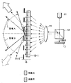
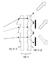
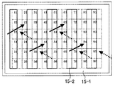
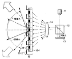
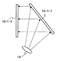
図1は本発明の第1の実施形態に係わる背面投射型表示装置を説明するための概念図である。図1は背面投射型表示装置を上部から見た図である。図2はスクリーン15を透過する変調光の光路を示す説明図である。図3はスクリーンを示す正面図である。なお、図2では投射用レンズにより左側から変調光が右側に放射されるように示されている。
[First Embodiment]
FIG. 1 is a conceptual diagram for explaining a rear projection type display apparatus according to a first embodiment of the present invention. FIG. 1 is a view of a rear projection display device as viewed from above. FIG. 2 is an explanatory diagram showing the optical path of the modulated light that passes through the
図1において、光源11から放射された光が光路途中でP偏光に偏光させ(図示せず)さらに偏光ビームスプリッタ11を透過して反射型液晶素子13に入射する。反射型液晶素子13は、2次元状に配列された画素の奇数列と偶数列とに分けて信号変調を行って変調光を出力する。反射型液晶素子13から放射された光は直線偏光から楕円偏光(あるいは直線偏光)変調され、そのS偏光成分が偏光ビームスプリッタ12内で反射して、投射用レンズ14に入射する。変調の度合いによりS偏光の比率が変化するので、これにより投射レンズに入る各画素からの輝度を制御できることになる。投射用レンズ14を通過した変調光はスクリーン15に投射される。光源11、偏光ビームスプリッタ12及び反射型液晶素子12は画像光生成手段となる。反射型液晶素子13への入射光としてS偏光を用いてもよいが、その場合にはパネルを、図1で偏光ビームスプリッタ11の右位置に設置することになる。
In FIG. 1, light emitted from a
図1〜図3に示すように、スクリーン15は、フレネルレンズ15−1−1と拡散レンズプレート15−1−2からなる投射板15−1と、遮光帯15−2とからなる。フレネルレンズ15−1−1は、投射用レンズ14により投射された変調光を平行な光とし、プレート面に対して垂直な方向に出射する。拡散レンズプレート15−2は、フレネルレンズ15−1からの変調光を拡散して放出する。遮光帯15−2は平板状をなし、投射板15−1の主面に対して平行となるように設けられている。また遮光帯15−2は投射板15−1に投射される奇数列と偶数列との境界上に一つおきに設けられ、左側から見た場合には主に偶数列、右側から見た場合には主に奇数列が見えるように配置される。実線矢印は偶数列の画像が見える領域Aを示し、点線矢印は奇数列の画像が見える領域Bを示す。そして、領域A内で領域Bと重ならない領域が偶数列の画像のみ視認しえる領域となり、領域B内で領域Aと重ならない領域が奇数列の画像のみ視認しえる領域となる。
As shown in FIGS. 1 to 3, the
図3はスクリーンを正面から見た図であり、スクリーンの投射板15−1に投影された液晶パネルの画素(ここでは、6×9の画素を示している)と配置された遮光帯15−2を示している。領域A内で領域Bと重ならない領域(図中左側;実線矢印で示す。)から視聴者がスクリーンを見た場合、画素の偶数列21〜26、41〜46、61〜66、81〜86が見える。一方、領域B内で領域Aと重ならない領域(図中右側;点線矢印で示す。)から視聴者がスクリーンを見た場合、画素の奇数列11〜16、31〜36、51〜56、71〜76、91〜96が見える。
FIG. 3 is a front view of the screen. The liquid crystal panel pixels projected on the projection plate 15-1 of the screen (here, 6 × 9 pixels are shown) and the light shielding band 15- 2 is shown. When the viewer looks at the screen from a region that does not overlap with the region B in the region A (left side in the figure; indicated by a solid arrow), the even columns 21-26, 41-46, 61-66, 81-86 of pixels. Can be seen. On the other hand, when the viewer looks at the screen from the region B that does not overlap with the region A (right side in the figure; indicated by a dotted arrow), the
こうして、図1に示すように、左上側(図3の左側)と左下側(図3の右側)にそれぞれ画像の異なる光が放射され、ディアルビューが可能となる。 In this way, as shown in FIG. 1, light having different images is emitted to the upper left side (left side in FIG. 3) and lower left side (right side in FIG. 3), thereby enabling a dual view.
なお、遮光帯に対して、奇数列及び偶数列がずれて見える場合には、光源11、偏光ビームスプリッタ12、投射用レンズ14からなる投射光学系と、スクリーン15とを機械的に相対的に位置調整する(投射光学系、スクリーンを位置調整する)ことで、ずれを調整することができる。また、又は遮光帯を位置調整してずれを調整することもできる。
When the odd-numbered and even-numbered rows appear to be shifted with respect to the light-shielding band, the projection optical system including the
[第2の実施形態]
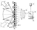
図4は本発明の第2の実施形態に係わる背面投射型表示装置を説明するための概念図である。図4は背面投射型表示装置を上部から見た図である。図1と同一構成部材については同一番号を付し説明を略する。
[Second Embodiment]
FIG. 4 is a conceptual diagram for explaining a rear projection type display apparatus according to the second embodiment of the present invention. FIG. 4 is a view of the rear projection type display device as viewed from above. Constituent members identical to those in FIG.
実施形態1を示す図1の構成では、偶数列の画像が見える領域A、奇数列の画像が見える領域B外では、偶数列の画素列に隣接する奇数列の画素列、又は奇数列に隣接する偶数列の画素行も視認されてしまう。 In the configuration of FIG. 1 showing the first embodiment, outside the region A where the even-numbered image can be seen and the region B where the odd-numbered image can be seen, the odd-numbered pixel row adjacent to the even-numbered pixel row or the odd-numbered row The even-numbered pixel rows are also visually recognized.
図4に示すように、本実施形態ではスクリーン25は、図1の投射板15−1と同じ構成の投射板25−1と、投射板25−1の主面に対して垂直な方向の断面がT字状の遮光帯25−2とからなっている。
As shown in FIG. 4, in this embodiment, the
本実施形態の構成では奇数列と偶数列の組ごとに遮光帯で区切られることになるので、奇数列と偶数列の組に隣接する偶数列、奇数列の画像が認識されることを抑制することができる。 In the configuration of the present embodiment, each pair of odd and even columns is divided by a light shielding band, so that it is possible to suppress recognition of even and odd columns adjacent to the odd and even columns. be able to.
[第3の実施形態]
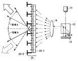
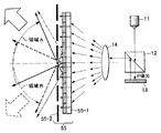
図5は本発明の第3の実施形態に係わる背面投射型表示装置を説明するための概念図である。図5は背面投射型表示装置を上部から見た図である。図1と同一構成部材については同一番号を付し説明を略する。
[Third Embodiment]
FIG. 5 is a conceptual diagram for explaining a rear projection type display apparatus according to the third embodiment of the present invention. FIG. 5 is a view of the rear projection type display device as viewed from above. Constituent members identical to those in FIG.
図5に示すように、本実施形態ではスクリーン35は、図1の遮光帯15−2と同じ構成の遮光帯35−2とを備えているとともに、遮光帯35−2が設けられていない奇数列と偶数列との境界間に第2の遮光帯35−3を備えている。第2の遮光帯は図2の拡散レンズプレート15−1−2に設けられている。投射板35−1には図2に示したフレネルレンズ15−1−1と同じ構成のフレネルレンズが用いられる。
As shown in FIG. 5, in this embodiment, the
本実施形態の構成では、第2の遮光帯が視認され、輝度が減少することになるが、偶数列の画像のみ視認しえる領域及び奇数列の画像のみ視認しえる領域の占有角度が広くなる。 In the configuration of the present embodiment, the second shading band is visually recognized and the luminance is reduced, but the occupation angle of the area where only the even-numbered image is visible and the area where only the odd-numbered image is visible is widened. .
[第4の実施形態]
図6は本発明の第4の実施形態に係わる背面投射型表示装置を説明するための概念図である。図6は背面投射型表示装置を上部から見た図である。図1と同一構成部材については同一番号を付し説明を略する。
[Fourth Embodiment]
FIG. 6 is a conceptual diagram for explaining a rear projection display device according to a fourth embodiment of the present invention. FIG. 6 is a view of the rear projection type display device as viewed from above. Constituent members identical to those in FIG.
図6に示すように、スクリーン45は、図5の遮光帯35−2、第2の遮光帯35−3と同じ構成の遮光帯45−2、第2の遮光帯45−3を備えるとともに、遮光帯45−2が設けられた奇数列と偶数列との境界間に第3の遮光帯45−4を備えている。本実施形態の構成では、第3の実施形態と同様に、偶数列の画像のみ視認しえる領域及び奇数列の画像のみ視認しえる領域の占有角度が広くなる。また、領域A、領域Bを多少はずれても、第3の遮光帯45−4が設けられているために、隣接する奇数列、偶数列が視認されにくくなる。
As shown in FIG. 6, the
[第5の実施形態]
図7は本発明の第5の実施形態に係わる背面投射型表示装置を説明するための概念図である。図7は背面投射型表示装置を上部から見た図である。図1と同一構成部材については同一番号を付し説明を略する。
[Fifth Embodiment]
FIG. 7 is a conceptual diagram for explaining a rear projection type display device according to a fifth embodiment of the present invention. FIG. 7 is a view of the rear projection type display device as viewed from above. Constituent members identical to those in FIG.
図7に示すように、本実施形態は図1に示した第1の実施形態に比べて、遮光帯15−2より幅の長い遮光帯55−2を用いている。投射板55−1は図1に示した投射板15−1と同じ構成である。幅の長い遮光帯55−2を用いることで、輝度が減少することになるが、偶数列の画像のみ視認しえる領域及び奇数列の画像のみ視認しえる領域の占有角度が広くなる。 As shown in FIG. 7, the present embodiment uses a light shielding band 55-2 that is wider than the light shielding band 15-2 as compared to the first embodiment shown in FIG. The projection plate 55-1 has the same configuration as the projection plate 15-1 shown in FIG. Although the luminance is reduced by using the light-shielding band 55-2 having a long width, the occupying angles of the area where only the even-numbered image can be visually recognized and the area where only the odd-numbered image can be visually recognized become wide.
[第6の実施形態]
図8は本発明の第6の実施形態に係わる背面投射型表示装置を説明するための概念図である。図8は背面投射型表示装置を上部から見た図である。図1と同一構成部材については同一番号を付し説明を略する。
[Sixth Embodiment]
FIG. 8 is a conceptual diagram for explaining a rear projection type display apparatus according to a sixth embodiment of the present invention. FIG. 8 is a view of the rear projection type display device as viewed from above. Constituent members identical to those in FIG.
図1に示す構成では、偶数列の画像が見える領域A、奇数列の画像が見える領域B外では、偶数列の画素列に隣接する奇数列の画素列、又は奇数列に隣接する偶数列の画素行も視認されてしまう。 In the configuration shown in FIG. 1, outside the region A where the even-numbered image is visible and the region B where the odd-numbered image is visible, the odd-numbered pixel row adjacent to the even-numbered pixel row or the even-numbered row adjacent to the odd-numbered row The pixel row is also visually recognized.
図8に示すように、本実施形態ではスクリーン65は、図1の投射板15−1と同じ構成の投射板65−1と、投射板65−1の主面に対して垂直な方向に配置された平板状の遮光帯65−2とからなっている。
As shown in FIG. 8, in the present embodiment, the
本実施形態の構成では奇数列と偶数列の組ごとに遮光帯で区切られることになるので、奇数列と偶数列の組に隣接する偶数列、奇数列の画像が認識されることを抑制することができる。 In the configuration of the present embodiment, each pair of odd and even columns is divided by a light shielding band, so that it is possible to suppress recognition of even and odd columns adjacent to the odd and even columns. be able to.
[第7の実施形態]
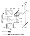
上述した各実施形態では、単色の画像表示の場合については説明したが、図1及び図4〜図8に示した、光源11、偏光ビームスプリッタ12、反射型液晶素子13、投射用レンズ14を、図9に示す投射光学系に変えることで、カラー表示が可能となる。
[Seventh Embodiment]
In each of the above-described embodiments, the case of monochromatic image display has been described. However, the
図9は背面投射型表示装置に用いられるカラー表示用の投射光学系を示す図である。100は白色光源、101はシアンを反射するダイクロイックミラー、102は赤を反射するミラー、103はグリーンを反射するダイクロイックミラーである。104は偏光板、105は偏光ビームスプリッタ、106はグリーンの変調光を形成するための反射型液晶素子である。また、107は偏光板、108は偏光ビームスプリッタ、109はブルーの変調光を形成するための反射型液晶素子、110は偏光板、111は偏光ビームスプリッタ、112はレッドの変調光を形成するための反射型液晶素子である。また、113はダイクロイックプリズムであり、グリーンの変調光を透過し、ブルー及びレッドの変調光を反射して、投射用レンズ114により図1及び図4〜図8のスクリーン15、25〜65に投射する。
FIG. 9 is a diagram showing a projection optical system for color display used in a rear projection type display device.
なお、カラー表示するには、他に液晶表示素子の各画素にRBGのカラーフィルタをのせる方法、カラーホイールを使用してフィールド毎にRGBを切り替えて表示させる方法、RBGのLEDを用いて、フィールド毎にRGBを切り替えて表示させる方法等がある。 In addition, for color display, a method of putting an RBG color filter on each pixel of the liquid crystal display element, a method of switching RGB for each field using a color wheel, and an RBG LED, There is a method of switching and displaying RGB for each field.
[第8の実施形態]
図10は本発明の第8の実施形態に係わる背面投射型表示装置を説明するための概念図である。図10では遮光帯は簡略化のために省略されている。
[Eighth Embodiment]
FIG. 10 is a conceptual diagram for explaining a rear projection type display device according to an eighth embodiment of the present invention. In FIG. 10, the light shielding band is omitted for the sake of simplicity.
本実施形態はフレネルレンズ15−1−1を透過型ではなく反射鏡として、拡散レンズプレート15−1−2と分離させたものである。すなわち、投射用レンズ14から投射した変調光をフレネル反射鏡15−1−3で反射させて平行光とし、拡散レンズプレート15−1−2に放射させたものである。かかる構成により背面投射型表示装置のさらなる小型化を図ることができる。
In the present embodiment, the Fresnel lens 15-1-1 is separated from the diffusing lens plate 15-1-2 as a reflecting mirror instead of a transmission type. That is, the modulated light projected from the
以上説明した各実施形態では、フレネルレンズ15−1−1、拡散レンズプレート151−2は分離して設けられているが、これらを一体化して光学プレート構成することもできる。一体化はプレート同士を貼り合わせたり、1枚の透明プレートの表面、裏面をそれぞれ加工することで実現することができる。例えば、1枚の透明プレートの表面、裏面をそれぞれ加工する場合、フレネルレンズ15−1−1の凹凸を一方の面に形成し、拡散レンズプレート15−1−2の凹凸を他方の面に形成したレンズプレートを作製することができる。プレートどうしの貼り合わせは透明接着剤を用いて行うことができる。 In each of the embodiments described above, the Fresnel lens 15-1-1 and the diffusing lens plate 151-2 are provided separately. However, they can be integrated to form an optical plate. Integration can be realized by bonding the plates together or processing the front and back surfaces of one transparent plate. For example, when processing the front and back surfaces of a single transparent plate, the unevenness of the Fresnel lens 15-1-1 is formed on one surface and the unevenness of the diffusion lens plate 15-1-2 is formed on the other surface. A lens plate can be produced. The plates can be bonded using a transparent adhesive.
以上説明した各実施形態において、視野角の調整を行なえば、3Dも可能である。本実施形態における、左右2画面の使い方は、対戦ゲーム、リビングで2画面で別々のTVを映し出すようにできる。 In each of the embodiments described above, 3D is also possible if the viewing angle is adjusted. In this embodiment, the left and right two screens can be used to display different TVs on the two screens in the battle game and the living room.
以上説明した各実施形態においては、奇数列と偶数列とに分けて画像表示を行う場合につい説明したが奇数行と偶数行とに分けて画像表示する場合にも勿論適用できる。この場合、反射型液晶素子13が2次元状に配列された画素の奇数行と偶数行とに分けて信号変調を行って変調光を出力し、遮光帯で、奇数行と偶数行との境界上を一つおきに遮光するようにすればよい。このような構成では、上下に2画面表示が可能となる。そうすると、例えば、1F、2Fの吹き抜けの場所に設置して、それぞれ異なる映像を表示させることが可能になる。
In each of the embodiments described above, the case where image display is performed separately for odd-numbered columns and even-numbered columns has been described, but the present invention can of course be applied to the case where image display is performed separately for odd-numbered rows and even-numbered rows. In this case, signal modulation is performed separately on the odd-numbered and even-numbered rows of pixels in which the reflective
公共の場所では、広告・宣伝等に利用可能である。喫茶・レストランでは、BGM(Back Ground Movie)としても利用可能である。また劇場等では、2つの映画などを同時に見せることが可能である。 It can be used for advertising and publicity in public places. It can also be used as BGM (Back Ground Movie) at cafes and restaurants. In theaters, it is possible to show two movies at the same time.
また本実施形態において、光学系として、図9に示した3PBS(偏光ビームスプリッタ)以外に、Qaud方式、1PBS方式、を用いても可能である。また、ワイヤグリッドでPBSの機能を代替えすることも可能である。1つの液晶パネルにRGBのカラーフィルタを形成しておけば、6パネルでなく2パネルでRGBカラー表示が可能である。さらに、RBGのカラーLEDを時系列に点灯させれば、カラー表示が可能となる。 In this embodiment, it is also possible to use a Qaud method or a 1PBS method as an optical system other than the 3PBS (polarization beam splitter) shown in FIG. It is also possible to replace the PBS function with a wire grid. If an RGB color filter is formed on one liquid crystal panel, RGB color display is possible with two panels instead of six panels. Furthermore, if the RBG color LEDs are lit in time series, color display is possible.
さらに、投射光学系は反射型液晶素子に限らず、透過型液晶素子やDMD(デジタルマイクロデバイス)を用いたものも利用可能である。 Further, the projection optical system is not limited to the reflective liquid crystal element, but a transmissive liquid crystal element or a device using a DMD (digital microdevice) can also be used.
本発明はディアルビューや3D表示を行う背面投射型表示装置に適用することができる。 The present invention can be applied to a rear projection display device that performs dual view or 3D display.
11 光源
12 偏光ビームスプリッタ
13 反射型液晶素子
14 投射用レンズ
15、25、35、45、55、65 スクリーン
15−1、25−1、35−1、45−1、55−1、65−1 投射板
15−2、25−2、35−2、45−2、55−2、65−2 遮光帯
35−3、45−3、45−4 遮光帯
15−1−1 フレネルレンズ
15−1−2 拡散レンズプレート
DESCRIPTION OF
Claims (14)
前記変調光を投射する光投射手段と、
前記光照射手段からの変調光が背面側に投射されて、奇数列と偶数列、又は奇数行と偶数行からなる変調光が映し出される投射板と、少なくとも、奇数列と偶数列との境界上、又は奇数行と偶数行との境界上を一つおきに遮光する、前記投射板の表示面側に配置された遮光帯と、を含むスクリーンと、
を備えた背面投射型表示装置。 Image light generating means for outputting modulated light by performing signal modulation for display in each of an odd-numbered column and an even-numbered column or an odd-numbered row and an even-numbered row;
Light projection means for projecting the modulated light;
On the boundary between the odd-numbered column and the even-numbered column, at least on the projection plate on which the modulated light from the light irradiation means is projected on the back side and the modulated light consisting of the odd-numbered column and the even-numbered column or the odd-numbered row and the even-numbered row is projected. A screen including a light shielding band arranged on the display surface side of the projection plate, which shields light every other boundary between the odd and even lines,
A rear projection type display device.
前記変調光が背面側に投射されて、奇数列と偶数列、又は奇数行と偶数行からなる変調光が映し出される投射板と、少なくとも、奇数列と偶数列との境界上、又は奇数行と偶数行との境界上を一つおきに遮光する、前記投射板の表示面側に配置された遮光帯とを含むスクリーン。 A screen on which modulated light is incident that has been subjected to signal modulation for display separately in an odd-numbered column and an even-numbered column, or an odd-numbered row and an even-numbered row,
A projection plate on which the modulated light is projected on the back side and the modulated light composed of odd-numbered columns and even-numbered columns or odd-numbered rows and even-numbered rows is projected; and at least on the boundary between the odd-numbered columns and even-numbered columns; A screen including a light-shielding band disposed on the display surface side of the projection plate that shields light every other boundary with an even-numbered line.
Priority Applications (1)
| Application Number | Priority Date | Filing Date | Title |
|---|---|---|---|
| JP2006122047A JP2007293100A (en) | 2006-04-26 | 2006-04-26 | Rear projection display device and screen |
Applications Claiming Priority (1)
| Application Number | Priority Date | Filing Date | Title |
|---|---|---|---|
| JP2006122047A JP2007293100A (en) | 2006-04-26 | 2006-04-26 | Rear projection display device and screen |
Publications (1)
| Publication Number | Publication Date |
|---|---|
| JP2007293100A true JP2007293100A (en) | 2007-11-08 |
Family
ID=38763779
Family Applications (1)
| Application Number | Title | Priority Date | Filing Date |
|---|---|---|---|
| JP2006122047A Pending JP2007293100A (en) | 2006-04-26 | 2006-04-26 | Rear projection display device and screen |
Country Status (1)
| Country | Link |
|---|---|
| JP (1) | JP2007293100A (en) |
Cited By (3)
| Publication number | Priority date | Publication date | Assignee | Title |
|---|---|---|---|---|
| JP2009031692A (en) * | 2007-07-30 | 2009-02-12 | National Institute Of Information & Communication Technology | Image display device |
| JP2014509404A (en) * | 2011-01-31 | 2014-04-17 | ウィジップス | Stereoscopic three-dimensional display screen with integrated photovoltaic cell and method for manufacturing the same |
| WO2016081101A3 (en) * | 2014-11-17 | 2017-05-04 | X Development Llc | Rear projection screen with pin-hole concentrator array |
Citations (5)
| Publication number | Priority date | Publication date | Assignee | Title |
|---|---|---|---|---|
| JPH075455A (en) * | 1992-11-11 | 1995-01-10 | Sharp Corp | display |
| JPH07287195A (en) * | 1994-02-23 | 1995-10-31 | Sanyo Electric Co Ltd | Stereoscopic display device without spectacles |
| JPH085957A (en) * | 1994-06-20 | 1996-01-12 | Sanyo Electric Co Ltd | Stereoscopic display device without spectacles |
| JPH09166762A (en) * | 1995-12-14 | 1997-06-24 | Denso Corp | Streoscopic display device |
| JP2005326803A (en) * | 2003-09-03 | 2005-11-24 | Canon Inc | Stereoscopic image display device |
-
2006
- 2006-04-26 JP JP2006122047A patent/JP2007293100A/en active Pending
Patent Citations (5)
| Publication number | Priority date | Publication date | Assignee | Title |
|---|---|---|---|---|
| JPH075455A (en) * | 1992-11-11 | 1995-01-10 | Sharp Corp | display |
| JPH07287195A (en) * | 1994-02-23 | 1995-10-31 | Sanyo Electric Co Ltd | Stereoscopic display device without spectacles |
| JPH085957A (en) * | 1994-06-20 | 1996-01-12 | Sanyo Electric Co Ltd | Stereoscopic display device without spectacles |
| JPH09166762A (en) * | 1995-12-14 | 1997-06-24 | Denso Corp | Streoscopic display device |
| JP2005326803A (en) * | 2003-09-03 | 2005-11-24 | Canon Inc | Stereoscopic image display device |
Cited By (3)
| Publication number | Priority date | Publication date | Assignee | Title |
|---|---|---|---|---|
| JP2009031692A (en) * | 2007-07-30 | 2009-02-12 | National Institute Of Information & Communication Technology | Image display device |
| JP2014509404A (en) * | 2011-01-31 | 2014-04-17 | ウィジップス | Stereoscopic three-dimensional display screen with integrated photovoltaic cell and method for manufacturing the same |
| WO2016081101A3 (en) * | 2014-11-17 | 2017-05-04 | X Development Llc | Rear projection screen with pin-hole concentrator array |
Similar Documents
| Publication | Publication Date | Title |
|---|---|---|
| US9329470B2 (en) | Display apparatus for displaying multiple view angle images | |
| US7224411B2 (en) | Digital projection equipment and techniques | |
| JP2004062208A (en) | High resolution display with pixel moving means | |
| JP3605572B2 (en) | Three-dimensional image display device, point light emitting member and point light transmitting member | |
| US20130176407A1 (en) | Beam scanned display apparatus and method thereof | |
| JP5707984B2 (en) | projector | |
| JP2016218181A (en) | Projection device using laser beam and head-up display using projection device | |
| JP2004226767A (en) | Optical unit, display system using the same, and image light output method | |
| JP4928152B2 (en) | Rear projection display device and screen | |
| JP2007293100A (en) | Rear projection display device and screen | |
| WO1996021997A2 (en) | 3d-projection | |
| JP2005084374A (en) | Projector and three-dimensional image display system | |
| US7625093B2 (en) | Image display device having a plurality of basic-color projection units | |
| KR101060159B1 (en) | 3D image output method using LCC type projector and apparatus therefor | |
| JP4572347B2 (en) | projector | |
| JPH11295652A (en) | Image display device and projection type image display device using the same | |
| JP2008176140A (en) | Projector and projection adjustment method | |
| JP5630045B2 (en) | Image display device | |
| JP2008102193A (en) | Polarization conversion element, illumination device, and image display device | |
| KR20110071999A (en) | Laser display systems | |
| JP5180677B2 (en) | Illumination device and projection-type image display device using the same | |
| JP2012181417A (en) | Projector and projection system | |
| JP3238993B2 (en) | 3D image display device | |
| JP2009282553A (en) | projector | |
| JP2010128139A (en) | Image display apparatus, image display method, and image display system |
Legal Events
| Date | Code | Title | Description |
|---|---|---|---|
| RD04 | Notification of resignation of power of attorney |
Free format text: JAPANESE INTERMEDIATE CODE: A7424 Effective date: 20080207 |
|
| RD01 | Notification of change of attorney |
Free format text: JAPANESE INTERMEDIATE CODE: A7421 Effective date: 20090220 |
|
| A621 | Written request for application examination |
Free format text: JAPANESE INTERMEDIATE CODE: A621 Effective date: 20090427 |
|
| RD04 | Notification of resignation of power of attorney |
Free format text: JAPANESE INTERMEDIATE CODE: A7424 Effective date: 20100201 |
|
| RD01 | Notification of change of attorney |
Free format text: JAPANESE INTERMEDIATE CODE: A7421 Effective date: 20100630 |
|
| A131 | Notification of reasons for refusal |
Free format text: JAPANESE INTERMEDIATE CODE: A131 Effective date: 20111108 |
|
| A521 | Written amendment |
Free format text: JAPANESE INTERMEDIATE CODE: A523 Effective date: 20120110 |
|
| A131 | Notification of reasons for refusal |
Free format text: JAPANESE INTERMEDIATE CODE: A131 Effective date: 20120131 |
|
| A521 | Written amendment |
Free format text: JAPANESE INTERMEDIATE CODE: A523 Effective date: 20120329 |
|
| A02 | Decision of refusal |
Free format text: JAPANESE INTERMEDIATE CODE: A02 Effective date: 20120626 |