EP0597239B1 - Yarn brake - Google Patents
Yarn brake Download PDFInfo
- Publication number
- EP0597239B1 EP0597239B1 EP93115994A EP93115994A EP0597239B1 EP 0597239 B1 EP0597239 B1 EP 0597239B1 EP 93115994 A EP93115994 A EP 93115994A EP 93115994 A EP93115994 A EP 93115994A EP 0597239 B1 EP0597239 B1 EP 0597239B1
- Authority
- EP
- European Patent Office
- Prior art keywords
- section
- braking
- thread
- circumferential
- abutment
- Prior art date
- Legal status (The legal status is an assumption and is not a legal conclusion. Google has not performed a legal analysis and makes no representation as to the accuracy of the status listed.)
- Expired - Lifetime
Links
- 238000003780 insertion Methods 0.000 claims abstract description 5
- 230000037431 insertion Effects 0.000 claims abstract description 5
- 238000000034 method Methods 0.000 claims description 5
- 238000004804 winding Methods 0.000 claims description 5
- 238000009941 weaving Methods 0.000 abstract description 2
- 230000005284 excitation Effects 0.000 description 9
- 230000007704 transition Effects 0.000 description 5
- 238000011161 development Methods 0.000 description 2
- 230000018109 developmental process Effects 0.000 description 2
- 230000000694 effects Effects 0.000 description 2
- 230000005415 magnetization Effects 0.000 description 2
- 230000002093 peripheral effect Effects 0.000 description 2
- 230000001133 acceleration Effects 0.000 description 1
- XAGFODPZIPBFFR-UHFFFAOYSA-N aluminium Chemical compound [Al] XAGFODPZIPBFFR-UHFFFAOYSA-N 0.000 description 1
- 229910052782 aluminium Inorganic materials 0.000 description 1
- 238000001816 cooling Methods 0.000 description 1
- 238000006073 displacement reaction Methods 0.000 description 1
- 239000000428 dust Substances 0.000 description 1
- 239000002245 particle Substances 0.000 description 1
- 230000010287 polarization Effects 0.000 description 1
Images


Classifications
-
- D—TEXTILES; PAPER
- D03—WEAVING
- D03D—WOVEN FABRICS; METHODS OF WEAVING; LOOMS
- D03D47/00—Looms in which bulk supply of weft does not pass through shed, e.g. shuttleless looms, gripper shuttle looms, dummy shuttle looms
- D03D47/34—Handling the weft between bulk storage and weft-inserting means
-
- B—PERFORMING OPERATIONS; TRANSPORTING
- B65—CONVEYING; PACKING; STORING; HANDLING THIN OR FILAMENTARY MATERIAL
- B65H—HANDLING THIN OR FILAMENTARY MATERIAL, e.g. SHEETS, WEBS, CABLES
- B65H59/00—Adjusting or controlling tension in filamentary material, e.g. for preventing snarling; Applications of tension indicators
- B65H59/10—Adjusting or controlling tension in filamentary material, e.g. for preventing snarling; Applications of tension indicators by devices acting on running material and not associated with supply or take-up devices
- B65H59/20—Co-operating surfaces mounted for relative movement
- B65H59/22—Co-operating surfaces mounted for relative movement and arranged to apply pressure to material
-
- B—PERFORMING OPERATIONS; TRANSPORTING
- B65—CONVEYING; PACKING; STORING; HANDLING THIN OR FILAMENTARY MATERIAL
- B65H—HANDLING THIN OR FILAMENTARY MATERIAL, e.g. SHEETS, WEBS, CABLES
- B65H2555/00—Actuating means
- B65H2555/20—Actuating means angular
- B65H2555/23—Actuating means angular magnetic, e.g. rotary solenoids
-
- B—PERFORMING OPERATIONS; TRANSPORTING
- B65—CONVEYING; PACKING; STORING; HANDLING THIN OR FILAMENTARY MATERIAL
- B65H—HANDLING THIN OR FILAMENTARY MATERIAL, e.g. SHEETS, WEBS, CABLES
- B65H2555/00—Actuating means
- B65H2555/20—Actuating means angular
- B65H2555/24—Servomotors
-
- B—PERFORMING OPERATIONS; TRANSPORTING
- B65—CONVEYING; PACKING; STORING; HANDLING THIN OR FILAMENTARY MATERIAL
- B65H—HANDLING THIN OR FILAMENTARY MATERIAL, e.g. SHEETS, WEBS, CABLES
- B65H2701/00—Handled material; Storage means
- B65H2701/30—Handled filamentary material
- B65H2701/31—Textiles threads or artificial strands of filaments
Definitions
- the invention relates to a device for variable braking of running threads, wires or the like, in particular for use in weft insertion on weaving machines. And a method for operating such a thread brake.
- a thread brake is known from French patent application FR-A-23 75 366.
- the thread is passed between two brake parts that can be brought together in a resilient manner.
- One of the two brake parts is fixed and not resilient and the other brake part is cushioned and movable relative to the fixed brake part, so that the thread braking can be varied in its strength by a change in the spring tension achieved as a result of the movement.
- the resilient brake part can also be spaced apart from the fixed brake part via a push rod via a push rod, so that an unbraked thread run can be achieved.
- the problem with such a thread brake is that the spring force has to be relatively strong in order to brake the thread effectively.
- the resilient braking part in order to achieve a free running of the thread, the resilient braking part must be completely lifted off the fixed braking part.
- the spring of the resilient brake part must be at least partially relaxed. This results in relatively high displacement paths of the push rod driving the resilient element. There are also limits to such an arrangement with regard to the cycle times between braking and releasing the thread, since the relaxation of the spring can no longer follow high cycle frequencies.
- the model for the invention was also the device for the different braking of running threads, which is not part of the prior art and was proposed in the non-prepublished utility model DE-U-91 13 430.
- Such a device was also disclosed in document EP-A-0 524 429 belonging to the prior art according to Article 54 (3) EPC.
- the device shown there already shows a fixed leaf spring which is acted upon by a cylindrical brake part.
- This brake part is driven by an electric motor and has a cylindrical first section, the circumferential surface of which holds the spring in a pretension in the release position of the thread run.
- a second section of the body has a peripheral section that is reduced in cross section. The thread runs between this second section and the leaf spring.
- the thread is unbraked. After a further angular amount of further rotation of the rotatable body, the thread is acted upon by the non-reduced cross-sectional circumferential section of the second section, so that the thread-braking position is achieved, the thread being clamped between the leaf spring and the cylinder surface.
- This device works in cyclical operation, with the drive motor running back and forth between two stops. In order to achieve a high clock frequency, the motor must both be driven at high acceleration and braked strongly. The use of mechanical stops for braking the motor, for example, is not optimal.
- the object of the invention is to improve the performance of such a thread brake.
- the device specified in claim 1 and the method specified in claim 6 are proposed.
- the subclaims represent advantageous developments of the invention.
- the resilient braking part no longer needs to be moved during operation to vary the braking.
- Due to the essentially cylindrical first section of circular cross-section the spring element is constantly held in a prestress, which can be varied by adjusting means.
- the second section which can also be brought into contact with the spring element, has in the circumferential direction at least one reduced cross-sectional circumferential section, which is reduced in cross-section to the extent that a window remains between the circumferential section and the spring element when it is opposite the spring element, through which the thread can be pulled off without braking.
- the shaft of the electric motor can be gradually rotated further without mechanical stops having to be provided.
- the stepper motor then only needs to be rotated by a corresponding number of steps, which is done by a corresponding number of switching impulses until the reduced cross-sectional reduced circumferential area is opposite the spring element and the thread brake position is reached.
- a preferably curved leaf spring can serve as a spring element and at the same time as a thread guide.
- Another preferred embodiment is one in which a plurality of circumferentially reduced circumferential surfaces are provided in the circumferential direction.
- Circumferential areas not reduced in cross section are provided between these reduced-area circumferential surfaces.
- a thread-free position occurs when a circumferentially reduced cross-sectional area is placed opposite the spring element, while when a circumferential area that is not reduced in cross-section is placed opposite, the thread is clamped between the counter-bearing and the spring element.
- the embodiment of the invention in which the number of steps of the stepping motor corresponds to at least twice the number of circumferentially reduced cross-sectional sections is considered to be particularly advantageous. As a result of this configuration, the stepper motor needs Transition from a braking position to a release position can only be switched by a single step.
- the number of steps of the motor is four. That means with every step the shaft of the stepper motor is turned through 90 °. In total, four steps are necessary to make one revolution of the shaft of the stepper motor.
- the invention proposes in a further development that these circumferential sections are designed as flattenings arranged transversely to the radial. The transitions to the circumferential sections which are adjacent in the circumferential direction and are not reduced in cross-section could be rounded in order to protect the thread.
- the stepper motor preferably has a magnetically polarized armature.
- this armature can be formed from a permanent magnet. The orientation of the magnet is oriented radially to the axis.
- this preferred stepper motor has an excitation coil running in the circumferential direction, which is subdivided into a number of partial windings which corresponds to the number of steps of the electric motor.
- the annular coil core of the excitation coil Associated with the individual step positions of the electric motor, has opposite pole pairs. The armature of the electric motor is oriented between these pole pairs in accordance with the polarization of the excitation coil.
- the excitation coil consists of an annular coil core with a total of four poles, each offset by 90 °, between which poles a partial winding is provided and if the armature is to be held between two of these poles by magnetic forces, the partial windings arranged between these two opposite poles are polarized in the same direction, so that a magnetization parallel to the armature magnetic field is built up. If the armature is now to be rotated one step, in this case by 90 °, the second pole pair lying transverse to the first pole pair is magnetized accordingly. Now the partial windings lying between these two poles are traversed by current in the same direction, so that a magnetic field aligned between these two magnetic poles is created.
- the method for operating a thread brake in accordance with a device includes that with each step of the stepping motor, the thread brake alternates from a braking position into a release position, starting from a braking position corresponding to a step position of the electric motor, in which a non-reduced circumferential area is opposite to the spring element, in the subsequent step of the electric motor a cross-section-reduced area is brought opposite to the spring element.
- the direction of rotation of the electric motor need not change after the transition from the braking position to the release position.
- the electric motor can always turn in the same direction operate. This enables the armature to be magnetically bonded in any step position.
- the body forming the counter bearing is rotated clockwise, step by step.
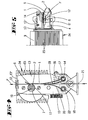
- the device shown in FIGS. 1 to 5 has an engine block 24 which is formed on the outside with cooling fins 23.
- the engine block is made of aluminum.
- a motor shaft (not shown in FIGS. 1 to 5) emerges on one side of the engine block and carries an essentially cylindrical body 2.
- the cylindrically shaped body 2 forms the counter bearing to a resilient tab 1, which thread F in the braking position between itself and the counter bearing 2 (Fig. 2) jammed.
- the tab 1 is carried by a substantially U-shaped carrier plate 13 which is screwed onto the motor housing 24 with its bottom surface. The bottom surface of the carrier 13 is penetrated by the shaft of the motor.
- Thread take-off opening 12 thread brake and thread inlet opening 21 lie almost on a straight line.
- the above-mentioned pre-brake consists of two brackets 19, 20 which are spring-loaded against one another and which are each screwed onto square axes 18, 14.
- the two tabs are screwed onto opposite surfaces of the square 14.
- All three spring elements 1, 19, 20 have essentially the same rigidity and the same width, which cover the sections 4, 5, 8 of the body 2.
- the section 8 is located between the sections 4, 5 of the body 2 which have a circular cross section.
- the section 8 has two opposite circumferential sections 6, 7 with reduced cross sections in the circumferential direction. These circumferential sections are formed by flats which are arranged essentially transversely to the radial and which, in the transition region to the sections 10, 11 of the body 2 which are not reduced in cross section, have roundings 6 ', not shown in the drawings.
- the cross-section-reducing circumferential sections 6, 7 form windows through which the thread can be drawn off without friction in the release position (cf. FIGS. 4 and 5).
- the pre-brake consisting of the leaf springs 20 and 19 can be deactivated by appropriately adjusting the setting wheel 22 and pivoting the spring tabs 19, 10, namely by spacing the resilient tab 20 from the resilient tab 19.
- the first section of the substantially cylindrical body forming the counterbearing consists of two circular sections 4, 5.
- These circular sections 4, 5 have the effect that, even in a position according to FIGS. 4 and 5, the leaf spring 1 is in a prestressed manner Location remains.
- the sections 4 and 5 run horizontally to the axis of rotation of the body 2.
- a minimal change in the position of the spring 1 takes place in the braking position (see FIGS. 2 and 3), namely when the thread between one of the circumferential sections 10 or 11 not reduced in cross section and the Tab 1 is pinched.
- the tab can be deflected by the thickness of the thread F. This is accompanied by a lifting of the tab 1 from the two Observe circular sections 4 and 5 in cross section.
- the operation of the device is as follows: The thread runs from the inlet eyelet 21 through the brake and is drawn off by the draw-off eyelet 12 and fed to a loom or the like, not shown.
- the resilient tab 1 is acted upon by the circumferential section 11 of the second section 8, which section is not reduced in cross-section, with the thread F being clamped in.
- the thread is braked in this position. In this position, the thread is not drawn off, but is held at a certain thread tension only on the part of the thread insertion eyelet 21.
- the body 2 is displaced by 90 °, as a result of which the thread's release position shown in FIGS. 4 and 5 is reached.
- the thread can now be pulled out without braking.
- the reduced-cross-sectional circumferential section 6 now has an opposite position to the leaf spring 1. Since the reduction in cross-section is many times larger than the diameter of the thread, it can be pulled off almost frictionlessly in the window formed by the reduction in cross-section. Because of the circular sections 4 and 5 which act on the tab 1 in this position, the tab 1 remains essentially in the same position.
- stepper motor which is arranged in the motor housing 23 and is designated by the reference number 9. This stepper motor has a step number of four. This means that the shaft is rotated 90 ° with each step. Each step of the stepper motor thus corresponds to a transition from a braking position to a release position or vice versa.
- the structure of the stepping motor 9 is shown schematically in FIG. 6.
- the armature 44 which is designed as a permanent magnet oriented transversely to the axis of rotation, sits on the shaft 43, which is rotatably mounted in the motor housing.
- the armature is surrounded by an annular core 30 of an excitation coil.
- the excitation coil consists of a total of four partial areas each comprising an angle of 90 °.
- Each sub-area has a sub-coil 31, 32, 33, 34 and an inwardly projecting pole 39, 40, 41, 42.
- the partial coils 31, 32, 33, 34 are arranged between the four poles 39, 40, 41, 42, each offset by 90 °.
- the ends of adjacent coils - for example those of the coils 31 and 32 - are connected to one another, the respective ends 31 "being connected to the ends 32 '.
- the connecting position of the coils 31, 32, 33, 34 form electrical connection contacts 35, 36, 37, 38 out.
- the corresponding electrical connections 35 and 37 are to be subjected to voltage current in such a way that a magnetic field aligned parallel to the magnetic field of the armature 44 is built up by the excitation coil.
- the electrical connections 36 and 38 must accordingly be supplied with voltage current, so that a magnetic field builds up between the poles 40 and 42. If a corresponding magnetic field is then built up between the opposing poles 40 and 42, the armature 44 endeavors to orient itself in this magnetic field in accordance with its magnetization. As a result, the armature 44 makes a 90 ° clockwise rotation. The north pole and south pole of the armature are thereby shifted out of the orientation to the likewise opposite poles 39 and 41.
- the armature is bound in the magnetic field built up by the excitation coil, the armature is prevented from rotating due to its angular momentum. As soon as the armature rotates beyond the equilibrium position parallel to the excitation magnetic field, the angle of the two magnetic fields causes the armature to return to its equilibrium position. This restoring force quasi forms an electromagnetic stop.
Abstract
Description
Die Erfindung betrifft eine Vorrichtung zur variablen Bremsung laufender Fäden, Drähte oder dergleichen, insbesondere zum Einsatz beim Schußeintrag an Webmaschinen. Und ein Verfahren zum Betrieb einer derartigen Fadenbremse.The invention relates to a device for variable braking of running threads, wires or the like, in particular for use in weft insertion on weaving machines. And a method for operating such a thread brake.
Eine Fadenbremse ist aus der französischen Patentanmeldung FR-A-23 75 366 bekannt. Dort wird der Faden zwischen zwei federnd zueinander bringbaren Bremsteilen hindurchgeführt. Eines der beiden Bremsteile ist fest und nicht federnd vorgesehen und das andere Bremsteil ist abgefedert und gegenüber dem festen Bremsteil beweglich, so daß die Fadenbremsung durch eine zufolge der Bewegung erzielten Änderung der Federspannung in ihrer Stärke variierbar ist. Das federnde Bremsteil ist zufolge eines Nockenscheiben-Kipphebelantriebs über eine Stößelstange auch vom festen Bremsteil beabstandbar, so daß ein ungebremster Fadenlauf erzielbar ist. Problematisch bei einer derartigen Fadenbremse ist, daß die Federkraft relativ stark sein muß, um den Faden wirksam zu bremsen. Andererseits muß zur Erzielung eines Freilaufs des Fadens das federnde Bremsteil vollständig vom festen Bremsteil abgehoben werden. Dabei muß die Feder des federnden Bremsteils zumindest teilweise entspannt werden. Dies hat relativ hohe Verlagerungswege der das federnde Element antreibende Stößelstange zur Folge. Auch sind einer solchen Anordnung hinsichtlich der Zykluszeiten zwischen Bremsen und Freigeben des Fadens Grenzen gesetzt, da die Entspannung der Feder hohen Zyklus-Frequenzen nicht mehr folgen kann.A thread brake is known from French patent application FR-A-23 75 366. There, the thread is passed between two brake parts that can be brought together in a resilient manner. One of the two brake parts is fixed and not resilient and the other brake part is cushioned and movable relative to the fixed brake part, so that the thread braking can be varied in its strength by a change in the spring tension achieved as a result of the movement. The resilient brake part can also be spaced apart from the fixed brake part via a push rod via a push rod, so that an unbraked thread run can be achieved. The problem with such a thread brake is that the spring force has to be relatively strong in order to brake the thread effectively. On the other hand, in order to achieve a free running of the thread, the resilient braking part must be completely lifted off the fixed braking part. The spring of the resilient brake part must be at least partially relaxed. This results in relatively high displacement paths of the push rod driving the resilient element. There are also limits to such an arrangement with regard to the cycle times between braking and releasing the thread, since the relaxation of the spring can no longer follow high cycle frequencies.
Aus der europäischen Patentanmeldung EP-A-0 384 502 ist weiter eine Fadenbremse bekannt, bei der ein rotationsbewegliches nicht federndes Bremsteil eine vorgespannte federnde Lasche beaufschlagt. Bei dieser Anordnung ist jedoch kein zyklisches Ändern der Fadenbremsung vorgesehen. Der sich drehende, das niaht federnde Bremsteil ausbildende Zylinderkörper dient lediglich dazu, vermittels Reibung auf dem Faden aufliegende Staubpartikel zu entfernen.From the European patent application EP-A-0 384 502 a thread brake is also known in which a rotationally movable non-resilient brake part acts on a prestressed resilient tab. With this arrangement, however, no cyclical changing of the thread braking is provided. The rotating cylinder body, which forms the seam of the brake element, merely serves to remove dust particles lying on the thread by means of friction.
Vorbild für die Erfindung war auch die in dem nicht vorveröffentlichten Gebrauchsmuster DE-U-91 13 430 vorgeschlagene nicht zum Stand der Technik zählende Vorrichtung zur unterschiedlichen Bremsung laufender Fäden. Eine solche Vorrichtung war auch im zum Stand der Technik gemäß Artikel 54(3) EPÜ gehörenden Dokument EP-A-0 524 429 offenbart. Die dort dargestellte Vorrichtung zeigt bereits eine feststehende Blattfeder, die von einem zylinderförmigen Bremsteil beaufschlagt wird. Dieses Bremsteil wird von einem Elektromotor angetrieben und weist einen zylindrischen ersten Abschnitt auf, dessen Umfangsfläche die Feder in der Freigabestellung des Fadenlaufes in einer Vorspannung hält. Ein zweiter Teilabschnitt des Körpers weist einen Umfangsabschnitt auf, der querschnittsreduziert ist. Zwischen diesem zweiten Teilabschnitt und der Blattfeder läuft der Faden hindurch. Ist der zylindrische Körper dem Fenster zur Blattfeder hin ausgerichtet, so ist der Faden ungebremst. Nach einer um einen bestimmten Winkelbetrag erfolgten Weiterdrehung des drehbaren Körpers wird der Faden von dem nicht querschnittsreduzierten Umfangsabschnitt des zweiten Teilabschnitts beaufschlagt, so daß die fadenbremsende Stellung erzielt wird, wobei der Faden zwischen der Blattfeder und der Zylinderoberfläche eingeklemmt ist. Diese Vorrichtung arbeitet im Taktbetrieb, wobei der Antriebsmotor zwischen zwei Anschlägen hin- und zurückläuft. Zur Erzielung einer hohen Taktfrequenz muß der Motor sowohl stark beschleunigt angetrieben als auch stark abgebremst werden. Die Verwendung von beispielsweise mechanischen Anschlägen zur Bremsung des Motors sind nicht optimal.The model for the invention was also the device for the different braking of running threads, which is not part of the prior art and was proposed in the non-prepublished utility model DE-U-91 13 430. Such a device was also disclosed in document EP-A-0 524 429 belonging to the prior art according to Article 54 (3) EPC. The device shown there already shows a fixed leaf spring which is acted upon by a cylindrical brake part. This brake part is driven by an electric motor and has a cylindrical first section, the circumferential surface of which holds the spring in a pretension in the release position of the thread run. A second section of the body has a peripheral section that is reduced in cross section. The thread runs between this second section and the leaf spring. If the cylindrical body is aligned with the window towards the leaf spring, the thread is unbraked. After a further angular amount of further rotation of the rotatable body, the thread is acted upon by the non-reduced cross-sectional circumferential section of the second section, so that the thread-braking position is achieved, the thread being clamped between the leaf spring and the cylinder surface. This device works in cyclical operation, with the drive motor running back and forth between two stops. In order to achieve a high clock frequency, the motor must both be driven at high acceleration and braked strongly. The use of mechanical stops for braking the motor, for example, is not optimal.
Ausgehend von der in der eingangs genannten europäischen Patentschrift EP-A-0 384 502 bekannten Vorrichtung liegt der Erfindung die Aufgabe zugrunde, eine derartige Fadenbremse hinsichtlich ihrer Leistungsfähigkeit zu verbessern.Starting from the device known in the aforementioned European patent EP-A-0 384 502, the object of the invention is to improve the performance of such a thread brake.
Zur Lösung der Aufgabe wird die im Anspruch 1 angegebene Vorrichtung und das im Anspruch 6 angegebene Verfahren vorgeschlagen. Die Unteransprüche stellen vorteilhafte Weiterbildungen der Erfindung dar. Zufolge der Ausgestaltung der Erfindung braucht das federnde Bremsteil zur Variierung der Bremsung im Betrieb nicht mehr bewegt werden. Vermöge des im wesentlichen zylindrischen ersten Teilabschnitts kreisförmigen Querschnitts wird das Federelement ständig in einer ggf. durch Einstellmittel variierbaren Vorspannung gehalten. Der zweite Teilabschnitt, welcher ebenfalls in Auflage zum Federelement gebracht werden kann, besitzt in Umfangsrichtung mindestens einen querschnittsreduzierten Umfangsabschnitt, der soweit querschnittsreduziert ist, daß bei dessen Gegenüberlage zum Federelement ein Fenster zwischen Umfangsabschnitt und Federelement verbleibt, durch welches der Faden ungebremst abgezogen werden kann. Nach einer Weiterdrehung des von einem, im wesentlichen zylinderförmig ausgebildeten Gegenlagers tritt dann ein nicht querschnittsreduzierter Umfangsabschnitt in Gegenüberlage zum Federelement, so daß der Faden zwischen Federelement und dem das Gegenlager bildenden im wesentlichen zylindrischen Körpers eingeklemmt wird, was eine Bremsung zur Folge hat. Hierbei kann vorgesehen sein, daß sich die Blattfeder um die Dicke des Fadens verlagert. Zufolge der Vorbremse ist auch bei geöffneter Fadenbremse eine gewisse, separat einstellbare Bremskraft gegeben. Ist der erste Teilabschnitt des im wesentlichen zylinderförmigen Gegenlagers exakt kreisförmig, und geht der nicht querschnittsreduzierte Umfangsabschnitt des zweiten Teilabschnitts fluchtend in diesen ersten Teilabschnitt über, so erfolgt beim Eintreten der Vorrichtung in die Bremsstellung eine Auslenkung des Federelementes um eine Fadendikke. Zufolge der Ausbildung des Gegenlager-Antriebsteiles als einen elektrischen Schrittmotor ist ein schrittweises Weiterdrehen der Welle des Elektromotors, ohne daß mechanische Anschläge vorgesehen werden müssen, möglich. Ausgehend aus einer Fadenfreigabestellung, bei der der querschnittsreduzierte Umfangsabschnitt dem Federelement gegenüberliegt, braucht der Schrittmotor dann nur um eine entsprechende Anzahl von Schritten weitergedreht zu werden, was durch eine entsprechende Anzahl von Schaltimpulsen geschieht, bis der nicht mehr querschnittsreduzierte Umfangsbereich in Gegenüberlage zum Federelement tritt und die Fadenbremsstellung erreicht ist. Hierbei kann eine bevorzugt gebogen ausgestaltete Blattfeder als Federelement und gleichzeitig als Fadenführung dienen. Bevorzugt ist weiterhin eine Ausgestaltung, bei der in Umfangsrichtung eine Vielzahl von querschnittsreduzierten Umfangsflächen vorgesehen ist. Zwischen diesen querschnittsreduzierten Umfangsflächen sind jeweils nicht querschnittsreduzierte Umfangsbereiche vorgesehen. Auch hier tritt bei Gegenüberlage einer querschnittsreduzierten Umfangsfläche zum Federelement eine Fadenfreigangsstellung ein, während bei Gegenüberlage eines nicht querschnittsreduzierten Umfangsbereichs der Faden zwischen dem Gegenlager und dem Federelement eingeklemmt wird. Als besonders vorteilhaft wird die Ausbildung der Erfindung angesehen, bei der die Schrittzahl des Schrittmotors mindestens dem Doppelten der Anzahl der querschnittsreduzierten Umfangsabschnitte entspricht. Zufolge dieser Ausgestaltung braucht der Schrittmotor zum Übergang einer Bremsstellung in eine Freigabestellung jeweils nur um einen einzelnen Schritt weitergeschaltet werden. Sind beispielsweise zwei querschnittsreduzierte Umfangsflächen vorgesehen, die in vorteilhafter Weise gegenüberliegend angeordnet sind, zwischen welchen sich entsprechende sich ebenfalls gegenüberliegende nicht querschnittsreduzierte Umfangsbereiche befinden, so beträgt die Schrittzahl des Motor vier. Das heißt mit jedem Schritt wird die Welle des Schrittmotors um 90° weitergedreht. Insgesamt sind also zur Durchführung einer Umdrehung der Welle des Schrittmotors vier Schritte notwendig. Zur Ausgestaltung der querschnittreduzierten Umfangsabschnitte schlägt die Erfindung in einer Weiterbildung vor, daß diese Umfangsabschnitte als quer zur Radialen angeordnete Abflachungen ausgebildet sind. Die Übergänge zu den jeweils in Umfangsrichtung benachbart liegenden nicht querschnittsreduzierten Umfangsabschnitte könnten dabei um den Faden zu schonen, abgerundet sein. Der Schrittmotor weist bevorzugt einen magnetisch polarisierten Anker auf. Dieser Anker kann in einer einfachsten Ausgestaltung aus einem Permanentmagneten gebildet sein. Dabei ist die Orientierung des Magneten radial zur Achse ausgerichtet. Um den Anker herum weist dieser bevorzugte Schrittmotor eine in Umfangsrichtung verlaufende Erregerspule auf, welche in eine Anzahl von Teilwicklungen unterteilt ist, die der Anzahl der Schrittzahl des Elektromotors entspricht. Den einzelnen Schrittstellungen des Elektromotor zugeordnet weist der ringförmige Spulenkern der Erregerspule gegenüberliegende Polpaare auf. Zwischen diesen Polpaaren orientiert sich der Anker des Elektromotors entsprechend der Polarisierung der Erregerspule. Besteht beispielsweise die Erregerspule aus einem ringförmigen Spulenkern mit insgesamt vier, jeweils um 90° versetzt angeordneten Polen, zwischen welchen Polen jeweils eine Teilwicklung vorgesehen ist, und soll der Anker zwischen zwei dieser Pole durch magnetische Kräfte gehalten werden, so werden die zwischen diesen beiden gegenüberliegenden Pole angeordneten Teilwicklungen gleichsinnig polarisiert, so daß eine zum Ankermagnetfeld parallele Magnetisierung aufgebaut wird. Soll nun der Anker um einen Schritt, in diesem Falle um 90° weitergedreht werden, so wird das quer zum ersten Polpaar liegende zweite Polpaar entsprechend magnetisiert. Nunmehr werden die zwischen diesen beiden Polen liegende Teilwindungen in gleicher Richtung von Strom durchflossen, so daß ein zwischen diesen beiden Magnetpolen ausgerichtetes Magnetfeld entsteht. Sobald diese neue Strombeaufschlagung erfolgt ist, orientiert sich der Anker entsprechend dem gedrehten Magnetfeld in seine neue Position. Ein Weiterdrehen des aus der alten Stellung in die neue Stellung beschleunigten Ankers wird durch magnetischen Haltekräfte verhindert. Es ist somit ein magnetischer Anschlag gegeben, der den Anker am Weiterdrehen hindert. Dieser Anschlag ist um so größer, je größer das Magnetfeld ist.To achieve the object, the device specified in
Das Verfahren zum Betreiben einer Fadenbremse entsprechend einer erfindungsgemäßen Vorrichtung beinhaltet, daß bei jedem Schritt des Schrittmotors die Fadenbremse abwechselnd von einer Brems- in eine Freigabestellung übergeht, wobei ausgehend von einer mit einer Schrittstellung des Elektromotors korrespondierenden Bremsstellung, in welcher ein nicht reduzierter Umfangsbereich in Gegenüberlage zum Federelement tritt, beim folgenden Schritt des Elektromotors ein querschnittsreduzierter Bereich in Gegenüberlage zum Federelement gebracht wird. Zufolge dieser Verfahrensschritte braucht sich der Drehsinn des Elektromotors nach dem Übergang von der Bremsstellung in die Freigabestellung nicht zu ändern. Der Elektromotor kann dagegen mit immer demselben Drehsinn betrieben werden. Dies ermöglicht die magnetische Fesselung des Ankers in jeder Schrittstellung. Der das Gegenlager bildende Körper wird dabei taktend gedreht, und zwar Schritt für Schritt.The method for operating a thread brake in accordance with a device according to the invention includes that with each step of the stepping motor, the thread brake alternates from a braking position into a release position, starting from a braking position corresponding to a step position of the electric motor, in which a non-reduced circumferential area is opposite to the spring element, in the subsequent step of the electric motor a cross-section-reduced area is brought opposite to the spring element. As a result of these method steps, the direction of rotation of the electric motor need not change after the transition from the braking position to the release position. The electric motor, however, can always turn in the same direction operate. This enables the armature to be magnetically bonded in any step position. The body forming the counter bearing is rotated clockwise, step by step.
Anhand der beigefügten Zeichnungen wird ein Ausführungsbeispiel der Erfindung im folgenden erläutert. Es zeigt:
- Fig. 1
- eine perspektivische Darstellung einer erfindungsgemäßen Fadenbremse;
- Fig. 2
- eine Draufsicht auf eine Vorrichtung nach Fig. 1 in Bremsstellung;
- Fig. 3
- eine Seitenansicht einer Vorrichtung gemäß Fig. 1 in Bremsstellung;
- Fig. 4
- eine Darstellung gemäß Fig. 2 in Freigabestellung;
- Fig. 5
- eine Darstellung gemäß Fig. 3 in Freigabestellung;
- Fig. 6
- eine schematische Darstellung eines vierpoligen Schrittmotors.
- Fig. 1
- a perspective view of a thread brake according to the invention;
- Fig. 2
- a plan view of a device of Figure 1 in the braking position.
- Fig. 3
- a side view of a device according to Figure 1 in the braking position.
- Fig. 4
- a representation of Figure 2 in the release position.
- Fig. 5
- a representation of Figure 3 in the release position.
- Fig. 6
- is a schematic representation of a four-pole stepper motor.
Die in den Fig. 1 bis 5 dargestellte Vorrichtung weist einen Motorblock 24 auf, der außenseitig mit Kühlrippen 23 ausgebildet ist. Der Motorblock ist aus Aluminium ausgebildet. Einseitig aus dem Motorblock tritt eine in den Fig. 1 bis 5 nicht dargestellte Motorwelle aus, die einen im wesentlichen zylindrisch geformten Körper 2 trägt. Der zylindrisch geformte Körper 2 bildet das Gegenlager zu einer federnden Lasche 1, welche zwischen sich und dem Gegenlager 2 den Faden F in der Bremsstellung (Fig. 2) einklemmt. Getragen wird die Lasche 1 von einem im wesentlichen U-förmig ausgebildeten Trägerblech 13, das mit seiner Bodenfläche auf dem Motorgehäuse 24 aufgeschraubt ist. Die Bodenfläche des Trägers 13 wird von der Welle des Motors durchsetzt.The device shown in FIGS. 1 to 5 has an
An einem der U-Schenkel 13' des Trägers 13 befindet sich eine Fadenabzugsöse 12, durch welche der durch die Fadenöffnung 21 des gegenüberliegenden U-Schenkels einlaufende Faden F abgezogen wird, nachdem er durch die von den beiden gegenüberliegenden Laschen 19 und 20 ausgebildete Vorbremse und die eigentliche Fadenbremse, ausgebildet von der Lasche 1 und dem Körper 2, gezogen wird.On one of the U-legs 13 'of the
Fadenabzugsöffnung 12, Fadenbremse und Fadeneinlauföffnung 21 liegen nahezu auf einer Geraden.Thread take-
Die obengenannte Vorbremse besteht aus zwei gegeneinander abgefederte Laschen 19, 20, welche jeweils an Vierkantachsen 18, 14 angeschraubt sind. Dabei ist die Vierkantachse 18, die etwa in Gegenüberlage zur Vierkantachse 14 mittels eines Einstellrades 22, schwenkbar verstellbar. Der ebenfalls über die Einstellscheibe 50 und das Schneckengetriebe 16, 17 schwenkbar verstellbare Vierkantträger 14 trägt neben der Lasche 19 noch die Lasche 1. Die beiden Laschen sind dabei an sich gegenüberliegenden Flächen des Vierkants 14 angeschraubt. Durch Verstellen des Einstellrades 15 kann somit die Stärke der Auflage der Federlasche 1 auf dem Gegenlager 2 eingestellt werden. Mit dem Einstellrad 22 kann die Stärke der Vorbremse durch Spannen des Federblattes 20 eingestellt werden.The above-mentioned pre-brake consists of two
Alle drei Federelemente 1, 19, 20 haben im wesentlichen die gleiche Steifigkeit und die gleiche Breite, welche die Teilabschnitte 4, 5, 8 des Körpers 2 überdecken. Zwischen den einen kreisförmigen Querschnitt aufweisenden Teilabschnitten 4, 5 des Körpers 2 befindet sich der Teilabschnitt 8. Der Teilabschnitt 8 weist in Umfangsrichtung jeweils zwei gegenüberliegende querschnittsreduzierte Umfangsabschnitte 6, 7 auf. Diese Umfangsabschnitte werden von im wesentlichen quer zur Radialen angeordnete Abflachungen ausgebildet, die im Übergangsbereich zu den nicht querschnittsreduzierten Abschnitten 10, 11 des Körpers 2 in den Zeichnungen nicht dargestellte Abrundungen 6' aufweisen. Die querschnittsreduzierenden Umfangsabschnitte 6, 7 bilden Fenster aus, durch die in der Freigabestellung (vgl. Fig. 4 und 5) der Faden reibungsfrei abgezogen werden kann.All three
Die aus den Blattfedern 20 und 19 bestehende Vorbremse kann durch entsprechendes Verstellen des Einstellrades 22 und Verschwenken der Federlaschen 19, 10 außer Wirkung gebracht werden, indem nämlich die federnde Lasche 20 von der federnden Lasche 19 beabstandet wird.The pre-brake consisting of the
Gemäß dem dargestellten Ausführungsbeispiel besteht der erste Teilabschnitt des das Gegenlager bildende, im wesentlichen zylindrischen Körpers aus zwei kreisförmigen Abschnitten 4, 5. Diese kreisförmigen Abschnitte 4, 5 bewirken, daß auch bei einer Stellung gemäß Fig. 4 und 5 die Blattfeder 1 in einer vorgespannten Lage verbleibt. Die Abschnitte 4 und 5 verlaufen horizontal zur Drehachse des Körpers 2. Eine minimale Änderung der Lage der Feder 1 erfolgt in der Bremsstellung (vgl. Fig. 2 und 3), wenn nämlich der Faden zwischen einer der nicht querschnittsreduzierten Umfangabschnitte 10 oder 11 und der Lasche 1 eingeklemmt wird. Die Lasche kann dabei um die Dicke des Fadens F ausgelenkt werden. Dabei ist einhergehend auch ein Abheben der Lasche 1 von den beiden im Querschnitt kreisförmigen Abschnitten 4 und 5 zu beobachten.According to the exemplary embodiment shown, the first section of the substantially cylindrical body forming the counterbearing consists of two
Die Wirkungsweise der Vorrichtung ist die Folgende: Der Faden läuft von der Einlauföse 21 durch die Bremse hindurch und wird durch die Abzugsöse 12 abgezogen und einem nicht dargestellten Webstuhl oder dergleichen zugeführt. In der in Fig. 2 und 3 dargestellten Stellung des Körpers 2 wird die federnde Lasche 1 von dem nicht querschnittsreduzierten Umfangsabschnitt 11 des zweiten Teilabschnitts 8 unter Einklemmen des Fadens F beaufschlagt. Der Faden ist in dieser Stellung gebremst. In dieser Stellung wird der Faden nicht abgezogen, sondern nur auf seiten der Fadeneinführungsöse 21 auf einer gewissen Fadenspannung gehalten. Wird der Faden dagegen aus der Fadenabzugsöse 12 abgezogen, so wird der Körper 2 um 90° verlagert, wodurch die in den Fig. 4 und 5 dargestellte Freigabestellung des Fadens erreicht wird. Abgesehen von der Wirkung der Vorbremse kann der Faden nun ungebremst abgezogen werden. In der in den Fig. 4 und 5 dargestellten Stellung weist nun der querschnittsreduzierte Umfangsabschnitt 6 eine Gegenüberlage zur Blattfeder 1 auf. Da die Querschnittsreduzierung um ein Vielfaches größer ist als der Durchmesser des Fadens, kann dieser in dem von der Querschnittsreduzierung ausgebildeten Fenster nahezu reibungsfrei abgezogen werden. Wegen der kreisförmigen Abschnitte 4 und 5, die in dieser Position die Lasche 1 beaufschlagen, bleibt diese im wesentlichen in der gleichen Stellung ruhen.The operation of the device is as follows: The thread runs from the
Durch fortlaufendes, dem gleichen Drehsinn beibehaltendes, jeweils um eine 90° Drehung weiter Verlagern des Körpers 2, wird dann abwechselnd jeweils eine Brems- und eine Freigabestellung des Fadens eingenommen. Die Drehrichtung kann dabei parallel zum Fadenlauf oder gegen den Fadenlauf eingestellt werden.Dieses getakelte Weiterschalten des Körpers 2 wird durch einen Schrittmotor bewirkt, der im Motorgehäuse 23 angeordnet ist und mit der Bezugsziffer 9 bezeichnet ist. Dieser Schrittmotor hat eine Schrittzahl von vier. Das bedeutet, daß mit jedem Schritt eine 90° Drehung der Welle durchgeführt wird. Jeder Schritt des Schrittmotors korrespondiert somit zu einem Übergang aus einer Bremsstellung in eine Freigabestellung oder umgekehrt.By continuously shifting the
In Fig. 6 ist schematisch der Aufbau des Schrittmotors 9 dargestellt. Der Anker 44, welcher als quer zur Drehachse orientierter Permanentmagnet ausgebildet ist, sitzt auf der Welle 43, welche drehbar im Motorgehäuse gelagert ist. Der Anker ist umgeben von einem ringförmigen Kern 30 einer Erregerspule. Die Erregerspule besteht aus insgesamt vier jeweils einen Winkel von 90° umfassende Teilbereiche. Jeder Teilbereich weist eine Teilspule 31, 32, 33, 34 und einen nach innen ragenden Pol 39, 40, 41, 42 auf. Die Teilspulen 31, 32, 33, 34 sind zwischen den vier jeweils um 90° versetzt liegenden Polen 39, 40, 41, 42 angeordnet. Die Enden jeweils benachbarter Spulen - beispielsweise die der Spulen 31 und 32 - sind miteinander verbunden, wobei die jeweiligen Enden 31" verbunden sind mit den Enden 32'. Die Verbindungsstellung der Spulen 31, 32, 33, 34 bilden elektrische Anschlußkontakte 35, 36, 37, 38 aus.The structure of the stepping
Soll beispielsweise der in der Fig. 6 dargestellte Zustand fixiert sein, d.h. der Anker 44 mit seinem Nordpol zum Pol 39 zeigen bzw. mit seinem Südpol zum Pol 41, so sind die entsprechenden elektrischen Anschlüsse 35 und 37 derart mit Spannungsstrom zu beaufschlagen, daß ein parallel zum Magnetfeld des Ankers 44 ausgerichtetes Magnetfeld von der Erregerspule aufgebaut wird.If, for example, the state shown in FIG. 6 is to be fixed, ie the
Soll mit dem Schrittmotor 9 ein aus der Fig. 6 dargestellten Stellung ein Schritt in Uhrzeigerrichtung durchgeführt werden, so müssen entsprechend die elektrischen Anschlüsse 36 und 38 mit Spannungsstrom beaufschlagt werden, so daß sich ein Magnetfeld zwischen den Polen 40 und 42 aufbaut. Ist zwischen den gegenüberliegenden Polen 40 und 42 sodann ein entsprechendes Magnetfeld aufgebaut, so ist der Anker 44 bestrebt, entsprechend seiner Magnetisierung sich in diesem Magnetfeld zu orientieren. Dies hat zur Folge, daß der Anker 44 eine 90° Drehung im Uhrzeigersinn durchführt. Nordpol und Südpol des Ankers werden dadurch aus der Orientierung zu den ebenfalls gegenüberliegenden Polen 39 und 41 heraus verlagert.If a position shown in FIG. 6 is to be carried out clockwise with the
Wegen der Fesselung des Ankers in dem von der Erregerspule aufgebauten Magnetfeld ist ein sich Weiterdrehen des Ankers vermöge seines Drehimpulses verhindert. Sobald sich der Anker über die Gleichgewichtslage parallel zum Erregermagnetfeld hinaus fortdreht, bewirkt der Winkel der beiden Magnetfelder ein Rückstellmoment des Ankers in seine Gleichgewichtslage. Diese Rückstellungskraft bildet quasi einen elektromagnetischen Anschlag aus.Because the armature is bound in the magnetic field built up by the excitation coil, the armature is prevented from rotating due to its angular momentum. As soon as the armature rotates beyond the equilibrium position parallel to the excitation magnetic field, the angle of the two magnetic fields causes the armature to return to its equilibrium position. This restoring force quasi forms an electromagnetic stop.
Durch getaktetes Wechseln der Spannungsbeaufschlagung der elektrischen Anschlüsse 35, 36, 37, 38 wird demnach ein getaktetes Drehfeld erzeugt, dem der Anker entsprechend folgt.By clocked changing of the voltage applied to the
Claims (6)
- Device for variably braking moving threads, wires or the like, in particular for use during weft insertion on looms, wherein the thread (F) passes through between two braking members which can be brought into spring contact with each other and of which one forms a spring element and the other an abutment and one of the braking members is movable to vary the braking, wherein the abutment is constructed as an essentially cylindrical body (2) which is acted upon by the spring element (1) rotatably, wherein a section (8) of the cylindrical body (2) comprises at least one circumferential region of reduced cross-section (6, 7) and wherein a preliminary brake comprising two plates pivotably adjustable about their bearing spindles (18, 11) is provided.
- Device for variably braking moving threads, wires or the like according to claim 1, characterised in that in the circumferential direction of the body (2) are provided a plurality of circumferential sections of reduced cross-section (6, 7) between which is provided in each case an unreduced circumferential cross-section (10, 11).
- Device for variably braking moving threads, wires or the like according to claim 1 or 2, characterised in that the abutment is mounted on the shaft (1) of an electric motor designed as a stepping motor (9), and in that the number of steps of the electric motor (9) corresponds to a multiple, preferably twice the number of circumferential sections of reduced cross-section (6, 7).
- Device for variably braking moving threads, wires or the like according to any of the preceding claims, characterised in that the circumferential section of reduced cross-section is constructed as a flattened portion (6, 7) arranged transversely to the radial.
- Device for variably braking moving threads, wires or the like according to claim 3 or 4, characterised in that the stepping motor (9) comprises an armature (44) which is magnetically polarised, preferably formed by a permanent magnet, and which is surrounded by an annular exciting coil which consists of a number of partial windings (31, 32, 33, 34) corresponding to the number of steps of the electric motor and of which the core forms pairs of magnetic poles (39, 41, 40, 42) associated with the step positions of the armature.
- Method for the operation of a thread brake for variably braking moving threads, wires or the like, in particular for use during weft insertion on looms, wherein the thread (F) passes through between two braking members which can be brought into spring contact with each other and of which one forms a spring element and the other an abutment and one of the braking members is movable to vary the braking, wherein the abutment is constructed as an essentially cylindrical body (2) which is acted upon by the spring element (1) rotatably, with a first partial section (4, 5) of essentially circular cross-section and a second partial section (8) comprising at least one circumferential region of reduced cross-section (6, 7), wherein the abutment is mounted on the shaft (1) of an electric motor designed as a stepping motor (9), according to any of claims 1 to 5, characterised in that, while retaining the direction of rotation of the motor, at each step the thread brake changes alternately from a braking position to a thread release position, wherein, starting from a braking position which corresponds to a step position of the electric motor and in which a circumferential region of unreduced cross-section (10, 11) is located opposite the spring element (1), at the next step of the electric motor a region of reduced cross-section (6, 7) is brought opposite the plate (1).
Applications Claiming Priority (2)
| Application Number | Priority Date | Filing Date | Title |
|---|---|---|---|
| DE9215226U DE9215226U1 (en) | 1992-11-09 | 1992-11-09 | Thread brake |
| DE9215226U | 1992-11-09 |
Publications (2)
| Publication Number | Publication Date |
|---|---|
| EP0597239A1 EP0597239A1 (en) | 1994-05-18 |
| EP0597239B1 true EP0597239B1 (en) | 1996-05-29 |
Family
ID=6885817
Family Applications (1)
| Application Number | Title | Priority Date | Filing Date |
|---|---|---|---|
| EP93115994A Expired - Lifetime EP0597239B1 (en) | 1992-11-09 | 1993-10-04 | Yarn brake |
Country Status (6)
| Country | Link |
|---|---|
| US (1) | US5492286A (en) |
| EP (1) | EP0597239B1 (en) |
| JP (1) | JP3439244B2 (en) |
| AT (1) | ATE138698T1 (en) |
| DE (2) | DE9215226U1 (en) |
| ES (1) | ES2053418T3 (en) |
Families Citing this family (16)
| Publication number | Priority date | Publication date | Assignee | Title |
|---|---|---|---|---|
| BE1011089A3 (en) * | 1997-04-07 | 1999-04-06 | Picanol Nv | Yarn brake WITH TWO brake elements. |
| SE9900665D0 (en) * | 1999-02-23 | 1999-02-23 | Iro Patent Ag | Device and methods for varying brake current running fadens |
| BE1012559A3 (en) * | 1999-03-17 | 2000-12-05 | Wiele Michel Van De Nv | Weft thread tensioner for a loom |
| DE19919122A1 (en) | 1999-04-27 | 2000-11-02 | Iro Patent Ag Baar | Actuator and thread brake with one actuator |
| DE60017667T2 (en) * | 1999-10-26 | 2005-07-07 | L.G.L. Electronics S.P.A., Gandino | Weft brake, in particular for weaving machines |
| DE10013625A1 (en) | 2000-03-18 | 2001-09-27 | Dornier Gmbh Lindauer | Thread brake, in particular weft brake for weaving machines |
| US7543610B2 (en) * | 2006-06-16 | 2009-06-09 | Sultex Ag | Thread clamp for a rapier head |
| US6755366B2 (en) * | 2002-09-30 | 2004-06-29 | Solutia Inc. | Device for direct insertion of yarn in automatic winder |
| US20040195425A1 (en) * | 2003-03-05 | 2004-10-07 | Johannes Jensen | Yarn tensioning device and arrays thereof |
| JP4003710B2 (en) * | 2003-07-23 | 2007-11-07 | 株式会社豊田自動織機 | Weft insertion control device in jet loom |
| EP1811068B1 (en) * | 2006-01-24 | 2009-06-17 | Sultex AG | Controlled weft brake |
| WO2009025803A1 (en) | 2007-08-20 | 2009-02-26 | Kevin Kremeyer | Energy-deposition systems, equipment and methods for modifying and controlling shock waves and supersonic flow |
| JP2012062186A (en) * | 2010-09-17 | 2012-03-29 | Fuji Xerox Co Ltd | Document transporting device and image forming apparatus |
| US9809414B2 (en) * | 2012-04-24 | 2017-11-07 | Curt G. Joa, Inc. | Elastic break brake apparatus and method for minimizing broken elastic rethreading |
| US10669653B2 (en) * | 2015-06-18 | 2020-06-02 | Kevin Kremeyer | Directed energy deposition to facilitate high speed applications |
| CN110817596A (en) * | 2019-12-04 | 2020-02-21 | 芜湖航天特种电缆厂股份有限公司 | Preheating device before cable rolling |
Family Cites Families (13)
| Publication number | Priority date | Publication date | Assignee | Title |
|---|---|---|---|---|
| US2952393A (en) * | 1957-05-06 | 1960-09-13 | Charles G Newton | Yarn tension compensator |
| DE2131302A1 (en) * | 1971-06-24 | 1972-12-28 | Dornier Gmbh Lindauer | Thread brake for textile machines |
| JPS5381758A (en) * | 1976-12-27 | 1978-07-19 | Nissan Motor | Device for gripping weft on shuttleless loom |
| US4249580A (en) * | 1979-09-20 | 1981-02-10 | Rockwell International Corporation | Weft control device |
| DE3446567C1 (en) * | 1984-12-20 | 1986-05-07 | Lindauer Dornier Gmbh, 8990 Lindau | Weft brake with gradually controllable braking effect |
| US4969489A (en) * | 1988-07-14 | 1990-11-13 | Nissan Motor Co., Ltd. | Weft threading system for fluid jet loom using the storage drum winding arm |
| BE1002841A3 (en) * | 1989-02-16 | 1991-06-25 | Picanol N V Naamloze Vennoosch | Device for braking a weft thread in a weaving machine. |
| US5002089A (en) * | 1990-04-02 | 1991-03-26 | Carrier Corporation | Variable area refrigerant expansion device for heating mode of a heat pump |
| BE1004140A3 (en) * | 1990-04-17 | 1992-09-29 | Picanol Nv | Thread brake. |
| DE59105505D1 (en) * | 1990-09-10 | 1995-06-22 | Rueti Ag Maschf | Thread brake for weaving machines. |
| DE9113430U1 (en) * | 1991-07-22 | 1992-12-24 | Sobrevin Societe De Brevets Industriels-Etablissement, Vaduz, Li | |
| BE1005173A3 (en) * | 1991-08-13 | 1993-05-11 | Picanol Nv | Thread brake. |
| CH686955A5 (en) * | 1992-03-16 | 1996-08-15 | Der Loepfe Ag Geb | Yarn braking device. |
-
1992
- 1992-11-09 DE DE9215226U patent/DE9215226U1/en not_active Expired - Lifetime
-
1993
- 1993-10-04 DE DE59302741T patent/DE59302741D1/en not_active Expired - Fee Related
- 1993-10-04 EP EP93115994A patent/EP0597239B1/en not_active Expired - Lifetime
- 1993-10-04 ES ES93115994T patent/ES2053418T3/en not_active Expired - Lifetime
- 1993-10-04 AT AT93115994T patent/ATE138698T1/en active
- 1993-10-07 US US08/133,523 patent/US5492286A/en not_active Expired - Fee Related
- 1993-11-09 JP JP30346293A patent/JP3439244B2/en not_active Expired - Fee Related
Also Published As
| Publication number | Publication date |
|---|---|
| US5492286A (en) | 1996-02-20 |
| EP0597239A1 (en) | 1994-05-18 |
| ES2053418T1 (en) | 1994-08-01 |
| JP3439244B2 (en) | 2003-08-25 |
| JPH06278943A (en) | 1994-10-04 |
| ATE138698T1 (en) | 1996-06-15 |
| DE9215226U1 (en) | 1994-05-11 |
| DE59302741D1 (en) | 1996-07-04 |
| ES2053418T3 (en) | 1996-07-16 |
Similar Documents
| Publication | Publication Date | Title |
|---|---|---|
| EP0597239B1 (en) | Yarn brake | |
| DE19743314A1 (en) | Brushless motor with permanent magnet rotor e.g. for powering motor vehicle | |
| DE4025754A1 (en) | PERMANENT MAGNETIC MOTOR | |
| EP0772703B1 (en) | Selvage-forming device for a mechanical loom | |
| DE2906795A1 (en) | PULSER | |
| DE60108317T2 (en) | Device for polarizing a permanent magnet rotor | |
| EP0422539A1 (en) | Electrical machine with a rotor and a stator | |
| DE3612289A1 (en) | MAGNETICALLY ACTUATED ACTUATOR | |
| EP1732088B1 (en) | Electromagnetic actuator | |
| EP3487049A1 (en) | Linear motor comprising a transversal flux | |
| DE7527207U (en) | ELECTRIC ACTUATOR | |
| WO1999049115A2 (en) | Device for forming a gauze edge using a motor comprising a rotor and a stator for housing said rotor | |
| DE2452131B2 (en) | Small electric motor | |
| DE602004012756T2 (en) | NONLINEAR SPRING POWER ASSEMBLY | |
| DE1932641C3 (en) | Stepping motor that can be switched by means of direct current pulses of alternating polarity | |
| WO2001042079A1 (en) | Electromagnetic machine for a vehicle, especially a bicycle | |
| DE3931484C2 (en) | ||
| DE3712652C2 (en) | ||
| EP0151497B1 (en) | Single-phase synchronous motor with a two-pole permanent magnetic rotor | |
| DE102019110951A1 (en) | Method and device for assembling and / or disassembling a permanent magnet motor | |
| DE2929475C2 (en) | DC unipolar machine | |
| EP0924843A1 (en) | Apparatus for winding a thread on a bobbin | |
| DE102006036685A1 (en) | Magnetic actuator for direct generation of a rotary actuating movement of a shaft with currentless end position fixation | |
| DE19725743C1 (en) | Method of controlling an electrical stepper motor | |
| DE3005921A1 (en) | Monostable rotary armature system - uses soft magnetic armature with inserted permanent magnet having pole which is adjacent armature pole |
Legal Events
| Date | Code | Title | Description |
|---|---|---|---|
| PUAI | Public reference made under article 153(3) epc to a published international application that has entered the european phase |
Free format text: ORIGINAL CODE: 0009012 |
|
| AK | Designated contracting states |
Kind code of ref document: A1 Designated state(s): AT BE CH DE ES FR GB IT LI NL SE |
|
| ITCL | It: translation for ep claims filed |
Representative=s name: STUDIO JAUMANN |
|
| EL | Fr: translation of claims filed | ||
| GBC | Gb: translation of claims filed (gb section 78(7)/1977) | ||
| 17P | Request for examination filed |
Effective date: 19940727 |
|
| 17Q | First examination report despatched |
Effective date: 19950704 |
|
| GRAH | Despatch of communication of intention to grant a patent |
Free format text: ORIGINAL CODE: EPIDOS IGRA |
|
| GRAA | (expected) grant |
Free format text: ORIGINAL CODE: 0009210 |
|
| AK | Designated contracting states |
Kind code of ref document: B1 Designated state(s): AT BE CH DE ES FR GB IT LI NL SE |
|
| REF | Corresponds to: |
Ref document number: 138698 Country of ref document: AT Date of ref document: 19960615 Kind code of ref document: T |
|
| REG | Reference to a national code |
Ref country code: CH Ref legal event code: NV Representative=s name: R. A. EGLI & CO. PATENTANWAELTE |
|
| REG | Reference to a national code |
Ref country code: ES Ref legal event code: BA2A Ref document number: 2053418 Country of ref document: ES Kind code of ref document: T3 |
|
| ET | Fr: translation filed | ||
| REF | Corresponds to: |
Ref document number: 59302741 Country of ref document: DE Date of ref document: 19960704 |
|
| GBT | Gb: translation of ep patent filed (gb section 77(6)(a)/1977) |
Effective date: 19960606 |
|
| REG | Reference to a national code |
Ref country code: ES Ref legal event code: FG2A Ref document number: 2053418 Country of ref document: ES Kind code of ref document: T3 |
|
| ITF | It: translation for a ep patent filed |
Owner name: STUDIO JAUMANN |
|
| PG25 | Lapsed in a contracting state [announced via postgrant information from national office to epo] |
Ref country code: AT Effective date: 19961004 |
|
| PLBE | No opposition filed within time limit |
Free format text: ORIGINAL CODE: 0009261 |
|
| STAA | Information on the status of an ep patent application or granted ep patent |
Free format text: STATUS: NO OPPOSITION FILED WITHIN TIME LIMIT |
|
| 26N | No opposition filed | ||
| PGFP | Annual fee paid to national office [announced via postgrant information from national office to epo] |
Ref country code: GB Payment date: 19970805 Year of fee payment: 5 |
|
| PGFP | Annual fee paid to national office [announced via postgrant information from national office to epo] |
Ref country code: ES Payment date: 19971017 Year of fee payment: 5 |
|
| PG25 | Lapsed in a contracting state [announced via postgrant information from national office to epo] |
Ref country code: GB Free format text: LAPSE BECAUSE OF NON-PAYMENT OF DUE FEES Effective date: 19981004 |
|
| PG25 | Lapsed in a contracting state [announced via postgrant information from national office to epo] |
Ref country code: ES Free format text: LAPSE BECAUSE OF EXPIRATION OF PROTECTION Effective date: 19981005 |
|
| GBPC | Gb: european patent ceased through non-payment of renewal fee |
Effective date: 19981004 |
|
| PGFP | Annual fee paid to national office [announced via postgrant information from national office to epo] |
Ref country code: FR Payment date: 19991018 Year of fee payment: 7 |
|
| PGFP | Annual fee paid to national office [announced via postgrant information from national office to epo] |
Ref country code: SE Payment date: 19991025 Year of fee payment: 7 |
|
| PG25 | Lapsed in a contracting state [announced via postgrant information from national office to epo] |
Ref country code: SE Free format text: THE PATENT HAS BEEN ANNULLED BY A DECISION OF A NATIONAL AUTHORITY Effective date: 20001030 |
|
| REG | Reference to a national code |
Ref country code: ES Ref legal event code: FD2A Effective date: 20010201 |
|
| EUG | Se: european patent has lapsed |
Ref document number: 93115994.1 |
|
| PG25 | Lapsed in a contracting state [announced via postgrant information from national office to epo] |
Ref country code: FR Free format text: LAPSE BECAUSE OF NON-PAYMENT OF DUE FEES Effective date: 20010629 |
|
| REG | Reference to a national code |
Ref country code: FR Ref legal event code: ST |
|
| PGFP | Annual fee paid to national office [announced via postgrant information from national office to epo] |
Ref country code: BE Payment date: 20011022 Year of fee payment: 9 |
|
| PGFP | Annual fee paid to national office [announced via postgrant information from national office to epo] |
Ref country code: NL Payment date: 20011026 Year of fee payment: 9 |
|
| PGFP | Annual fee paid to national office [announced via postgrant information from national office to epo] |
Ref country code: CH Payment date: 20011102 Year of fee payment: 9 |
|
| PGFP | Annual fee paid to national office [announced via postgrant information from national office to epo] |
Ref country code: DE Payment date: 20011129 Year of fee payment: 9 |
|
| PG25 | Lapsed in a contracting state [announced via postgrant information from national office to epo] |
Ref country code: LI Free format text: LAPSE BECAUSE OF NON-PAYMENT OF DUE FEES Effective date: 20021031 Ref country code: CH Free format text: LAPSE BECAUSE OF NON-PAYMENT OF DUE FEES Effective date: 20021031 Ref country code: BE Free format text: LAPSE BECAUSE OF NON-PAYMENT OF DUE FEES Effective date: 20021031 |
|
| BERE | Be: lapsed |
Owner name: SOC. DE BREVETS INDUSTRIELS-ETABLISSEMENT *SOBREVI Effective date: 20021031 |
|
| PG25 | Lapsed in a contracting state [announced via postgrant information from national office to epo] |
Ref country code: NL Free format text: LAPSE BECAUSE OF NON-PAYMENT OF DUE FEES Effective date: 20030501 Ref country code: DE Free format text: LAPSE BECAUSE OF NON-PAYMENT OF DUE FEES Effective date: 20030501 |
|
| REG | Reference to a national code |
Ref country code: CH Ref legal event code: PL |
|
| NLV4 | Nl: lapsed or anulled due to non-payment of the annual fee |
Effective date: 20030501 |
|
| PGFP | Annual fee paid to national office [announced via postgrant information from national office to epo] |
Ref country code: IT Payment date: 20081022 Year of fee payment: 16 |
|
| PG25 | Lapsed in a contracting state [announced via postgrant information from national office to epo] |
Ref country code: IT Free format text: LAPSE BECAUSE OF NON-PAYMENT OF DUE FEES Effective date: 20091004 |