EP1732088B1 - Electromagnetic actuator - Google Patents
Electromagnetic actuator Download PDFInfo
- Publication number
- EP1732088B1 EP1732088B1 EP06113990.3A EP06113990A EP1732088B1 EP 1732088 B1 EP1732088 B1 EP 1732088B1 EP 06113990 A EP06113990 A EP 06113990A EP 1732088 B1 EP1732088 B1 EP 1732088B1
- Authority
- EP
- European Patent Office
- Prior art keywords
- armature
- coils
- pole
- end positions
- actuator drive
- Prior art date
- Legal status (The legal status is an assumption and is not a legal conclusion. Google has not performed a legal analysis and makes no representation as to the accuracy of the status listed.)
- Expired - Fee Related
Links
Images

Classifications
-
- F—MECHANICAL ENGINEERING; LIGHTING; HEATING; WEAPONS; BLASTING
- F01—MACHINES OR ENGINES IN GENERAL; ENGINE PLANTS IN GENERAL; STEAM ENGINES
- F01L—CYCLICALLY OPERATING VALVES FOR MACHINES OR ENGINES
- F01L9/00—Valve-gear or valve arrangements actuated non-mechanically
- F01L9/20—Valve-gear or valve arrangements actuated non-mechanically by electric means
-
- H—ELECTRICITY
- H01—ELECTRIC ELEMENTS
- H01F—MAGNETS; INDUCTANCES; TRANSFORMERS; SELECTION OF MATERIALS FOR THEIR MAGNETIC PROPERTIES
- H01F7/00—Magnets
- H01F7/06—Electromagnets; Actuators including electromagnets
- H01F7/08—Electromagnets; Actuators including electromagnets with armatures
- H01F7/14—Pivoting armatures
- H01F7/145—Rotary electromagnets with variable gap
Definitions
- the present invention relates to an electromagnetic actuator for adjusting an actuator between at least three positions, with the features of the preamble of claim 1.
- Actuators of this type can be used, for example, to actuate an air cycle valve in the intake of an internal combustion engine, with the help of a pulse charging the engine can be achieved.
- an actuator preferably has to be switched within very short switching times between two different switching positions.
- a use of such an actuator for adjusting gas exchange valves in piston engines is conceivable.
- an actuator of the type mentioned is known, which is equipped with a soft magnetic anchor.
- This armature is drive-coupled with an actuator and has multiple anchor surfaces.
- the actuator has a plurality of soft magnetic Pole elements on which have a plurality of pole faces, where the armature surfaces come into contact in two end positions of the armature.
- a restoring device is provided, which drives the armature by means of spring force in a lying between the end positions starting position. With the help of a holding device, the armature can now be fixed in its end positions by means of electromagnetic forces.
- the present invention is concerned with the problem of providing for such an actuator improved or at least another embodiment, which is characterized in particular by a simplified and preferably inexpensive manufacturability.
- the invention is based on the general idea of producing the electromagnetic forces required for holding the armature in its end positions by means of a plurality of coils, wherein adjacent coils are polarized in opposite directions to generate these forces. In this way it is possible to involve all coils in the generation of the electromagnetic forces for fixing the armature in the respective end position.
- the invention makes use of the knowledge that a single coil for generating the required electromagnetic forces must be subjected to comparatively high currents, which on the one hand entails higher losses and a relatively strong generation of heat.
- a correspondingly complex power electronics is required to control the large currents. Such power electronics in turn is comparatively expensive, consumes even comparatively much energy and generates correspondingly much waste heat.
- the required electromagnetic forces with multiple coils can be realized at significantly lower currents within the individual coils, thereby reducing losses and heat generation.
- the electronics required for switching or controlling the coils only have to switch comparatively small currents, so that they can be realized correspondingly simply and inexpensively, while having a comparatively low own power requirement and a correspondingly low Heat development shows.
- the actuator according to the invention requires multiple coils, it can be realized at a lower cost due to the advantages shown at the end than the known actuator, which has only a single coil.
- the pole elements and the armature are coordinated so that forms a closed magnetic circuit in each end position of the armature, which connects adjacent pole elements via the armature with each other. Extremely high holding forces with comparatively low currents can be realized in the end positions with the aid of the magnetic closure realized via the armature. This is particularly advantageous in terms of heat generation.
- the holding device in both end positions of the armature energizes the coils for fixing the armature with a constant polarity.
- the energization of the coils short-term
- the energization of the coils is turned off, so that the armature of the one end position associated pole faces can lift, but the coils are assigned to generate the holding force to the other end position Pole surfaces not reversed, but only re-energized with the same polarity.
- the energy remaining in the coils when switched off can be used.
- the required electromagnetic forces can be generated faster in this way.
- the power or energy requirement of the actuator decreases.
- the electronics simplify controlling or regulating the coil energization.
- the armature is arranged in an armature space and the coils are each arranged in a coil space open to the armature space. Furthermore, the coils and the armature space are matched to one another in such a way that the coils can be inserted into the armature space in a finished wound state with the armature removed and from there into the respective coil space.
- This design has the great advantage that the individual coils can be completely wound and finished in the course of a pre-assembly, so that in a final assembly only the finished coils must be inserted into the coil spaces. Compared to a conventional construction, in which the respective coils must be wound directly on the pole element, this means a considerable simplification. Accordingly, the actuator according to the invention can be produced particularly inexpensively.
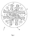
- an inventive electromagnetic actuator 1 comprises an armature 2, which is drive-coupled in a manner not shown with an actuator, also not shown.
- the armature 2 is rotatably mounted on a shaft 3, which is rotatably mounted about a rotation axis 4.
- the shaft 3 is then non-rotatably connected, for example, with the actuator, not shown, so that via the shaft 3, the armature 2 is drive-coupled to the actuator.
- the actuator 1 is characterized in particular by extremely short switching times.
- the actuator may be a valve or a flap or any other actuator that is to be switched at relatively high speed or with extremely short switching times between at least two switching positions.
- the actuator 1 is a high-speed actuator for actuating an air-cycle valve, which is arranged in an intake tract. The air cycle valve is then driven by the actuator 1 for adjusting actuator.
- a high-speed actuator for example, from the DE 101 40 706 A1 known.
- the armature 2 has a plurality of anchor surfaces 5 and 6. In the illustrated preferred embodiment, a total of eight anchor surfaces 5, 6 are provided, namely four first anchor surfaces 5 and four second anchor surfaces 6.
- the anchor 2 is made of a soft magnetic material.
- the actuator 1 on several pole elements 7, which also consist of a soft magnetic material.
- a circumferential distribution of the pole elements 7 which is uniform relative to the axis of rotation 4 is preferred.
- These pole elements 7 have a plurality of pole faces 8, 9.
- exactly four pole elements 7 are provided, which have a total of eight pole faces 8, 9, namely four first pole faces 8 and four second pole faces 9.
- the anchor faces 5, 6 come into two end positions of the anchor 2 to the plant.
- Fig. 1 shows the first end position, in which all first anchor surfaces 5 rest against the first pole faces 8.
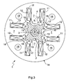
- Fig. 2 shows Fig. 2 the second end position, in which all second armature surfaces 6 rest against the second pole faces 9.
- the actuator 1 is also equipped with a return device 10.
- This restoring device 10 is designed so that it drives the armature 2 by means of restoring force in an initial position.
- This starting position is in Fig. 3 reproduced and lies between the two end positions.
- the restoring device 10 may comprise one or more springs and is designed such that it opposes a deflection of the armature 2 from the starting position in one direction and in an opposite opposite direction respectively resilient restoring forces, ie in particular spring forces. If there are no other forces acting on the armature 2, the starting position thus becomes self-evident, so that it can also be referred to as a neutral position.
- the return device 10 may be formed by a torsion spring, which is arranged coaxially in the present example in the interior of the shaft 3, which is designed for this purpose as a hollow shaft.
- the armature 2 can be held or fixed counter to the restoring force of the restoring device 10 with the aid of electromagnetic forces.
- a holding device 11 is provided which has at least a plurality of electromagnetic coils 12 and a The holding device 11 can generate the necessary electromagnetic forces by means of the coils 12, with which the armature 2 against the restoring force of the return device 10 can be held in its end positions.
- the actuator 1 preferably has four coils 12.
- the number of pole elements 7 is at least two and is straight. So basically two or six or eight pole elements 7 with the same number of coils 12 are possible.
- the pole elements 7 are arranged radially with respect to the axis of rotation 4.
- the coils 12 respectively coaxially surround the associated pole element 7, so that a winding axis of the respective coil 12 also extends radially.
- the holding device 11 is designed according to the invention so that, in the event that the armature 2 is to be fixed in one of its end positions, the coils 12 are energized so that the pole faces 8, 9 of adjacent pole elements 7 are magnetically polarized in opposite directions. In the case of the circumferentially adjacent pole elements 7, thus plus pole and minus pole alternate.
- the comparatively large number of coils 12 and pole elements 7, which are present for generating the electromagnetic forces required for holding the armature 2 makes it possible for the individual coils 12 To be supplied electric currents to keep relatively small. On the one hand, this results in relatively little heat being generated within the individual coils 12.
- the alternating in the circumferential direction polarity of the pole elements 7 favors in the end positions of the armature 2, the formation of a magnetic circuit or magnetic circuit that connects adjacent pole elements 7 via the armature 2 together. With the help of such a magnetic closure particularly high holding forces can be generated, at the same time the required power requirements decreases.
- the anchor surfaces 5, 6 and the pole faces 8, 9 are comparatively large and / or designed such that a planar contact between pole faces 8, 9 and anchor faces 5, 6 is formed in the respective end position.
- the holding device 11 may also be configured so that it energizes the coils 12 for fixing the armature 2 in its end positions in each of the two end positions with a constant electrical polarity. That is, for generating the holding forces in one end position and for generating the holding forces in the other end position, the coils 12 are not reversed, but only briefly turned off, unipolar operation, so that the armature 2 driven by the restoring force of the return device 10 from the Move out each end position and can accelerate towards the other end position. Since polarity reversal of the coils 12 is not required, the electromagnetic fields required to generate the required holding forces can be built up particularly quickly. At the same time this simplifies the power electronics. Since the electrical polarity of the coils 12 is equal in both end positions, resulting in these end positions and the same magnetic poles on the pole elements 7, which the Fig. 1 and 2 is removable.
- the armature 2 is designed asymmetrically, in such a way that in an initial state with in the starting position according to Fig. 3 resting armature 2 an energization of the coil 12 generates electromagnetic forces that attract the armature 2 in the direction of the one end position stronger than in the opposite direction to the other end position.
- This is achieved here in each case by a characteristic influencing 13, which increases the one end position associated anchor surface.
- the characteristic influencing 13 increases or the distance between the armature surfaces 5, 6 and the pole faces 8, 9 is changed asymmetrically in the starting position.
- Such a configuration makes it possible to excite the resting in the starting position armature 2 by a targeted energization of the coils 12 to vibrations, to reinforce them in the resonance range so far that the armature 2 can be collected in one of its end positions.
- the starting position of the armature 2 can be arranged asymmetrically between the two end positions.
- the first pole faces 8 and the first anchor faces 5 are associated with the first end position of the anchor 2, in which they rest against one another.
- all pole elements 7 are formed on a common yoke body 14.
- a magnetic yoke circuit can be closed, which additionally reinforces the insertion forces that can be introduced into the armature 2, with simultaneously reduced coil currents.
- the yoke body 14 may be appropriate as here be rotationally symmetrical with respect to the axis of rotation 4 and in particular have a circular outer periphery.
- the yoke body 14 is composed of several layers of a soft magnetic sheet or composite material.
- the yoke body 14 may be provided as here with a plurality of mounting holes 15, by means of which the yoke body 14 can be attached to another component.
- the armature 2 is arranged in an armature space 16, which is here in the yoke body 14, in particular centrally formed. Furthermore, each coil 12 is arranged in a coil space 17. Each coil space 17 is open to the armature space 16 and coaxially surrounds the respective pole element 7. The coil spaces 17 are likewise formed here in the yoke body 14. The dimensions of the coils 12 and the armature space 16 and the open sides of the coil spaces 17 are matched to one another in the preferred embodiment shown here, that the individual coils 12 are inserted into the respective coil space 17 in a fully wound state by the armature space 16, wherein the armature 2 is removed for this assembly process. This special dimensioning is of particular importance for a standard assembly of the actuator 1.
- the coils 12 can be wound and finished as part of a pre-assembly, so that the yoke body 14 can be fitted with the finished coil 12.
- the respective coil 12 is inserted axially into the armature space 16 and then transferred radially into the respective coil space 17.
- the pole elements 7 protrude only so far into the armature space 16 that the coils 12 are still readily insertable into the armature space 16.
- the armature 2 is provided with several, here with four wings 18, which extend axially along the armature 2 and project radially therefrom with respect to the axis of rotation 4.
- Each wing 18 carries one of the first anchor surfaces 5 and one of the second anchor surfaces 6.
- the number of wings 18 coincides with the number of pole elements 7, as well as their arrangement. Accordingly, the wings 18 are preferably arranged distributed uniformly in the circumferential direction.
- Each vane 18 merges into the characteristic influencing 13 at the side assigned to the first armature surface 5 in order to produce the asymmetry of the armature 2 described above.
Description
Die vorliegende Erfindung betrifft einen elektromagnetischen Stellantrieb zum Verstellen eines Stellglieds zwischen wenigstens drei Stellungen, mit den Merkmalen des Oberbegriffs des Anspruchs 1.The present invention relates to an electromagnetic actuator for adjusting an actuator between at least three positions, with the features of the preamble of
Stellantriebe dieser Art können beispielsweise zur Betätigung eines Lufttaktventils im Ansaugtrakt einer Brennkraftmaschine verwendet werden, mit dessen Hilfe eine Impulsaufladung der Brennkraftmaschine erzielt werden kann. Grundsätzlich sind auch andere Anwendungsformen möglich, bei denen ein Stellglied vorzugsweise innerhalb sehr kurzer Schaltzeiten zwischen zwei verschiedenen Schaltstellungen umgeschaltet werden muss. Beispielsweise ist eine Verwendung eines derartigen Stellantriebs zum Verstellen von Gaswechselventilen bei Kolbenmotoren denkbar.Actuators of this type can be used, for example, to actuate an air cycle valve in the intake of an internal combustion engine, with the help of a pulse charging the engine can be achieved. In principle, other forms of application are possible in which an actuator preferably has to be switched within very short switching times between two different switching positions. For example, a use of such an actuator for adjusting gas exchange valves in piston engines is conceivable.
Aus der
Beim bekannten Stellantrieb ist sämtlichen Polelementen eine gemeinsame elektromagnetische Spule zugeordnet, mit deren Hilfe die zum Festlegen des Ankers in dessen Endstellungen erforderlichen elektromagnetischen Kräfte erzeugt werden können. Durch die Verwendung nur einer einzigen Spule baut der bekannte Stellantrieb vergleichsweise kompakt und preiswert.In the known actuator all pole elements is associated with a common electromagnetic coil, by means of which the required for fixing the armature in its end positions electromagnetic forces can be generated. By using only a single coil of the known actuator builds comparatively compact and inexpensive.
Die vorliegende Erfindung beschäftigt sich mit dem Problem, für einen derartigen Stellantrieb eine verbesserte oder zumindest eine andere Ausführungsform anzugeben, die sich insbesondere durch eine vereinfachte und vorzugsweise preiswerte Herstellbarkeit auszeichnet.The present invention is concerned with the problem of providing for such an actuator improved or at least another embodiment, which is characterized in particular by a simplified and preferably inexpensive manufacturability.
Dieses Problem wird erfindungsgemäß durch den Gegenstand des unabhängigen Anspruchs gelöst. Vorteilhafte Ausführungsformen sind Gegenstand der abhängigen Ansprüche.This problem is solved according to the invention by the subject matter of the independent claim. Advantageous embodiments are the subject of the dependent claims.
Die Erfindung beruht auf dem allgemeinen Gedanken, die zum Festhalten des Ankers in dessen Endstellungen erforderlichen elektromagnetischen Kräfte mittels mehrerer Spulen zu erzeugen, wobei benachbarte Spulen zur Erzeugung dieser Kräfte gegensinnig gepolt werden. Auf diese Weise ist es möglich, sämtliche Spulen an der Erzeugung der elektromagnetischen Kräfte zum Festlegen des Ankers in der jeweiligen Endstellung zu beteiligen. Die Erfindung nutzt dabei die Erkenntnis, dass eine einzige Spule zur Erzeugung der erforderlichen elektromagnetischen Kräfte mit vergleichsweise hohen Strömen beaufschlagt werden muss, was einerseits höhere Verluste und eine relativ starke Wärmeentwicklung nach sich zieht. Andererseits ist zum Steuern der großen Ströme eine entsprechend aufwändige Leistungselektronik erforderlich. Eine derartige Leistungselektronik ist ihrerseits vergleichsweise teuer, verbraucht selbst vergleichsweise viel Energie und erzeugt entsprechend viel Abwärme. Im Unterschied dazu können die erforderlichen elektromagnetischen Kräfte mit mehreren Spulen bei deutlich geringeren Strömen innerhalb der einzelnen Spulen realisiert werden, wodurch sich die Verluste und die Wärmeentwicklung verringern. Von besonderer Bedeutung ist jedoch, dass die zum Schalten bzw. Steuern bzw. Regeln der Spulen erforderliche Elektronik nur noch vergleichsweise geringe Strömen schalten muss, so dass sie entsprechend einfach und preiswert realisiert werden kann und dabei einen vergleichsweise geringen eigenen Strombedarf aufweist und eine entsprechend geringe Wärmeentwicklung zeigt. Obwohl der erfindungsgemäße Stellantrieb mehrere Spulen benötigt, kann er aufgrund der aufgezeigten Vorteile am Ende preiswerter realisiert werden als der bekannte Stellantrieb, der nur eine einzige Spule aufweist.The invention is based on the general idea of producing the electromagnetic forces required for holding the armature in its end positions by means of a plurality of coils, wherein adjacent coils are polarized in opposite directions to generate these forces. In this way it is possible to involve all coils in the generation of the electromagnetic forces for fixing the armature in the respective end position. The invention makes use of the knowledge that a single coil for generating the required electromagnetic forces must be subjected to comparatively high currents, which on the one hand entails higher losses and a relatively strong generation of heat. On the other hand, a correspondingly complex power electronics is required to control the large currents. Such power electronics in turn is comparatively expensive, consumes even comparatively much energy and generates correspondingly much waste heat. In contrast, the required electromagnetic forces with multiple coils can be realized at significantly lower currents within the individual coils, thereby reducing losses and heat generation. Of particular importance, however, is that the electronics required for switching or controlling the coils only have to switch comparatively small currents, so that they can be realized correspondingly simply and inexpensively, while having a comparatively low own power requirement and a correspondingly low Heat development shows. Although the actuator according to the invention requires multiple coils, it can be realized at a lower cost due to the advantages shown at the end than the known actuator, which has only a single coil.
Bei einer vorteilhaften Ausführungsform sind die Polelemente und der Anker so aufeinander abgestimmt, dass sich in jeder Endstellung des Ankers ein geschlossener Magnetkreis ausbildet, der benachbarte Polelemente über den Anker miteinander verbindet. Mit Hilfe des über den Anker realisierten magnetischen Schlusses können in den Endstellungen extrem hohe Haltekräfte mit vergleichsweise niedrigen Strömen realisiert werden. Dies ist insbesondere im Hinblick auf die Wärmeentwicklung vorteilhaft.In an advantageous embodiment, the pole elements and the armature are coordinated so that forms a closed magnetic circuit in each end position of the armature, which connects adjacent pole elements via the armature with each other. Extremely high holding forces with comparatively low currents can be realized in the end positions with the aid of the magnetic closure realized via the armature. This is particularly advantageous in terms of heat generation.
Bei einer anderen Ausführungsform bestromt die Halteeinrichtung in beiden Endstellungen des Ankers die Spulen zum Festlegen des Ankers mit gleichbleibender Polung. Das bedeutet, dass zum Umschalten des Ankers zwischen den beiden Endstellungen die Bestromung der Spulen zwar (kurzzeitig) ausgeschaltet wird, damit der Anker von den der einen Endstellung zugeordneten Polflächen abheben kann, jedoch werden die Spulen zum Erzeugen der Haltekraft an den der anderen Endstellung zugeordneten Polflächen nicht umgepolt, sondern bei gleicher Polung lediglich wieder neu bestromt. Auf diese Weise kann die in den Spulen beim Ausschalten verbleibende Energie genutzt werden. Die erforderlichen elektromagnetischen Kräfte können auf diese Weise schneller erzeugt werden. Gleichzeitig sinkt der Strom- bzw. Energiebedarf des Stellantriebs. Darüber hinaus vereinfacht sich die Elektronik zum Steuern bzw. Regeln der Spulenbestromung.In another embodiment, the holding device in both end positions of the armature energizes the coils for fixing the armature with a constant polarity. This means that the switching of the armature between the two end positions, the energization of the coils (short-term) is turned off, so that the armature of the one end position associated pole faces can lift, but the coils are assigned to generate the holding force to the other end position Pole surfaces not reversed, but only re-energized with the same polarity. In this way, the energy remaining in the coils when switched off can be used. The required electromagnetic forces can be generated faster in this way. At the same time, the power or energy requirement of the actuator decreases. In addition, the electronics simplify controlling or regulating the coil energization.
Eine andere wichtige Ausführungsform charakterisiert sich dadurch, dass der Anker in einem Ankerraum angeordnet ist und die Spulen jeweils in einem zum Ankerraum offenen Spulenraum angeordnet sind. Des Weiteren sind die Spulen und der Ankerraum so aufeinander abgestimmt, dass die Spulen in einem fertig gewickelten Zustand bei entferntem Anker in den Ankerraum und von diesem in den jeweiligen Spulenraum einführbar sind. Diese Bauweise hat den großen Vorteil, dass die einzelnen Spulen im Rahmen einer Vormontage komplett gewickelt und fertiggestellt werden können, so dass im Rahmen einer Endmontage nur noch die fertigen Spulen in die Spulenräume eingesetzt werden müssen. Im Vergleich zu einer herkömmlichen Bauweise, bei der die jeweiligen Spulen unmittelbar am Polelement gewickelt werden müssen, bedeutet dies eine erhebliche Vereinfachung. Dementsprechend lässt sich der erfindungsgemäße Stellantrieb besonders preiswert herstellen.Another important embodiment is characterized in that the armature is arranged in an armature space and the coils are each arranged in a coil space open to the armature space. Furthermore, the coils and the armature space are matched to one another in such a way that the coils can be inserted into the armature space in a finished wound state with the armature removed and from there into the respective coil space. This design has the great advantage that the individual coils can be completely wound and finished in the course of a pre-assembly, so that in a final assembly only the finished coils must be inserted into the coil spaces. Compared to a conventional construction, in which the respective coils must be wound directly on the pole element, this means a considerable simplification. Accordingly, the actuator according to the invention can be produced particularly inexpensively.
Weitere wichtige Merkmale und Vorteile der Erfindung ergeben sich aus den Unteransprüchen, aus den Zeichnungen und aus der zugehörigen Figurenbeschreibung anhand der Zeichnungen.Other important features and advantages of the invention will become apparent from the dependent claims, from the drawings and from the associated figure description with reference to the drawings.
Es versteht sich, dass die vorstehend genannten und die nachstehend noch zu erläuternden Merkmale nicht nur in der jeweils angegebenen Kombination, sondern auch in anderen Kombinationen oder in Alleinstellung verwendbar sind, ohne den Rahmen der vorliegenden Erfindung zu verlassen.It is understood that the features mentioned above and those yet to be explained below can be used not only in the particular combination given, but also in other combinations or in isolation, without departing from the scope of the present invention.
Bevorzugte Ausführungsbeispiele der Erfindung sind in den Zeichnungen dargestellt und werden in der nachfolgenden Beschreibung näher erläutert, wobei sich gleiche Bezugszeichen auf gleiche oder ähnliche oder funktional gleiche Bauteile beziehen.Preferred embodiments of the invention are illustrated in the drawings and will be explained in more detail in the following description, wherein like reference numerals refer to the same or similar or functionally identical components.
Es zeigen, jeweils schematisch,
- Fig. 1 bis 3
- jeweils einen stark vereinfachten, prinzipiellen Querschnitt durch einen erfindungsgemäßen Stellantrieb bei unterschiedlichen Ankerstellungen.
- Fig. 1 to 3
- in each case a greatly simplified, fundamental cross section through an actuator according to the invention with different armature positions.
Entsprechend den
Der Stellantrieb 1 zeichnet sich insbesondere durch extrem kurze Schaltzeiten aus. Beispielsweise kann das Stellglied ein Ventil oder eine Klappe oder ein beliebiges anderes Stellorgan sein, das mit vergleichsweise hoher Geschwindigkeit bzw. mit extrem kurzen Schaltzeiten zwischen wenigstens zwei Schaltstellungen umgeschaltet werden soll. Vorzugsweise handelt es sich beim Stellantrieb 1 um einen Hochgeschwindigkeitsstellantrieb zur Betätigung eines Lufttaktventils, das in einem Ansaugtrakt angeordnet ist. Das Lufttaktventil ist dann das vom Stellantrieb 1 zum Verstellen angetriebene Stellglied. Ein derartiger Hochgeschwindigkeitsstellantrieb ist beispielsweise auch aus der
Ebenso ist eine andere Ausführungsform möglich, bei welcher der Stellantrieb 1 z. B. bei einem elektromagnetischen Ventiltrieb zum Verstellen eines Gaswechselventils einer Brennkraftmaschine zur Anwendung kommt. Die genannten Anwendungsbeispiele sind rein exemplarisch und ohne Beschränkung der Allgemeinheit.Likewise, another embodiment is possible in which the actuator 1 z. B. in an electromagnetic valve drive for adjusting a gas exchange valve of an internal combustion engine is used. The application examples mentioned are purely exemplary and without restriction of the general public.
Der Anker 2 weist mehrere Ankerflächen 5 und 6 auf. Im gezeigten, bevorzugten Ausführungsbeispiel sind insgesamt acht Ankerflächen 5, 6 vorgesehen, und zwar vier erste Ankerflächen 5 und vier zweite Ankerflächen 6. Der Anker 2 besteht aus einem weichmagnetischen Werkstoff.The
Des Weiteren weist der Stellantrieb 1 mehrere Polelemente 7 auf, die ebenfalls aus einem weichmagnetischen Werkstoff bestehen. Bevorzugt wird dabei eine bezüglich der Drehachse 4 gleichmäßige umfangsmäßige Verteilung der Polelemente 7. Diese Polelemente 7 weisen mehrere Polflächen 8, 9 auf. Im gezeigten, bevorzugten Ausführungsbeispiel sind genau vier Polelemente 7 vorgesehen, die insgesamt acht Polflächen 8, 9 aufweisen, nämlich vier erste Polflächen 8 und vier zweite Polflächen 9. An besagten Polflächen 8, 9 kommen die Ankerflächen 5, 6 in zwei Endstellungen des Ankers 2 zur Anlage.Furthermore, the
Der Stellantrieb 1 ist außerdem mit einer Rückstelleinrichtung 10 ausgestattet. Diese Rückstelleinrichtung 10 ist so ausgestaltet, dass sie den Anker 2 mittels Rückstellkraft in eine Ausgangsstellung antreibt. Diese Ausgangsstellung ist in
In den Endstellungen kann der Anker 2 entgegen der Rückstellkraft der Rückstelleinrichtung 10 mit Hilfe von elektromagnetischen Kräften festgehalten bzw. festgelegt werden. Hierzu ist eine Halteeinrichtung 11 vorgesehen, die zumindest mehrere elektromagnetische Spulen 12 aufweist sowie eine hier nicht gezeigte Leistungselektronik zum Steuern bzw. Regeln der Spulen 12. Die Halteeinrichtung 11 kann mit Hilfe der Spulen 12 die erforderlichen elektromagnetischen Kräfte erzeugen, mit denen der Anker 2 entgegen der Rückstellkraft der Rückstelleinrichtung 10 in seinen Endstellungen festgehalten werden kann.In the end positions, the
Erfindungsgemäß sind ebenso viele Spulen 12 wie Polelemente 7 vorgesehen. Dementsprechend weist der Stellantrieb 1 vorzugsweise vier Spulen 12 auf. Erfindungsgemäß beträgt die Anzahl der Polelemente 7 zumindest zwei und ist gerade. Also sind grundsätzlich auch zwei oder sechs oder acht Polelemente 7 mit derselben Anzahl an Spulen 12 möglich.According to the invention, as
Die Polelemente 7 sind bezüglich der Drehachse 4 radial angeordnet. Die Spulen 12 umschließen jeweils koaxial das zugehörige Polelement 7, so dass eine Wickelachse der jeweiligen Spule 12 ebenfalls radial verläuft.The
Die Halteeinrichtung 11 ist erfindungsgemäß so ausgestaltet, dass sie für den Fall, dass der Anker 2 in einer seiner Endstellungen festgelegt werden soll, die Spulen 12 so bestromt, dass die Polflächen 8, 9 benachbarter Polelemente 7 gegensinnig magnetisch gepolt sind. Bei den in Umfangsrichtung benachbarten Polelementen 7 wechseln sich somit Plus-Pol und Minus-Pol ab. Die vergleichsweise große Anzahl an Spulen 12 und Polelementen 7, die zur Erzeugung der zum Halten des Ankers 2 benötigten elektromagnetischen Kräfte vorhanden sind, ermöglicht es, die den einzelnen Spulen 12 zuzuführenden elektrischen Ströme relativ klein zu halten. Dies führt einerseits dazu, dass innerhalb der einzelnen Spulen 12 nur relativ wenig Wärme erzeugt wird. Zum anderen ist zum Schalten der Spulen 12 nur eine vergleichsweise einfache Leistungselektronik erforderlich, die entsprechend preiswert realisierbar ist und ihrerseits einen vergleichsweise niedrigen Stromverbrauch mit entsprechend niedriger Wärmeentwicklung aufweist. Darüber hinaus werden am Anker 2 die elektromagnetischen Kräfte umfangsmäßig vergleichsweise gleichmäßig verteilt eingeleitet, wodurch auch hier Verluste vermieden werden können. Außerdem kann der Anker 2 in radialer Richtung vergleichsweise klein bauen, wodurch er ein entsprechend kleines Trägheitsmoment aufweist, was schnelle Schaltbetätigungen begünstigt.The holding
Die in Umfangsrichtung abwechselnde Polung der Polelemente 7 begünstigt in den Endstellungen des Ankers 2 die Ausbildung eines magnetischen Schlusses oder Magnetkreises, der benachbarte Polelemente 7 über den Anker 2 miteinander verbindet. Mit Hilfe eines derartigen magnetischen Schlusses können besonders hohe Haltekräfte erzeugt werden, wobei gleichzeitig der hierzu erforderliche Strombedarf sinkt.The alternating in the circumferential direction polarity of the
Um diesen magnetischen Schluss möglichst effektiv auszugestalten, sind die Ankerflächen 5, 6 und die Polflächen 8, 9 vergleichsweise groß und/oder so ausgestaltet, dass sich eine flächige Kontaktierung zwischen Polflächen 8, 9 und Ankerflächen 5, 6 in der jeweiligen Endstellung ausbildet.In order to design this magnetic closure as effectively as possible, the anchor surfaces 5, 6 and the pole faces 8, 9 are comparatively large and / or designed such that a planar contact between pole faces 8, 9 and anchor faces 5, 6 is formed in the respective end position.
Vorzugsweise kann die Halteeinrichtung 11 außerdem so ausgestaltet sein, dass sie die Spulen 12 zum Festlegen des Ankers 2 in dessen Endstellungen in jeder der beiden Endstellungen mit gleichbleibender elektrischer Polung bestromt. Das heißt, zum Erzeugen der Haltekräfte in der einen Endstellung und zum Erzeugen der Haltekräfte in der anderen Endstellung, werden die Spulen 12 nicht umgepolt, sonder lediglich kurzzeitig ausgeschaltet, unipolarer Betrieb, damit sich der Anker 2 angetrieben durch die Rückstellkraft der Rückstelleinrichtung 10 aus der jeweiligen Endstellung herausbewegen und in Richtung der anderen Endstellung beschleunigen kann. Da eine Umpolung der Spulen 12 nicht erforderlich ist, können die zum Erzeugen der benötigten Haltekräfte erforderlichen elektromagnetischen Felder besonders rasch aufgebaut werden. Gleichzeitig vereinfacht sich dadurch die Leistungselektronik. Da die elektrische Polung der Spulen 12 in beiden Endstellungen gleich ist, ergeben sich in diesen Endstellungen auch gleiche magnetische Pole an den Polelementen 7, was den
Bei der hier gezeigten Ausführungsform ist der Anker 2 unsymmetrisch ausgestaltet, und zwar so, dass bei einem Ausgangszustand mit in der Ausgangsstellung gemäß
Entsprechend
Vorzugsweise sind alle Polelemente 7 an einem gemeinsamen Jochkörper 14 ausgebildet. Auf diese Weise kann in den Endstellungen des Ankers 2 ein magnetischer Rückschlusskreis geschlossen werden, was zusätzlich die in den Anker 2 einleitbaren Haltekräfte verstärkt, bei gleichzeitig reduzierten Spulenströmen. Der Jochkörper 14 kann wie hier zweckmäßig bezüglich der Drehachse 4 rotationssymmetrisch ausgestaltet sein und insbesondere einen kreisförmigen Außenumfang aufweisen. Vorzugsweise ist der Jochkörper 14 aus mehreren Lagen eines weichmagnetischen Blechs oder auch aus Kompositmaterial aufgebaut. Außerdem kann der Jochkörper 14 wie hier mit mehreren Montageöffnungen 15 versehen sein, mit deren Hilfe der Jochkörper 14 an einem anderen Bauteil befestigt werden kann.Preferably, all
Der Anker 2 ist in einem Ankerraum 16 angeordnet, der hier im Jochkörper 14, insbesondere zentral, ausgebildet ist. Des weiteren ist jede Spule 12 in einem Spulenraum 17 angeordnet. Jeder Spulenraum 17 ist zum Ankerraum 16 hin offen und umschließt koaxial das jeweilige Polelement 7. Die Spulenräume 17 sind hier ebenfalls im Jochkörper 14 ausgebildet. Die Dimensionierungen der Spulen 12 und des Ankerraums 16 sowie der offenen Seiten der Spulenräume 17 sind bei der hier gezeigten, bevorzugten Ausführungsform so aufeinander abgestimmt, dass die einzelnen Spulen 12 in einem fertig gewickelten Zustand durch den Ankerraum 16 in den jeweiligen Spulenraum 17 einführbar sind, wobei der Anker 2 für diesen Montagevorgang entfernt ist. Diese spezielle Dimensionierung ist für eine serienmäßige Montage des Stellantriebs 1 von besonderer Bedeutung. Denn die Spulen 12 können im Rahmen einer Vormontage gewickelt und fertiggestellt werden, so dass der Jochkörper 14 mit den fertigen Spulen 12 bestückt werden kann. Hierzu wird die jeweilige Spule 12 axial in den Ankerraum 16 eingeführt und anschließend radial in den jeweiligen Spulenraum 17 überführt. Um dies zu ermöglichen, ragen beispielsweise die Polelemente 7 nur so weit in den Ankerraum 16 ein, dass die Spulen 12 noch ohne weiteres in den Ankerraum 16 einführbar sind.The
Zur Ausbildung der Ankerflächen 5, 6 am Anker 2 ist der Anker 2 mit mehreren, hier mit vier Flügeln 18 ausgestattet, die sich entlang des Ankers 2 axial erstrecken und von diesem bezüglich der Drehachse 4 radial abstehen. Jeder Flügel 18 trägt eine der ersten Ankerflächen 5 sowie eine der zweiten Ankerflächen 6. Die Anzahl der Flügel 18 stimmt mit der Anzahl der Polelemente 7 überein, ebenso wie deren Anordnung. Dementsprechend sind die Flügel 18 in Umfangsrichtung vorzugsweise gleichmäßig verteilt angeordnet. Jeder Flügel 18 geht an der der ersten Ankerfläche 5 zugeordneten Seite in die Kennlinienbeeinflussung 13 über, um die oben beschriebene Asymmetrie des Ankers 2 zu erzeugen.To form the anchor surfaces 5, 6 on the
Claims (10)
- An electromagnetic actuator drive for adjusting a final controlling element among at least three positions, comprising- a soft magnetic armature (2) which is drive-coupleable to the final controlling element and has a plurality of armature faces (5, 6),- a plurality of soft magnetic pole elements (7), each having a plurality of pole faces (8, 9) on which the armature faces (5, 6) come to rest in two end positions of the armature (2),- a restoring device (10) which drives the armature (2) by means of a restoring force into a starting position between the end positions,- a holding device (11) with the help of which the armature (2) can be secured in its end positions by means of electromagnetic forces, characterized in that- the holding device (11) comprises several electromagnetic coils (12) and electronic power equipment for controlling and/or regulating the coils (12),- an even number of at least two pole elements (7) is provided,- a separate electromagnetic coil (12) is assigned to each pole element (7),- the hold device (11) applies electric current to the coils (12) for securing the armature (2) in its end positions so that the pole faces (8, 9) of neighboring pole elements (7) are oppositely polarized.
- The actuator drive according to Claim 1, characterized in that
a magnetic circuit is formed in each end position, connecting each pole element (7) to the neighboring pole elements (7) across the armature (2). - The actuator drive according to Claim 1 or 2, characterized in that
the holding device (11) applies electricity of uniform polarity to the coils (12) in both end positions of the armature (2) to secure the armature (2). - The actuator drive according to any one of Claims 1 through 3,
characterized in that- the armature (2) is mounted to be adjustable between its end positions rotatably about an axis of rotation (4),- wherein preferably with regard to the axis of rotation (4) the pole elements (7) are distributed around the circumference and/or are aligned radially. - The actuator drive according to any one of Claims 1 through 4,
characterized in that
exactly four pole elements (7) and exactly four coils (12) are provided. - The actuator drive according to any one of Claims 1 through 5,
characterized in that- the pole elements (7) arranged asymmetrically or designed to be asymmetrical so that the armature (2) which is resting in its starting position is attracted more strongly when the electricity applied to the coils (12) is acting in the direction of the one end position than in the opposite direction, and/or- the armature (2) is designed to be asymmetrical so that the armature (2) which is stationary in its starting position is attracted more strongly when the electricity applied to the coils (12) is acting in the direction of the one end position than in the opposite direction, and/or- the starting position is arranged asymmetrically between the end positions so that the armature (2) which is stationary in its starting position is pulled more strongly when current is applied to the coils (12) in the direction of the one end position than in the opposite direction. - The actuator drive according to any one of Claims 1 through 6,
characterized in that
each pole element (7) has two pole faces (8, 9) each being assigned to one of the end positions of the armature (2). - The actuator drive according to any one of Claims 1 through 7,
characterized in that- all the pole elements (7) are formed on a common yoke body (14),- wherein preferably the yoke body (14) is designed to be rotationally symmetrical with regard to an axis of rotation of the armature (2) and/or is constructed from multiple layers of a soft magnetic sheet metal or a composite material. - The actuator drive according to any one of Claims 1 through 8,
characterized in that- the armature (2) is arranged in an armature space (16),- each coil (12) is arranged in a coil space (17) that is open toward the armature space (16),- the coils (12) and the armature space (16) are coordinated with one another so that the coils (12) in a completely wound state can be inserted into the armature space (16) when the armature (2) is not present and can be inserted from this space into the respective coil space (17). - The actuator drive according to any one of Claims 1 through 9,
characterized in that- the armature (2) has a wing (18) for each pole element (7), said wing protruding radially with respect to an axis of rotation (4) of the armature (2), and/or- wherein preferably the wings (18) each have two armature faces (5, 6) each being assigned to one of the end positions of the armature (2) and/or are distributed around the circumference with regard to the axis of rotation (4).
Applications Claiming Priority (2)
| Application Number | Priority Date | Filing Date | Title |
|---|---|---|---|
| DE200510026535 DE102005026535A1 (en) | 2005-06-08 | 2005-06-08 | Electromagnetic actuator drive for e.g. actuating air valve in intake tract of engine, has holding device that applies current to coils and secures armature in its end positions so that faces of neighboring poles are oppositely polarized |
| DE200510029018 DE102005029018A1 (en) | 2005-06-21 | 2005-06-21 | Electromagnetic actuator drive for e.g. actuating air valve in intake tract of engine, has holding device that applies current to coils and secures armature in its end positions so that faces of neighboring poles are oppositely polarized |
Publications (3)
| Publication Number | Publication Date |
|---|---|
| EP1732088A2 EP1732088A2 (en) | 2006-12-13 |
| EP1732088A3 EP1732088A3 (en) | 2007-10-31 |
| EP1732088B1 true EP1732088B1 (en) | 2013-08-14 |
Family
ID=36939120
Family Applications (1)
| Application Number | Title | Priority Date | Filing Date |
|---|---|---|---|
| EP06113990.3A Expired - Fee Related EP1732088B1 (en) | 2005-06-08 | 2006-05-16 | Electromagnetic actuator |
Country Status (2)
| Country | Link |
|---|---|
| US (1) | US7623012B2 (en) |
| EP (1) | EP1732088B1 (en) |
Families Citing this family (5)
| Publication number | Priority date | Publication date | Assignee | Title |
|---|---|---|---|---|
| EP2189993B1 (en) * | 2008-11-21 | 2018-05-30 | Mahle International GmbH | Actuation device, valve means and operating method |
| DE102008058525A1 (en) * | 2008-11-21 | 2010-05-27 | Mahle International Gmbh | Actuating device, valve device and operating method |
| WO2011022554A1 (en) * | 2009-08-19 | 2011-02-24 | Raymond James Walsh | Radial solenoid array |
| JP6490150B2 (en) * | 2017-06-16 | 2019-03-27 | ファナック株式会社 | Reactor with iron core and coil |
| GB2585835B (en) * | 2019-07-16 | 2023-07-19 | Eaton Intelligent Power Ltd | Relay |
Family Cites Families (12)
| Publication number | Priority date | Publication date | Assignee | Title |
|---|---|---|---|---|
| US3970979A (en) * | 1975-07-02 | 1976-07-20 | General Scanning Inc. | Limited rotation motor with velocity sensing system |
| US4187452A (en) * | 1975-08-27 | 1980-02-05 | International Business Machines Corporation | Electromechanical torsional oscillator with resonant frequency and amplitude control |
| US4329672A (en) * | 1977-01-29 | 1982-05-11 | Elektro-Mechanik Gmbh | Polarized electromagnetic drive for a limited operating range of a control element |
| GB2120463B (en) | 1982-05-13 | 1985-12-11 | Racal Mesl Microwave | Improvements in and relating to rotary actuators |
| US4899073A (en) * | 1987-07-24 | 1990-02-06 | Nippondenso Co., Ltd. | 3-position rotational actuator |
| US4845424A (en) * | 1987-11-16 | 1989-07-04 | Gamble John G | Rotary displacement motor |
| SE9503688L (en) * | 1995-10-20 | 1997-04-21 | Asea Brown Boveri | Electromagnetic actuator |
| DE19739068A1 (en) * | 1997-09-08 | 1999-03-25 | Philips Patentverwaltung | Electromotive adjustment drive |
| FR2793944B1 (en) * | 1999-05-20 | 2001-07-13 | Schneider Electric Ind Sa | OPENING AND / OR CLOSING CONTROL DEVICE, PARTICULARLY FOR A BREAKING APPARATUS SUCH AS A CIRCUIT BREAKER, AND CIRCUIT BREAKER PROVIDED WITH SUCH A DEVICE |
| GB0014947D0 (en) | 2000-06-16 | 2000-08-09 | Glaxo Group Ltd | Novel pharmaceutical formulation |
| FR2834119B1 (en) * | 2001-08-30 | 2004-05-21 | Moving Magnet Tech Mmt | ELECTROMAGNETIC ACTUATOR WITH TWO STABLE LIMIT POSITIONS, IN PARTICULAR FOR CONTROLLING AIR INLET DUCT VALVES FOR INTERNAL COMBUSTION ENGINES |
| DE102004037360B4 (en) | 2003-07-31 | 2018-02-15 | Mahle Filtersysteme Gmbh | Electromagnetic actuator |
-
2006
- 2006-05-16 EP EP06113990.3A patent/EP1732088B1/en not_active Expired - Fee Related
- 2006-05-31 US US11/444,098 patent/US7623012B2/en not_active Expired - Fee Related
Also Published As
| Publication number | Publication date |
|---|---|
| US7623012B2 (en) | 2009-11-24 |
| EP1732088A2 (en) | 2006-12-13 |
| EP1732088A3 (en) | 2007-10-31 |
| US20060279389A1 (en) | 2006-12-14 |
Similar Documents
| Publication | Publication Date | Title |
|---|---|---|
| EP2686894A1 (en) | Actuator | |
| DE102006033174A1 (en) | Coil arrangement with a coil carrier of an electromagnetic drive | |
| EP1732088B1 (en) | Electromagnetic actuator | |
| DE102009015486A1 (en) | Electromagnetic actuator comprises housing with electrically energized magnetic coil device, and magnetic coil device generates magnetic field, where stationary core area is commonly assigned to permanent magnets | |
| DE102009014304A1 (en) | actuator | |
| EP2929550B1 (en) | Electromagnetic actuating apparatus | |
| EP3191695A1 (en) | Electromagnetic regulating device | |
| DE102012107922A1 (en) | Electromagnetic actuator device | |
| DE102011014192A1 (en) | Electromagnetic actuating device, has coil unit activated by energization of magnetic flux shift i.e. magnetic flux displacement, of permanent magnetic fluxes from yoke section to another yoke section | |
| DE602004007420T2 (en) | Electromagnetic actuator for actuating a gas exchange valve on a reciprocating internal combustion engine and internal combustion engine with such an actuator | |
| DE102013202459A1 (en) | Halt brake for seating device, has magnetic coil whose magnetic flux is passed over profiles in currentless state, where reluctance force is generated by flux in circumferential direction of rotor and forms air gaps between profiles | |
| EP1869756B1 (en) | Linear actuator | |
| DE102005017482B4 (en) | Gas exchange valve actuator for a valve-controlled internal combustion engine | |
| WO2003018979A1 (en) | High-speed controlling device | |
| DE102006017233B4 (en) | Rotor arrangement for an electric machine and claw pole motor | |
| DE102005026535A1 (en) | Electromagnetic actuator drive for e.g. actuating air valve in intake tract of engine, has holding device that applies current to coils and secures armature in its end positions so that faces of neighboring poles are oppositely polarized | |
| DE102004037360B4 (en) | Electromagnetic actuator | |
| DE102004062340B4 (en) | Electromagnetic drive with flux guide pieces | |
| DE102005029018A1 (en) | Electromagnetic actuator drive for e.g. actuating air valve in intake tract of engine, has holding device that applies current to coils and secures armature in its end positions so that faces of neighboring poles are oppositely polarized | |
| DE102020104575A1 (en) | Electric motor with field reinforcement | |
| DE102019133035A1 (en) | ACTUATING DEVICE FOR ADJUSTING MECHANISM | |
| DE102013105670A1 (en) | Bistable electro-permanent actuator | |
| DE10045957B4 (en) | Electromagnetic linear actuator | |
| DE102011086149A1 (en) | Holder assembly for use in brushless motor for holding piston of automobile, has magnet radially surrounded by other magnet, where poles of latter magnet are arranged behind poles of former magnet in holding position along radial direction | |
| DE102016210975A1 (en) | Valve train for an internal combustion engine |
Legal Events
| Date | Code | Title | Description |
|---|---|---|---|
| PUAI | Public reference made under article 153(3) epc to a published international application that has entered the european phase |
Free format text: ORIGINAL CODE: 0009012 |
|
| AK | Designated contracting states |
Kind code of ref document: A2 Designated state(s): AT BE BG CH CY CZ DE DK EE ES FI FR GB GR HU IE IS IT LI LT LU LV MC NL PL PT RO SE SI SK TR |
|
| AX | Request for extension of the european patent |
Extension state: AL BA HR MK YU |
|
| PUAL | Search report despatched |
Free format text: ORIGINAL CODE: 0009013 |
|
| AK | Designated contracting states |
Kind code of ref document: A3 Designated state(s): AT BE BG CH CY CZ DE DK EE ES FI FR GB GR HU IE IS IT LI LT LU LV MC NL PL PT RO SE SI SK TR |
|
| AX | Request for extension of the european patent |
Extension state: AL BA HR MK YU |
|
| RIC1 | Information provided on ipc code assigned before grant |
Ipc: H01F 7/14 20060101AFI20060911BHEP Ipc: H01F 7/08 20060101ALI20070927BHEP Ipc: F01L 9/04 20060101ALI20070927BHEP |
|
| 17P | Request for examination filed |
Effective date: 20071128 |
|
| 17Q | First examination report despatched |
Effective date: 20080125 |
|
| AKX | Designation fees paid |
Designated state(s): DE FR GB |
|
| GRAP | Despatch of communication of intention to grant a patent |
Free format text: ORIGINAL CODE: EPIDOSNIGR1 |
|
| INTG | Intention to grant announced |
Effective date: 20130405 |
|
| GRAS | Grant fee paid |
Free format text: ORIGINAL CODE: EPIDOSNIGR3 |
|
| GRAA | (expected) grant |
Free format text: ORIGINAL CODE: 0009210 |
|
| AK | Designated contracting states |
Kind code of ref document: B1 Designated state(s): DE FR GB |
|
| REG | Reference to a national code |
Ref country code: GB Ref legal event code: FG4D Free format text: NOT ENGLISH |
|
| REG | Reference to a national code |
Ref country code: DE Ref legal event code: R096 Ref document number: 502006013108 Country of ref document: DE Effective date: 20131010 |
|
| PLBE | No opposition filed within time limit |
Free format text: ORIGINAL CODE: 0009261 |
|
| STAA | Information on the status of an ep patent application or granted ep patent |
Free format text: STATUS: NO OPPOSITION FILED WITHIN TIME LIMIT |
|
| 26N | No opposition filed |
Effective date: 20140515 |
|
| REG | Reference to a national code |
Ref country code: DE Ref legal event code: R097 Ref document number: 502006013108 Country of ref document: DE Effective date: 20140515 |
|
| REG | Reference to a national code |
Ref country code: FR Ref legal event code: PLFP Year of fee payment: 11 |
|
| REG | Reference to a national code |
Ref country code: DE Ref legal event code: R084 Ref document number: 502006013108 Country of ref document: DE |
|
| REG | Reference to a national code |
Ref country code: FR Ref legal event code: PLFP Year of fee payment: 12 |
|
| REG | Reference to a national code |
Ref country code: FR Ref legal event code: PLFP Year of fee payment: 13 |
|
| PGFP | Annual fee paid to national office [announced via postgrant information from national office to epo] |
Ref country code: FR Payment date: 20180529 Year of fee payment: 13 |
|
| PGFP | Annual fee paid to national office [announced via postgrant information from national office to epo] |
Ref country code: GB Payment date: 20180530 Year of fee payment: 13 Ref country code: DE Payment date: 20180731 Year of fee payment: 13 |
|
| REG | Reference to a national code |
Ref country code: DE Ref legal event code: R119 Ref document number: 502006013108 Country of ref document: DE |
|
| GBPC | Gb: european patent ceased through non-payment of renewal fee |
Effective date: 20190516 |
|
| PG25 | Lapsed in a contracting state [announced via postgrant information from national office to epo] |
Ref country code: DE Free format text: LAPSE BECAUSE OF NON-PAYMENT OF DUE FEES Effective date: 20191203 Ref country code: GB Free format text: LAPSE BECAUSE OF NON-PAYMENT OF DUE FEES Effective date: 20190516 |
|
| PG25 | Lapsed in a contracting state [announced via postgrant information from national office to epo] |
Ref country code: FR Free format text: LAPSE BECAUSE OF NON-PAYMENT OF DUE FEES Effective date: 20190531 |