EP0596570B1 - Vorrichtung zum Aufrauhen und Kleben von Schuhen - Google Patents
Vorrichtung zum Aufrauhen und Kleben von Schuhen Download PDFInfo
- Publication number
- EP0596570B1 EP0596570B1 EP93203047A EP93203047A EP0596570B1 EP 0596570 B1 EP0596570 B1 EP 0596570B1 EP 93203047 A EP93203047 A EP 93203047A EP 93203047 A EP93203047 A EP 93203047A EP 0596570 B1 EP0596570 B1 EP 0596570B1
- Authority
- EP
- European Patent Office
- Prior art keywords
- machine
- shoe
- supports
- support
- working
- Prior art date
- Legal status (The legal status is an assumption and is not a legal conclusion. Google has not performed a legal analysis and makes no representation as to the accuracy of the status listed.)
- Expired - Lifetime
Links
- 238000009960 carding Methods 0.000 claims description 20
- 238000005452 bending Methods 0.000 claims description 3
- 230000007480 spreading Effects 0.000 claims description 2
- 230000002093 peripheral effect Effects 0.000 claims 1
- 239000004568 cement Substances 0.000 description 3
- 238000007788 roughening Methods 0.000 description 3
- 230000008859 change Effects 0.000 description 2
- 230000007246 mechanism Effects 0.000 description 2
- 230000009471 action Effects 0.000 description 1
- 238000000034 method Methods 0.000 description 1
- 230000008569 process Effects 0.000 description 1
Images

Classifications
-
- A—HUMAN NECESSITIES
- A43—FOOTWEAR
- A43D—MACHINES, TOOLS, EQUIPMENT OR METHODS FOR MANUFACTURING OR REPAIRING FOOTWEAR
- A43D37/00—Machines for roughening soles or other shoe parts preparatory to gluing
-
- A—HUMAN NECESSITIES
- A43—FOOTWEAR
- A43D—MACHINES, TOOLS, EQUIPMENT OR METHODS FOR MANUFACTURING OR REPAIRING FOOTWEAR
- A43D111/00—Shoe machines with conveyors for jacked shoes or for shoes or shoe parts
-
- A—HUMAN NECESSITIES
- A43—FOOTWEAR
- A43D—MACHINES, TOOLS, EQUIPMENT OR METHODS FOR MANUFACTURING OR REPAIRING FOOTWEAR
- A43D25/00—Devices for gluing shoe parts
- A43D25/18—Devices for applying adhesives to shoe parts
Definitions
- the general object of the present invention is to obviate the above drawbacks by providing an automatic machine capable of carrying out both roughening and cementing operations, while at the same time optimizing the processing time by the simultaneous working of two shoes.
- a carding-cementing machine for shoes which comprises a pair of supports each supporting a shoe to be worked, a first and a second working head being disposed above said supports, the first working head comprising a carding tool and the second head comprising a cement-delivering tool, said supports and working heads being mutually movable so that the carding tool can travel over a predetermined path on the bottom of a shoe disposed on the first support while the cementing tool can cover a predetermined path on the bottom of a second shoe disposed on the second support, the mutual positions between the supports and the working heads being interchangeable with respect to each other so that the carding tool may be also capable of travelling over a predetermined path on the bottom of a shoe disposed on the second support, while the cementing tool can follow a predetermined path on the bottom of another shoe disposed on the first support.
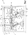
- a machine in accordance with the invention comprises a supporting frame 11 bearing two carriages 12, 13, each designed to receive a corresponding last or shoe to be made 14, 15 having its bottom turned upwardly.
- carriages 12, 13 are movable transversely of the machine extension along horizontal guide rails 16, 17.
- One working or carding head 18 and a second working or cementing head are present above the carriages 12, 13.
- the first working head 18 is movable horizontally in a direction longitudinal to the machine along guide rails 19 supported by a carriage 20 which in turn is vertically movable along guides 21 fastened to the frame 11.
- movement of the head 18 can take place by a lead-screw unit 22 operated by an electric motor 23, whereas the vertical movement of carriage 20 can take place by means of a second lead-screw unit 24 operated by an electric motor 25.
- the second working head 26 is on the contrary movable vertically along a vertical guide 27, in turn supported by a carriage 28 horizontally movable along guide rails 29 supported by the frame 11 and parallel to the guide rails 19.
- movement of the head 26 can take place by means of a lead-screw unit 30 operated by an electric motor 31, whereas the horizontal movement of carriage 28 can take place by means of a second lead-screw unit 32 operated by an electric motor 33.
- Carriages 12, 13 supporting the shoe are power driven to be movable along the respective guide rails 16, 17 between a receded position and an advanced position which are located to the farthest right and left ends respectively, as viewed looking Fig. 2.
- Means for actuating carriages 12, 13, not shown for the sake of simplicity, can consist of power driven screw-lead units, as described above with reference to the working head.
- shoes can be alternately brought to intersect the vertical planes parallel to each other in which the first or second head moves.
- the support carriages 12, 13 are identical with each other and comprise a base 34, 35 slidable on respective guide rails 16, 17.
- Each base 34, 35 carries a fixed rear support and a movable front support for the shoe. Also located on the base is a central reclining support.
- the rear supporting portion 38 comprises two grippers 39 for laterally tightening the shoe heel area.
- the central support portion comprises a post 36 adjustable in height, on top of which the shoe last carrying the shoe is fitted, said post being pivotally mounted at the rear part thereof according to an axis 41 enabling it to be tilted forward by means of an actuator 42, thereby moving from the upright position drawn in solid line in the figure to the inclined position drawn in chain line.
- the front support portion 43 comprises a slide 44 horizontally movable along guide rails 45 parallel to the shoe extension.
- the slide movement can be obtained by power driven screw-lead units not shown in the drawing for the sake of clarity.
- Grippers 40 are disposed on the slide 44 for laterally tightening the toe portion of the shoe, and also provided is a locking device 46 for the shoe toe.
- the device 46 comprises an actuator 47 designed to move it vertically.
- the slide 44 moves forward to the position in chain line and the central support is tilted forward for facilitating fitting (this is particularly useful in case of boots). After the shoe has been positioned on the central support 36, the latter goes back to the upright position, the slide 44 moves back towards the shoe and grippers 39 and 40 are tightened. The locking device 46 rises and entraps the shoe toe, which is therefore perfectly fixed.
- the toe locking device ensures the exact positioning of the shoe relative to the working heads.
- the head 18 comprises a rotating carding brush 54 movable along the periphery of the shoe bottom.
- Said carding head 18 being the object of an Italian patent application No.MI91A000950 in the name of the same Applicant, will not be described in detail but only enough to enable comprehension of the present invention
- the head 18 comprises a slide 48 for movement along the guide rails 19.
- Fastened to the slide 48 is a sleeve 49 for rotation of an arm 50 about a vertical axis 51 by means of actuators 52.
- the arm 50 carries a second arm 53 supporting the power driven carding rotating brush 54.
- the arm 53 is movable in the brush plane to enable said brush to rest on the shoe bottom while exerting a predetermined pressure.
- the arm 53 may also be rotated by an actuating means 55 to enable tilting of the brush plane about a tangency line of the brush to the shoe, so that the brush can be kept tangent to the shoe bottom while the tool is being moved.
- the axis 51 substantially passes through the contact point of the brush with the shoe bottom so that upon operation of actuators 52, the brush plane rotates through 180° about this contact point.
- the brush while rotating always in the same direction, has a rotatory movement at the tangency point with the shoe bottom which is always directed towards the inside of said bottom over the whole travel of the head along the shoe perimeter.
- the cementing machine 26 comprises on the contrary a nozzle 56 dispensing cement in a controlled manner.
- a nozzle 56 is surrounded by a spreading brush 57 rotatably moved about the nozzle axis by a motor 58 so that cement can be uniformly distributed.
- the nozzle is supported by a kinematic mechanism for its controlled tilting according to planes transverse and longitudinal to the shoe, so that the nozzle can be maintained always perpendicular to the shoe bottom while it is moving for carrying out the cementing operation.
- the cementing head 26 comprises a slide 59 slidable along a vertical guide 27.
- a first arched guide 60 extending in a plane transverse to the machine.
- Slidable on the arched guide 60 is a carriage 61 moved by an actuator 62 and supporting a second arched guide 63 extending in a plane longitudinal to the machine.
- Slidable on said second arched guide 63 is a carriage 64 driven by an actuator 65 and supporting the delivery nozzle 56.
- the bending centres of the arched guides are adapted to identify a rotation centre coinciding with the nozzle delivery end. In this manner, by moving the carriages on said guides, the nozzle tilts while at the same time keeping its outlet end fixed.
- control device 66 substantially of known type and therefore not shown in detail as it can be easily envisaged by a person skilled in the art.
- a control device may be embodied by an electronic microprocessor circuit suitably programmed, as will be apparent from the following description concerning operation.
- the brush will travel over one shoe edge and will then rotate through 180° so as to follow the opposite shoe edge.
- the device 47 Upon the brush passing close to the shoe toe, the device 47 will retract the locking device 46, in order to let the brush freely pass, said locking device being immediately afterwards positioned in place again.
- the carding head When work is over, the carding head will park in a position at which it does not interfere with the shoe and the work heads change of place relative to each other sliding along the respective horizontal guide rails.
- the cement-delivering nozzle By its own movement and the corresponding movement of carriage 12, the cement-delivering nozzle can therefore travel over its path along the shoe bottom as established, while keeping its outlet opening always tangent thereto.
- the actuators may be embodied either by electric, or pneumatic or hydraulic elements.
- the carding head may also be a traditional head provided with two rotating brushes, disposed on either side of the shoe to be processed.
Landscapes
- Preliminary Treatment Of Fibers (AREA)
- Treatment Of Fiber Materials (AREA)
Claims (16)
- Eine Aufrauh/Klebe-Maschine für Schuhe mit: einem ersten und einem zweiten Träger (12,13), die jeweils einen zu bearbeitenden Schuh (14, 15) tragen; einem ersten und einem zweiten Arbeitskopf (18, 26), die oberhalb der Träger (12, 13) angeordnet und in vertikalen Ebenen parallel zueinander beweglich sind, wobei der erste Arbeitskopf (18) ein Aufrauh-Werkzeug (54) und der zweite Arbeitskopf (26) ein einen Klebstoff zuführendes Werkzeug (56) aufweist; und die Arbeitsköpfe antreibenden Mitteln (23, 25; 31, 33) und die Träger antreibende Mittel, die derart zusammenwirken, daß:- die Arbeitsköpfe (18, 26) entlang vorgegebener Wege an den Sohlen der Schuhe (14, 15), die an den Trägern (12, 13) angeordnet sind, positioniert werden; und- die gegenseitigen Positionen der Träger (12, 13) und der Arbeitsköpfe (18, 26) zwischen einer ersten Arbeitsposition, in der der erste und der zweite Arbeitskopf jeweils auf den ersten bzw. den zweiten Schuhträger (12, 13) wirken und einer zweiten Arbeitsposition, in der der erste bzw. der zweite Arbeitskopf auf den zweiten bzw. den ersten Schuhträger (13, 12) wirkt, getauscht wird.
- Eine Maschine nach Anspruch 1, wobei der erste und der zweite Träger (12, 13) entlang jeweiliger paralleler horizontaler Führungsschienen (16, 17) gleitbar sind und daß der erste und der zweite Arbeitskopf (18, 26) entlang jeweiliger paralleler vertikaler Führungen (21, 27) und entlang jeweiliger paralleler horizontaler Führungsschienen (19,29) quer zu den Führungsschienen (16, 17) des ersten und des zweiten Trägers (12, 13) gleitbar sind
- Eine Maschine nach Anspruch 2, wobei der erste und der zweite Träger (12, 13) entlang ihrer horizontalen Führungsschienen (16, 17) durch zwei Gewindestangeneinheiten, die jeweils durch Elektromotoren angetrieben werden, bewegt werden.
- Eine Maschine nach Anspruch 2, wobei der erste Arbeitskopf (18) entlang seiner horizontalen Führungsschienen (19) durch eine erste Spindelstange (22), die von einem ersten Elektromotor (23) angetrieben wird, bewegt wird und die Führungsschienen (19) von einem Schlitten (20) getragen wird, der entlang vertikaler Führungen (21, 27) durch eine zweite Spindelstangeneinheit (24), die von einem zweiten Elektromotor (25) angetrieben wird, getragen wird.
- Eine Maschine nach Anspruch 2, wobei der zweite Arbeitskopf (26) entlang seiner vertikalen Führung (27) über eine dritte Spindelstangeneinheit (30), die von einem dritten Elektromotor (31), bewegt wird, und die vertikale Führung (27) von einem Schlitten (28) getragen wird, der über eine vierte Spindelstangen-Einheit (32), die von einem vierten Elektromotor (33) angetrieben wird, entlang horizontaler Führungsschienen (29) gleitbar ist.
- Eine Maschine nach einem der Ansprüche 1 bis 5, wobei die Antriebsmittel für die Arbeitsköpfe für einen ersten, zweiten, dritten und vierten Elektromotor (23, 25, 31, 33) aufweisen, die dazu eingerichtet sind, den ersten und den zweiten Arbeitskopf (18, 26) anzutreiben und wobei die Antriebsmittel für den Träger zwei Elektromotoren aufweisen, um den ersten bzw. den zweiten Träger (12, 13) anzutreiben.
- Eine Maschine nach Anspruch 1, wobei das Aufrauhwerkzeug wenigstens eine sich drehende Aufrauhbürste (54) aufweist, die mit sich drehenden und sich neigenden Stützmitteln (50, 53) versehen sind.
- Eine Maschine nach Anspruch 7, wobei die Drehmittel einen Träger (50) aufweist, der sich um eine vertikale Achse (51) dreht, die im wesentlichen durch den Berührungspunkt zwischen dem umlaufenden Rand der Aufrauh-Bürste (54) und der Sohle des zu bearbeitenden Schuhs verläuft.
- Eine Maschine nach Anspruch 7, wobei das Kippmittel einen Bürstentragarm (53) aufweist, der über ein Betätigungsmittel (55) gekippt wird, um auf die Bürste (54) eine Neigung in ihrer Ebene um die Bürstentangente, die durch den Punkt der bearbeiteten Schuhsohle verläuft, aufzubringen.
- Eine Maschine nach Anspruch 1, wobei das Werkzeug zum Aufbringen des Klebstoffs eine Klebstoffzufuhrdüse (56) aufweist, die mit zwei zueinander rechtwinkligen Kippstützmitteln (60, 63) versehen ist.
- Eine Maschine nach Anspruch 10, wobei die einen Klebstoff zuführende Düse (56) eine Spreizbürste (57) aufweist, die sich um und koaxial zu der den Klebstoff zuführenden Düse (56) dreht.
- Eine Maschine nach Anspruch 10, wobei das Kippstützmittel eine erste (60) und eine zweite Bogenführung (63) aufweist, deren Krümmungszentren dazu eingerichtet sind, einen Drehmittelpunkt zu bilden, der mit dem Ende (57) der Zufuhrdüse übereinstimmt, wobei die Düse (56) für eine gesteuerte Neigung um den Drehmittelpunkt von den Führungen (60, 63) gleitend getragen wird.
- Eine Maschine nach Anspruch 1, wobei jeder aus dem Paar von Schuhträgern (12, 13) einen rückwärtigen Träger (38), der mit Greifern (39) zum lateralen Halten des Bereichs der Hacke des Schuhs versehen ist, einen vorderen Träger (43), der mit Greifern (40) zum lateralen Halten der Spitze des Schuhs versehen ist, und eine zentralen Träger (36) zum Tragen der Leiste des Schuhs aufweist.
- Eine Maschine nach Anspruch 13, wobei die vordere Stütze (43) eine die Schuhspitze verriegelnde Einrichtung (46) aufweist, die betätigt werden kann, um von einer Position, in der sie mit der Schuhspitze nicht in Berührung kommt, in eine Position, in der sie mit der Schuhspitze in Berührung kommt und diese verriegelt, bewegt zu werden.
- Eine Maschine nach Anspruch 13, wobei die vordere Stütze (43) in der Längsrichtung des Schuhs beweglich ist.
- Eine Maschine nach Anspruch 13, wobei die zentrale Stütze (36) in Richtung auf den vorderen Abschnitt der Maschine geneigt werden kann, um so das Aufbringen der Leiste auf diesen zu erleichtern.
Applications Claiming Priority (2)
| Application Number | Priority Date | Filing Date | Title |
|---|---|---|---|
| ITMI922526 | 1992-11-04 | ||
| ITMI922526A IT1256177B (it) | 1992-11-04 | 1992-11-04 | Macchina cardatrice-incollatrice per calzature |
Publications (2)
| Publication Number | Publication Date |
|---|---|
| EP0596570A1 EP0596570A1 (de) | 1994-05-11 |
| EP0596570B1 true EP0596570B1 (de) | 1997-01-08 |
Family
ID=11364228
Family Applications (1)
| Application Number | Title | Priority Date | Filing Date |
|---|---|---|---|
| EP93203047A Expired - Lifetime EP0596570B1 (de) | 1992-11-04 | 1993-10-30 | Vorrichtung zum Aufrauhen und Kleben von Schuhen |
Country Status (3)
| Country | Link |
|---|---|
| EP (1) | EP0596570B1 (de) |
| DE (1) | DE69307271T2 (de) |
| IT (1) | IT1256177B (de) |
Families Citing this family (9)
| Publication number | Priority date | Publication date | Assignee | Title |
|---|---|---|---|---|
| IT230692Y1 (it) * | 1993-10-29 | 1999-06-09 | Mec B D F Srl Off | Macchina automatica di irruvidimento controllato di un bordo di tomaia |
| EP0726038A1 (de) * | 1995-02-10 | 1996-08-14 | COMELZ S.p.A. | Maschine zum Aufrauhen von Schuhoberteilrändern bei der Herstellung von Schuhwaren |
| IT1302283B1 (it) * | 1998-09-29 | 2000-09-05 | Ohg Cerim Spa | Macchina automatica cardatrice-incollatrice per calzature |
| EP1281330B1 (de) * | 2001-08-03 | 2006-02-15 | ORMAC S.p.A. | Vorrichtung zur Schuhherstellung |
| EP1424021B1 (de) * | 2002-11-27 | 2006-09-13 | Selmac S.r.l. | Vorrichtung zum Positionieren und Spannen geformter Teile und damit ausgerüstete Maschine |
| US10359291B2 (en) | 2013-09-19 | 2019-07-23 | National Ict Australia Limited | Determining network maps of transport networks |
| CN104720202B (zh) * | 2015-03-09 | 2017-07-07 | 佛山市锦德机械设备有限公司 | 一种自动制鞋设备中带补偿调整机构的主传动机台 |
| CN106073037B (zh) * | 2016-08-16 | 2022-12-06 | 湖南步升体育用品有限公司 | 一种制鞋用快速涂胶装置 |
| CN110179210B (zh) * | 2019-06-19 | 2024-01-05 | 温岭市太平高级职业中学 | 光控鞋底刷稀释剂专用设备 |
Family Cites Families (3)
| Publication number | Priority date | Publication date | Assignee | Title |
|---|---|---|---|---|
| EP0244547A1 (de) * | 1986-05-06 | 1987-11-11 | Lanfranco Anzani | Automatische Maschine mit mehrfachen auswechselbaren Köpfen für die Massenherstellung von Schuhen |
| IT1228743B (it) * | 1989-03-24 | 1991-07-03 | Anzani Lanfranco Anzani Onorio | Macchina per calzature a piu' funzioni. |
| DE4104468C2 (de) * | 1991-02-14 | 1995-03-23 | Leibrock Maschinenfabrik Gmbh | Automatisch arbeitende Vorrichtung zum Bearbeiten von Schuhschäften an mehreren Stationen |
-
1992
- 1992-11-04 IT ITMI922526A patent/IT1256177B/it active IP Right Grant
-
1993
- 1993-10-30 EP EP93203047A patent/EP0596570B1/de not_active Expired - Lifetime
- 1993-10-30 DE DE69307271T patent/DE69307271T2/de not_active Expired - Lifetime
Also Published As
| Publication number | Publication date |
|---|---|
| IT1256177B (it) | 1995-11-29 |
| EP0596570A1 (de) | 1994-05-11 |
| DE69307271T2 (de) | 1997-04-30 |
| DE69307271D1 (de) | 1997-02-20 |
| ITMI922526A1 (it) | 1994-05-04 |
| ITMI922526A0 (it) | 1992-11-04 |
Similar Documents
| Publication | Publication Date | Title |
|---|---|---|
| EP0596570B1 (de) | Vorrichtung zum Aufrauhen und Kleben von Schuhen | |
| US4639963A (en) | Shoe manufacturing system | |
| CA2966681C (en) | Machine for cutting stone material | |
| EP0992291A2 (de) | Maschine zum Klebstoffauftrag auf vorbestimmte Bereiche eines Produktes | |
| CN112318316A (zh) | 鞋底粗加工机 | |
| JPH037362B2 (de) | ||
| US4324118A (en) | Machine for roughing a peripheral vamp edge of a shoe | |
| JP2801554B2 (ja) | スキーソールをサンダー仕上げで処理する機械 | |
| US3733632A (en) | Roughening machine for lasted uppers | |
| CN210995045U (zh) | 一种多角度旋转式点胶机 | |
| CA1165124A (en) | Automatic roughing machine | |
| US3400561A (en) | Machines for roughing the overlasted portions of shoe uppers | |
| US4679269A (en) | Heel lasting machine | |
| EP0655207A1 (de) | Automat für kontrollierte Aufrauhung der Kante eines Schuhoberteils | |
| KR102233508B1 (ko) | 인조 속눈썹용 접착부재의 접착제 도포장치 및 도포방법 | |
| JPH074700B2 (ja) | スパーク侵食加工装置 | |
| CA1203652A (en) | Machine for performing a roughing operation progressively along marginal portions of a shoe bottom | |
| GB2173988A (en) | Apparatus for roughening the margin of lasted footwear uppers | |
| CN114947354B (zh) | 立体式全自动植毛修毛开花一体机 | |
| CN213411568U (zh) | 一种模具端面加工用抛光设备 | |
| JPH0641698Y2 (ja) | 板材加工機におけるクランプ装置 | |
| US3550329A (en) | Automatic grinding attachment for bottom roughing machine | |
| JPH07266310A (ja) | 木造建築材のほぞ加工装置 | |
| CN215501582U (zh) | 一种新型鞋底打磨机 | |
| US1753498A (en) | Foxing-cementing machine |
Legal Events
| Date | Code | Title | Description |
|---|---|---|---|
| PUAI | Public reference made under article 153(3) epc to a published international application that has entered the european phase |
Free format text: ORIGINAL CODE: 0009012 |
|
| AK | Designated contracting states |
Kind code of ref document: A1 Designated state(s): DE FR GB |
|
| 17P | Request for examination filed |
Effective date: 19940906 |
|
| 17Q | First examination report despatched |
Effective date: 19941207 |
|
| GRAG | Despatch of communication of intention to grant |
Free format text: ORIGINAL CODE: EPIDOS AGRA |
|
| GRAH | Despatch of communication of intention to grant a patent |
Free format text: ORIGINAL CODE: EPIDOS IGRA |
|
| GRAH | Despatch of communication of intention to grant a patent |
Free format text: ORIGINAL CODE: EPIDOS IGRA |
|
| GRAA | (expected) grant |
Free format text: ORIGINAL CODE: 0009210 |
|
| AK | Designated contracting states |
Kind code of ref document: B1 Designated state(s): DE FR GB |
|
| ET | Fr: translation filed | ||
| REF | Corresponds to: |
Ref document number: 69307271 Country of ref document: DE Date of ref document: 19970220 |
|
| PLBE | No opposition filed within time limit |
Free format text: ORIGINAL CODE: 0009261 |
|
| STAA | Information on the status of an ep patent application or granted ep patent |
Free format text: STATUS: NO OPPOSITION FILED WITHIN TIME LIMIT |
|
| 26N | No opposition filed | ||
| REG | Reference to a national code |
Ref country code: GB Ref legal event code: IF02 |
|
| PGFP | Annual fee paid to national office [announced via postgrant information from national office to epo] |
Ref country code: GB Payment date: 20060928 Year of fee payment: 14 |
|
| PGFP | Annual fee paid to national office [announced via postgrant information from national office to epo] |
Ref country code: FR Payment date: 20071011 Year of fee payment: 15 |
|
| GBPC | Gb: european patent ceased through non-payment of renewal fee |
Effective date: 20071030 |
|
| PG25 | Lapsed in a contracting state [announced via postgrant information from national office to epo] |
Ref country code: GB Free format text: LAPSE BECAUSE OF NON-PAYMENT OF DUE FEES Effective date: 20071030 |
|
| REG | Reference to a national code |
Ref country code: FR Ref legal event code: TP |
|
| REG | Reference to a national code |
Ref country code: FR Ref legal event code: ST Effective date: 20090630 |
|
| PG25 | Lapsed in a contracting state [announced via postgrant information from national office to epo] |
Ref country code: FR Free format text: LAPSE BECAUSE OF NON-PAYMENT OF DUE FEES Effective date: 20081031 |
|
| PGFP | Annual fee paid to national office [announced via postgrant information from national office to epo] |
Ref country code: DE Payment date: 20121023 Year of fee payment: 20 |
|
| REG | Reference to a national code |
Ref country code: DE Ref legal event code: R071 Ref document number: 69307271 Country of ref document: DE |
|
| PG25 | Lapsed in a contracting state [announced via postgrant information from national office to epo] |
Ref country code: DE Free format text: LAPSE BECAUSE OF EXPIRATION OF PROTECTION Effective date: 20131031 |