EP0596096B1 - Closure for containers or the like - Google Patents
Closure for containers or the like Download PDFInfo
- Publication number
- EP0596096B1 EP0596096B1 EP93912888A EP93912888A EP0596096B1 EP 0596096 B1 EP0596096 B1 EP 0596096B1 EP 93912888 A EP93912888 A EP 93912888A EP 93912888 A EP93912888 A EP 93912888A EP 0596096 B1 EP0596096 B1 EP 0596096B1
- Authority
- EP
- European Patent Office
- Prior art keywords
- pouring spout
- passage
- closure
- cap part
- wall
- Prior art date
- Legal status (The legal status is an assumption and is not a legal conclusion. Google has not performed a legal analysis and makes no representation as to the accuracy of the status listed.)
- Expired - Lifetime
Links
Images

Classifications
-
- B—PERFORMING OPERATIONS; TRANSPORTING
- B65—CONVEYING; PACKING; STORING; HANDLING THIN OR FILAMENTARY MATERIAL
- B65D—CONTAINERS FOR STORAGE OR TRANSPORT OF ARTICLES OR MATERIALS, e.g. BAGS, BARRELS, BOTTLES, BOXES, CANS, CARTONS, CRATES, DRUMS, JARS, TANKS, HOPPERS, FORWARDING CONTAINERS; ACCESSORIES, CLOSURES, OR FITTINGS THEREFOR; PACKAGING ELEMENTS; PACKAGES
- B65D47/00—Closures with filling and discharging, or with discharging, devices
- B65D47/04—Closures with discharging devices other than pumps
- B65D47/06—Closures with discharging devices other than pumps with pouring spouts or tubes; with discharge nozzles or passages
- B65D47/065—Closures with discharging devices other than pumps with pouring spouts or tubes; with discharge nozzles or passages with hinged, foldable or pivotable spouts
- B65D47/066—Closures with discharging devices other than pumps with pouring spouts or tubes; with discharge nozzles or passages with hinged, foldable or pivotable spouts the spout being either flexible or having a flexible wall portion, whereby the spout is foldable between a dispensing and a non-dispensing position
Definitions
- the invention relates to a closure for containers or the like.
- the invention therefore relates in particular to one-piece rocker arm closures which are suitable for leak-proof closing of containers and bottles for storing liquids of all kinds.
- a closure of this type is known from DE-A-31 04 561.
- a pivotable pouring spout is sealed in the closed position by a sealing projection which engages in the outer end of a through opening in the pouring spout and which is integrally formed on an outer end wall of a recess provided in the cap part, in which the pouring spout in the closed position in the is essentially included.
- the sealing projection can also take on the function of locking the pouring spout in the closed position, so that separate measures in this regard can be dispensed with, greater contamination of the recess in the cap part cannot be avoided since the sealing projection is exposed to the fluid to be sealed and drips or through Leakage leaked fluid can accumulate in the recess and cannot easily flow away due to the required outer end wall.
- DE-C-32 02 151 it is further known to seal the through opening in the pouring spout instead of at the outer end at the inner inlet end thereof.
- a sealing lip is provided along the inner end of the through opening, which is pressed against a rigid wall provided on the cap part when the pouring spout is pivoted into the closed position.
- An advantage of the known internal sealing of the through opening of the pouring spout is, however, that there are fewer restrictions with regard to the design of the recess receiving the pouring spout than with closures with an external sealing of the passage passage, since in principle there is no need for an outside end wall of the recess.
- the invention has for its object to provide a closure of the type mentioned, which allows an improved sealing of the passage passage of the pouring spout with a simple construction favorable construction and reduced susceptibility to contamination.
- the closure according to the invention comprises a cap part which can be applied to the container and has a pouring spout which, for pivoting between a first and a second position, extends circumferentially with the cap part Film hinge and otherwise connected in one piece by a flexible folding wall and has a passage passage as part of a flow path between the inside of the cap part and the outside, which passage passage is opened in the first position of the pouring spout and in the second position by an engaging in an end region of the passage passage
- Sealing pin is sealed, which is arranged on the cap part in a relation to the passage passage that is essentially aligned with respect to the second position of the pouring spout, the sealing pin being provided on the inside of the pouring spout and outside the flow path, in such a way that when the pouring spout is pivoted into the second position an area of the folding wall can be pressed into the inner end area of the passage passage through the sealing pin.
- the sealing pin therefore not only assumes the function of sealing the passage of the pouring spout, but also locking it in the closed position, so that additional locking or latching means can be dispensed with, which correspondingly simplifies the construction of the closure.
- the sealing pin engages in the inner end region of the passage passage. with the inclusion of the folding wall as a further sealing means, in that a region of the folding wall is pressed into the inner end of the passage passage when the pouring spout moves into the closed position. At the same time, this creates an increased sealing effect and prevents the sealing pin from becoming dirty, since it does not come into contact with the fluid to be sealed.
- an outer end wall of the recess in the cap part which receives the pouring spout in the closed position, can be dispensed with, which also contributes to that accumulations of polluting fluid in the recess are avoided.
- the folding wall can, if desired, be designed as a simple wall thinning without predetermined folding or folding lines.
- the closure according to the invention is therefore characterized overall by an improved functionality as well as a simplified production possibility and, moreover, can be easily adapted in terms of design to various applications. With regard to developments of the invention, reference is made to the subclaims.
- the closure according to the invention also includes a cap part 1 which can be fastened to a neck of a container or a bottle (not shown) in a suitable manner, for example by means of a screw thread 13 shown in FIG. 2 an upper wall 2 and an inner sealing cone 11 which can engage sealingly in the mouth of the container neck.
- the cap part 1 can also have means for impinging on a container neck in a known manner.
- the upper wall 2 forms a recess 3 which is open towards the outside and upwards, the longer axis of which is radial to the center line and which is moreover adapted to the dimensions and configuration of a pouring spout 6 which is connected to the cap part 1 and is described below, so that it is received in the recess 3 can be.
- the pouring spout 6 can comprise a rigid plate-shaped cover wall 8, on the underside of which a tubular shape with a passage passage 7 with an inner and an outer end is provided.
- the top wall 8 is connected in one piece along its inner broad side via a film hinge 9 to the top wall 2 of the cap part 1 and thus enables the pouring spout 6 to be pivoted between two end positions relative to the cap part 1, which will be discussed in more detail below.
- a further connection between the pouring spout 6 and the cap part 1 is created by a flexible wall thinning or folding wall 10, which is on the one hand between an inner edge 14 of the pouring spout 6 and an outer edge 15 of an inner end wall area 4 of the recess 3 in the cap part 1 and on the other hand on both sides of the film hinge 9 extends circumferentially.
- the folding wall 10, together with the film hinge 9, surrounds an area which is hermetically shielded from the outside and which is part of a flow path comprising the passage 7, cf.
- Arrows A in Fig. 2 which connects the inside of the cap part 1 or the container with the outside when the pouring spout 6 in the first shown in Figs. 1 and 2 Position. In this position, the passage 7 of the pouring spout 6 can lie on an extension of the center line of the closure.
- the folding wall 10 is stretched in the first position of the pouring spout 6 and can fold several times when the pouring spout 6 is pivoted into the second position shown in FIGS. 3 and 4. If desired, the folding can be carried out in a defined manner by means of folding lines predetermined in the folding wall 10. Since the closure is formed in the first position shown in FIGS. 1 and 2 with the folding wall 10 extended, the latter tends to assume the first position when no external force acts on the pouring spout 6.
- a spherical cap-shaped sealing projection or pin 5 is formed on the inner end wall region 4 of the recess 3, which protrudes into the recess 3 and is aligned with respect to the passage passage 7 in such a way that it can engage sealingly in its inner end region when the pouring spout 6 is pivoted from the first to the second position.
- the folding wall 10 is also connected to the cap part 1, as indicated at 15.
- the sealing pin 5 also acts as a locking means to hold the pouring spout 6 in the second position.
- separate latching means could also be provided between the side walls of the recess 3 of the cap part 1 and the top wall 8 of the pouring spout 6 in order to hold them in the second position.
- the top wall 8 of the pouring spout 6 can be extended somewhat beyond the outer end of the passage passage 7, so that a Gripping tab 12 is formed, which can be gripped by a finger of a hand for pivoting the pouring spout 6.
- the closure according to the invention is a plastic part molded in one piece in the injection molding process, the molding preferably taking place in the first position of the pouring spout 6 shown in FIGS. 1 and 2 with the folding wall 10 extended.
Abstract
Description
Die Erfindung betrifft einen Verschluss für Behälter oder dgl.. Die Erfindung bezieht sich damit insbesondere auf einteilige Kipphebelverschlüsse, die zum auslaufsicheren Verschliessen von Behältern und Flaschen zur Bevorratung von Flüssigkeiten aller Art geeignet sind.The invention relates to a closure for containers or the like. The invention therefore relates in particular to one-piece rocker arm closures which are suitable for leak-proof closing of containers and bottles for storing liquids of all kinds.
Ein Verschluss dieser Art ist aus der DE-A-31 04 561 bekannt. Bei dem bekannten Verschluss wird eine schwenkbare Ausgiesstülle in der Schliesstellung durch einen in das äussere Ende einer Durchgangsöffnung in der Ausgiesstülle eingreifenden Dichtvorsprung abgedichtet, der an einer aussenliegenden Endwand einer im Kappenteil vorgesehenen Ausnehmung nach innen ragend angeformt ist, in der die Ausgiesstülle in der Schliesstellung im wesentlichen aufgenommen ist. Zwar kann der Dichtvorsprung zusätzlich die Funktion der Arretierung der Ausgiesstülle in der Schliesstellung übernehmen, so dass diesbezügliche gesonderte Massnahmen eingespart werden können, doch werden stärkere Verschmutzungen der Ausnehmung im Kappenteil nicht zu vermeiden sein, da der Dichtvorsprung dem abzudichtenden Fluid ausgesetzt ist und abtropfendes oder durch Leckverluste ausgetretenes Fluid sich in der Ausnehmung ansammeln und wegen der erforderlichen aussenliegenden Endwand nicht ohne weiteres abfliessen kann. Aus der DE-C-32 02 151 ist es ferner bekannt, die Durchgangsöffnung in der Ausgiesstülle statt am äusseren Ende an deren inneren eintrittsseitigen Ende abzudichten. Hierzu ist längs des inneren Endes der Durchgangsöffnung eine Dichtlippe vorgesehen, die bei der Schwenkung der Ausgiesstülle in die Schliesstellung gegen eine am Kappenteil vorgesehene starre Wand gedrückt wird. Die Dichtwirkung dieser Massnahme ist daher stark abhängig von der Kraft, mit der die Ausgiesstülle gegen die Wandung gedrückt wird, was eine für niedrig viskose Flüssigkeiten häufig nicht ausreichende Dichtwirkung zur Folge haben kann. Darüber hinaus sind gesonderte Mittel vorzusehen, um die Ausgiesstülle in der Schliesstellung zu halten. Demzufolge sind bei einem Verschluss ähnlicher Ausbildung, wie er aus der EP-B-0 280 142 bekannt ist, Raststege in der Ausnehmung im Kappenteil vorgesehen, die Rastleisten an der Ausgiesstülle hintergreifen können. Vorteil der bekannten innerendigen Abdichtung der Durchgangsöfffnung der Ausgiesstülle ist jedoch, dass hinsichtlich der Ausbildung der die Ausgiesstülle aufnehmenden Ausnehmung weniger Einschränkungen als bei Verschlüssen mit aussenseitiger Abdichtung der Durchgangspassage vorliegen, da grundsätzlich auf eine aussenseitige Endwand der Ausnehmung verzichtet werden kann.A closure of this type is known from DE-A-31 04 561. In the known closure, a pivotable pouring spout is sealed in the closed position by a sealing projection which engages in the outer end of a through opening in the pouring spout and which is integrally formed on an outer end wall of a recess provided in the cap part, in which the pouring spout in the closed position in the is essentially included. Although the sealing projection can also take on the function of locking the pouring spout in the closed position, so that separate measures in this regard can be dispensed with, greater contamination of the recess in the cap part cannot be avoided since the sealing projection is exposed to the fluid to be sealed and drips or through Leakage leaked fluid can accumulate in the recess and cannot easily flow away due to the required outer end wall. From DE-C-32 02 151 it is further known to seal the through opening in the pouring spout instead of at the outer end at the inner inlet end thereof. For this purpose, a sealing lip is provided along the inner end of the through opening, which is pressed against a rigid wall provided on the cap part when the pouring spout is pivoted into the closed position. The sealing effect of this measure is therefore strongly dependent on the force with which the pouring spout is pressed against the wall, which can often result in a sealing effect which is insufficient for low-viscosity liquids. In addition, separate means must be provided to keep the pouring spout in the closed position. Accordingly, with a closure of a similar design, as is known from EP-B-0 280 142, latching webs are provided in the recess in the cap part, which can engage behind latching bars on the pouring spout. An advantage of the known internal sealing of the through opening of the pouring spout is, however, that there are fewer restrictions with regard to the design of the recess receiving the pouring spout than with closures with an external sealing of the passage passage, since in principle there is no need for an outside end wall of the recess.
Der Erfindung liegt die Aufgabe zugrunde, einen Verschluss der eingangs erwähnten Gattung zu schaffen, der bei einfachem fertigungsgünstigem Aufbau und verringerter Anfälligkeit gegen Verschmutzung eine verbesserte Abdichtung der Durchgangspassage der Ausgiesstülle ermöglicht.The invention has for its object to provide a closure of the type mentioned, which allows an improved sealing of the passage passage of the pouring spout with a simple construction favorable construction and reduced susceptibility to contamination.
Der erfindungsgemässe Verschluss umfasst einen auf den Behälter aufbringbaren Kappenteil mit einer Ausgiesstülle, die zur Verschwenkung zwischen einer ersten und zweiten Stellung innerends umfänglich mit dem Kappenteil durch ein Filmscharnier und im übrigen durch eine flexible Faltwand einstückig verbunden ist und eine Durchgangspassage als Teil eines Strömungsweges zwischen dem Inneren des Kappenteiles und der Aussenseite aufweist, welche Durchgangspassage in der ersten Stellung der Ausgiesstülle geöffnet und in der zweiten Stellung durch einen in einen Endbereich der Durchgangspassage eingreifenden Dichtzapfen abgedichtet ist, der am Kappenteil in einer in Bezug auf die zweite Stellung der Ausgiesstülle im wesentlichen ausgerichteten Beziehung zur Durchgangspassage angeordnet ist, wobei der Dichtzapfen innerendseitig der Ausgiesstülle und ausserhalb des Strömungsweges vorgesehen ist, dergestalt dass bei der Schwenkung der Ausgiesstülle in die zweite Stellung ein Bereich der Faltwand durch den Dichtzapfen in den inneren Endbereich der Durchgangspassage eindrückbar ist.The closure according to the invention comprises a cap part which can be applied to the container and has a pouring spout which, for pivoting between a first and a second position, extends circumferentially with the cap part Film hinge and otherwise connected in one piece by a flexible folding wall and has a passage passage as part of a flow path between the inside of the cap part and the outside, which passage passage is opened in the first position of the pouring spout and in the second position by an engaging in an end region of the passage passage Sealing pin is sealed, which is arranged on the cap part in a relation to the passage passage that is essentially aligned with respect to the second position of the pouring spout, the sealing pin being provided on the inside of the pouring spout and outside the flow path, in such a way that when the pouring spout is pivoted into the second position an area of the folding wall can be pressed into the inner end area of the passage passage through the sealing pin.
Erfindungsgemäss übernimmt somit der Dichtzapfen nicht nur die Funktion des Abdichtens der Durchgangspassage der Ausgiesstülle, sondern auch deren Arretierung in der Schliesstellung, so dass auf zusätzliche Arretierungs- oder Rastmittel verzichtet werden kann, was den Aufbau des Verschlusses entsprechend vereinfacht. Der Dichtzapfen greift in den inneren Endbereich der Durchgangspassage ein uzw. unter Einbeziehung der Faltwand als weiteres Abdichtungsmittel, indem ein Bereich der Faltwand bei der Bewegung der Ausgiesstülle in die Schliesstellung in das innere Ende der Durchgangspassage hineingedrückt wird. Dies schafft gleichzeitig eine erhöhte Dichtwirkung und vermeidet ein Verschmutzen des Dichtzapfens, da dieser mit dem abzudichtenden Fluid nicht in Berührung kommt. Wegen der innerendigen Abdichtung der Durchgangspassage kann, wenn erwünscht, auf eine äussere Abschlusswand der Ausnehmung im Kappenteil, welche die Ausgiesstülle in der Schliesstellung aufnimmt, verzichtet werden, was ebenfalls dazu beiträgt, dass Ansammlungen von verschmutzendem Fluid in der Ausnehmung vermieden werden. Anders als bei den meisten bekannten Verschlüssen sind an das Faltverhalten der Faltwand keine speziellen Anforderungen zu stellen, so dass die Faltwand, wenn erwünscht, ohne vorgegebene Knick- oder Faltlinien als einfache Wandverdünnung ausgebildet werden kann. Der Verschluss nach der Erfindung zeichnet sich daher insgesamt durch eine verbesserte Funktionalität als auch vereinfachte Fertigungsmöglichkeit aus und ist darüber hinaus leicht an verschiedene Anwendungsfälle gestalterisch anpassbar. Bezüglich Weiterbildungen der Erfindung wird auf die Unteransprüche verwiesen.According to the invention, the sealing pin therefore not only assumes the function of sealing the passage of the pouring spout, but also locking it in the closed position, so that additional locking or latching means can be dispensed with, which correspondingly simplifies the construction of the closure. The sealing pin engages in the inner end region of the passage passage. with the inclusion of the folding wall as a further sealing means, in that a region of the folding wall is pressed into the inner end of the passage passage when the pouring spout moves into the closed position. At the same time, this creates an increased sealing effect and prevents the sealing pin from becoming dirty, since it does not come into contact with the fluid to be sealed. Because of the internal sealing of the passage passage, if desired, an outer end wall of the recess in the cap part, which receives the pouring spout in the closed position, can be dispensed with, which also contributes to that accumulations of polluting fluid in the recess are avoided. In contrast to most known closures, there are no special requirements for the folding behavior of the folding wall, so that the folding wall can, if desired, be designed as a simple wall thinning without predetermined folding or folding lines. The closure according to the invention is therefore characterized overall by an improved functionality as well as a simplified production possibility and, moreover, can be easily adapted in terms of design to various applications. With regard to developments of the invention, reference is made to the subclaims.
Die Erfindung wird nachfolgend anhand einer Ausführungsform und der Zeichnung näher erläutert. Es zeigen:
- Fig. 1 in perspektivischer Ansicht einen erfindungsgemäss aufgebauten Verschluss mit Darstellung der Ausgiesstülle in einer ersten oder Offenstellung,
- Fig. 2 eine geschnittene Ansicht längs der Schnittlinie II-II in Fig. 1,
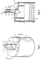
- Fig. 3 den Verschluss in einer Ansicht ähnlich Fig. 2, jedoch mit Darstellung der Ausgiesstülle in einer zweiten oder Schliesstellung, und
- Fig. 4 eine geschnittene Ansicht längs der Schnittlinie IV-IV in Fig. 3.
- 1 is a perspective view of a closure constructed according to the invention, showing the pouring spout in a first or open position,
- 2 shows a sectional view along the section line II-II in FIG. 1,
- Fig. 3 shows the closure in a view similar to Fig. 2, but showing the pouring spout in a second or closed position, and
- 4 shows a sectional view along the section line IV-IV in FIG. 3.
Der Verschluss nach der Erfindung umfasst, wie dargestellt, einen an einem Hals eines Behälters oder einer Flasche (nicht gezeigt) in geeigneter Weise, z.B. mittels eines in Fig. 2 gezeigten Schraubgewindes 13, befestigbaren Kappenteil 1 mit einer Oberwand 2 und einem inneren Dichtkonus 11, der dichtend in die Mündungsöffnung des Behälterhalses eingreifen kann. Alternativ kann der Kappenteil 1 auch in bekannter Weise Mittel zum Aufprellen auf einen Behälterhals aufweisen. Die Oberwand 2 bildet eine nach aussen und nach oben offene Ausnehmung 3, deren längere Achse radial zur Mittellinie steht und die im übrigen auf die Abmessung und Konfiguration einer nachfolgend beschriebenen am Kappenteil 1 angebundenen Ausgiesstülle 6 angepasst ist, so dass diese in der Ausnehmung 3 aufgenommen werden kann.As shown, the closure according to the invention also includes a cap part 1 which can be fastened to a neck of a container or a bottle (not shown) in a suitable manner, for example by means of a
Die Ausgiesstülle 6 kann eine steife plattenförmige Deckwand 8 umfassen, an deren Unterseite eine röhrförmige Ausformung mit einer Durchgangspassage 7 mit einem inneren und einem äusseren Ende vorgesehen ist. Die Deckwand 8 ist längs ihrer inneren Breitseite über ein Filmscharnier 9 einstückig mit der Oberwand 2 des Kappenteiles 1 verbunden und ermöglicht somit, dass die Ausgiesstülle 6 relativ zum Kappenteil 1 zwischen zwei Endstellungen geschwenkt werden kann, worauf nachfolgend noch näher eingegangen wird.The
Eine weitere Verbindung zwischen der Ausgiesstülle 6 und dem Kappenteil 1 ist durch eine biegsame Wandverdünnung oder Faltwand 10 geschaffen, die sich einerseits zwischen einer inneren Kante 14 der Ausgiesstülle 6 und einer äusseren Kante 15 eines inneren Endwandbereiches 4 der Ausnehmung 3 im Kappenteil 1 sowie andererseits beidseitig des Filmscharnieres 9 umfänglich erstreckt. Die Faltwand 10 umgibt zusammen mit dem Filmscharnier 9 einen nach aussen hermetisch abgeschirmten Bereich, der Teil eines die Durchgangspassage 7 umfassenden Strömungsweges ist, vgl. Pfeile A in Fig. 2, der das Innere des Kappenteiles 1 bzw. des Behälters mit der Aussenumgebung verbindet, wenn sich die Ausgiesstülle 6 in der in Fig. 1 und 2 gezeigten ersten Stellung befindet. In dieser Stellung kann die Durchgangspassage 7 der Ausgiesstülle 6 auf einer Verlängerung der Mittellinie des Verschlusses liegen.A further connection between the
Die Faltwand 10 ist in der ersten Stellung der Ausgiesstülle 6 gestreckt und kann sich bei der Schwenkung der Ausgiesstülle 6 in die zweite in Fig. 3 und 4 gezeigte Stellung mehrfach falten. Wenn erwünscht, kann die Faltung in definierter Weise durch in der Faltwand 10 vorgegebene Knicklinien erfolgen. Da die Formung des Verschlusses in der in Fig. 1 und 2 gezeigten ersten Stellung mit gestreckter Faltwand 10 erfolgt, hat diese das Bestreben, die erste Stellung einzunehmen, wenn keine äussere Kraft auf die Ausgiesstülle 6 einwirkt.The
Nachfolgend wird auf Fig. 3 und 4 näher Bezug genommen, die die Ausgiesstülle 6 in der zweiten oder Schliesstellung zeigen. In dieser Stellung ist die Ausgiesstülle 6 im wesentlichen in der Ausnehmung 3 des Kappenteiles 1 aufgenommen, wobei die Deckwand 8 im wesentlichen mit der Oberwand 2 des Kappenteiles 1 fluchtet. Ausserdem ist in dieser Stellung, wie vorerwähnt, der Strömungsweg A verschlossen. Hierzu ist an dem inneren Endwandbereich 4 der Ausnehmung 3 ein kugelkalottenartiger Dichtvorsprung oder - zapfen 5 angeformt, der in die Ausnehmung 3 hineinragt und in Bezug auf die Durchgangspassage 7 so ausgerichtet ist, dass er dichtend in deren inneren Endbereich eingreifen kann, wenn die Ausgiesstülle 6 von der ersten in die zweite Stellung geschwenkt wird. Am innere Endwandbereich 4 der Ausnehmung 3 ist ferner, wie bei 15 angedeutet, die Faltwand 10 am Kappenteil 1 angebunden.3 and 4, which show the
Aufgrund der vorbeschriebenen Anordnung des Dichtzapfens 5 kommt dieser bei der Schwenkung der Ausgiesstülle 6 von der ersten in die zweite Stellung zunächst aussenseitig mit der Faltwand 10 in Berührung, so dass sich diese am Dichtzapfen 5 anlegt und bei weiterer Schwenkung der Ausgiesstülle 6 in die zweite Stellung zusammen mit dem Dichtzapfen 5 in den inneren Endbereich der Durchgangspassage 7 hineingedrückt wird. Der Dichtzapfen 5 kommt daher nicht in unmittelbare Berührung mit dem abzudichtenden Fluid, wodurch Verschmutzungen des Dichtzapfens 5 vermieden werden, und andererseits schafft die Einbeziehung der Faltwand 10 zur Abdichtung der Durchgangspassage 7 eine erhöhte Dichtwirkung gegenüber einem dichtenden Eingreifen des Dichtzapfens alleine.Due to the above-described arrangement of the sealing
Der Dichtzapfen 5 wirkt ferner als Rastmittel, um die Ausgiesstülle 6 in der zweiten Stellung zu halten. Zusätzlich könnten auch gesonderte Rastmittel zwischen den Seitenwänden der Ausnehmung 3 des Kappenteiles 1 und der Deckwand 8 der Ausgiesstülle 6 vorgesehen werden, um diese in der zweiten Stellung zu halten.The sealing
In der zweiten Stellung der Ausgiesstülle 6 kann ferner deren innere Verbindungskante 14, längs der die Faltwand 10 angeformt ist, an dem inneren Endwandbereich 4 der Ausnehmung 3 bündig anliegen. Bei einer kreissegmentförmigen Querschnittskonfiguration der Ausgiesstülle 6 kann daher die Verbindungskante 14 einen im wesentlichen sichelförmigen Verlauf haben und ist der Endwandbereich 4 der Ausnehmung 3 entsprechend konvex gewölbt. Es versteht sich, dass auch andere einander angepasste Konfigurationen für die Verbindungskante 14 und den inneren Endwandbereich 4 vorgesehen werden können.In the second position of the
Zur leichteren Handhabung des Verschlusses kann die Deckwand 8 der Ausgiesstülle 6 etwas über das äussere Ende der Durchgangspassage 7 hinaus verlängert sein, so dass eine Greiflasche 12 gebildet ist, die von einem Finger einer Hand zur Schwenkung der Ausgiesstülle 6 unterfasst werden kann.For easier handling of the closure, the
Der erfindungsgemässe Verschluss ist ein im Spritzgiessverfahren einstückig geformtes Kunststoffteil, wobei die Ausformung vorzugsweise in der in Fig. 1 und 2 gezeigten ersten Stellung der Ausgiesstülle 6 mit gestreckter Faltwand 10 erfolgt.The closure according to the invention is a plastic part molded in one piece in the injection molding process, the molding preferably taking place in the first position of the
Claims (5)
- A closure for receptacles or the like comprising mountable on said receptacle a cap part having a pouring spout which for swivelling between a first and second position is integrally connected at one inner end circumferentially to said cap part by a film-type hinge and is otherwise integrally connected by a flexible folding wall, and a through-passage as part of a flow-path between the interior of said cap part and the outer side, said through-passage being open in the first position of said pouring spout and sealed off in the second position by a sealing plug engaging an end portion of said through-passage, said sealing plug being disposed on said cap part with reference to the second position of said pouring spout in a substantially oriented relation to said through-passage characterized in that said sealing plug (5) is provided on the inner side end of said pouring spout (6) and outside said flow-path (A) such that on swivelling said pouring spout into the second position a portion of said folding wall (10) can be forced inwards by said sealing plug into the inner end portion of said through-passage (7).
- The closure as set forth in claim 1, characterized in that said sealing plug (5) is formed as a latching plug for releasably fixing said pouring spout (6) in the second position.
- The closure as set forth in claim 1 or 2, characterized in that said pouring spout (6) is received in the second position in a recess (3) of said cap part (1) having an inner end wall portion (4) which carries said sealing plug (5).
- The closure as set forth in claim 3, characterized in that said inner end wall portion (4) has a convex configuration adapted to a connecting edge (14) between said folding wall (10) and said pouring spout (6).
- The closure as set forth in any of the preceding claims, characterized in that said pouring spout (6) comprises a stiff plate-shaped cover wall (8) having a grip tab (12).
Applications Claiming Priority (3)
| Application Number | Priority Date | Filing Date | Title |
|---|---|---|---|
| DE9207591U DE9207591U1 (en) | 1992-06-04 | 1992-06-04 | |
| DE9207591U | 1992-06-04 | ||
| PCT/EP1993/001416 WO1993024387A1 (en) | 1992-06-04 | 1993-06-04 | Closure for containers or the like |
Publications (2)
| Publication Number | Publication Date |
|---|---|
| EP0596096A1 EP0596096A1 (en) | 1994-05-11 |
| EP0596096B1 true EP0596096B1 (en) | 1996-04-17 |
Family
ID=6880243
Family Applications (1)
| Application Number | Title | Priority Date | Filing Date |
|---|---|---|---|
| EP93912888A Expired - Lifetime EP0596096B1 (en) | 1992-06-04 | 1993-06-04 | Closure for containers or the like |
Country Status (7)
| Country | Link |
|---|---|
| EP (1) | EP0596096B1 (en) |
| JP (1) | JPH06511458A (en) |
| AT (1) | ATE136864T1 (en) |
| AU (1) | AU4310093A (en) |
| DE (2) | DE9207591U1 (en) |
| ES (1) | ES2087745T3 (en) |
| WO (1) | WO1993024387A1 (en) |
Family Cites Families (4)
| Publication number | Priority date | Publication date | Assignee | Title |
|---|---|---|---|---|
| FR2355728A1 (en) * | 1976-06-22 | 1978-01-20 | Lima Castro Netto E De | Liquid container closure with fixed and pivotable sections - with lock for holding pivotable section in bent position |
| US4216880A (en) * | 1978-06-28 | 1980-08-12 | Drelichowski Marek K | Collapsible spout for dispensing fluent materials |
| GB2098184B (en) * | 1981-01-26 | 1984-12-12 | Dark Richard C G | Dispensing closure for fluent material |
| DE3104561A1 (en) * | 1981-02-10 | 1982-08-26 | Fa. Robert Finke, 5950 Finnentrop | Container closure |
-
1992
- 1992-06-04 DE DE9207591U patent/DE9207591U1/de not_active Expired - Lifetime
-
1993
- 1993-06-04 AU AU43100/93A patent/AU4310093A/en not_active Abandoned
- 1993-06-04 JP JP6500224A patent/JPH06511458A/en active Pending
- 1993-06-04 EP EP93912888A patent/EP0596096B1/en not_active Expired - Lifetime
- 1993-06-04 WO PCT/EP1993/001416 patent/WO1993024387A1/en active IP Right Grant
- 1993-06-04 AT AT93912888T patent/ATE136864T1/en not_active IP Right Cessation
- 1993-06-04 DE DE59302255T patent/DE59302255D1/en not_active Expired - Fee Related
- 1993-06-04 ES ES93912888T patent/ES2087745T3/en not_active Expired - Lifetime
Also Published As
| Publication number | Publication date |
|---|---|
| DE9207591U1 (en) | 1992-08-20 |
| JPH06511458A (en) | 1994-12-22 |
| ATE136864T1 (en) | 1996-05-15 |
| ES2087745T3 (en) | 1996-07-16 |
| AU4310093A (en) | 1993-12-30 |
| DE59302255D1 (en) | 1996-05-23 |
| EP0596096A1 (en) | 1994-05-11 |
| WO1993024387A1 (en) | 1993-12-09 |
Similar Documents
| Publication | Publication Date | Title |
|---|---|---|
| DE19832799B4 (en) | Hinged cap | |
| EP2242697B1 (en) | Cover of a container | |
| EP1427646B1 (en) | Dispenser closure for a container that contains a flowable product | |
| CH661488A5 (en) | PLASTIC LOCK. | |
| DE2934711A1 (en) | RELOCKABLE LIQUID CONTAINER | |
| DE4334740A1 (en) | Closure arrangement for a drop dispensing tip | |
| EP1503942A1 (en) | Hinged lid closure provided with a tamper-evident element for a container containing a free-flowing product | |
| WO1998055369A1 (en) | Single-piece plastic lid | |
| WO1998045190A1 (en) | Pouring spout for a plastic bag | |
| EP0515348B1 (en) | Tamper evident closure | |
| EP0280142A1 (en) | Container closure for the storage of liquid products | |
| EP0580883B1 (en) | Container closure | |
| EP0371307A1 (en) | Discharge means for packaging containers, particularly for bag-in-box containers | |
| EP0596096B1 (en) | Closure for containers or the like | |
| CH619413A5 (en) | Plastic closure for fixed and deformable containers | |
| EP0160981A2 (en) | Suspension device for a container provided with a closure | |
| DE3545548A1 (en) | WARRANTY CLOSURE | |
| EP0320808A1 (en) | Plastic closure for open containers | |
| DE19652148C2 (en) | Containers, especially bottles | |
| DE19525620A1 (en) | Opener and seal for paper cartons containing juices, milk, household and technical fluids | |
| EP1460000A1 (en) | Hinged closure | |
| EP0020987B1 (en) | Closure for tubes, bottles and the like | |
| DE10229257C1 (en) | Bottle cap has base section with lower inlet cooperating with slit in rotating tap, lower inlet being covered by security strip which is torn off when bottle is first used | |
| EP0624526B1 (en) | Container for liquid or pasty contents | |
| DE19711578C2 (en) | Device for opening and reclosing containers |
Legal Events
| Date | Code | Title | Description |
|---|---|---|---|
| PUAI | Public reference made under article 153(3) epc to a published international application that has entered the european phase |
Free format text: ORIGINAL CODE: 0009012 |
|
| 17P | Request for examination filed |
Effective date: 19940105 |
|
| AK | Designated contracting states |
Kind code of ref document: A1 Designated state(s): AT BE CH DE DK ES FR GB IT LI NL |
|
| 17Q | First examination report despatched |
Effective date: 19950620 |
|
| GRAH | Despatch of communication of intention to grant a patent |
Free format text: ORIGINAL CODE: EPIDOS IGRA |
|
| GRAA | (expected) grant |
Free format text: ORIGINAL CODE: 0009210 |
|
| AK | Designated contracting states |
Kind code of ref document: B1 Designated state(s): AT BE CH DE DK ES FR GB IT LI NL |
|
| PG25 | Lapsed in a contracting state [announced via postgrant information from national office to epo] |
Ref country code: NL Free format text: LAPSE BECAUSE OF FAILURE TO SUBMIT A TRANSLATION OF THE DESCRIPTION OR TO PAY THE FEE WITHIN THE PRESCRIBED TIME-LIMIT Effective date: 19960417 Ref country code: DK Effective date: 19960417 |
|
| REF | Corresponds to: |
Ref document number: 136864 Country of ref document: AT Date of ref document: 19960515 Kind code of ref document: T |
|
| PGFP | Annual fee paid to national office [announced via postgrant information from national office to epo] |
Ref country code: CH Payment date: 19960521 Year of fee payment: 4 |
|
| REF | Corresponds to: |
Ref document number: 59302255 Country of ref document: DE Date of ref document: 19960523 |
|
| PGFP | Annual fee paid to national office [announced via postgrant information from national office to epo] |
Ref country code: DE Payment date: 19960619 Year of fee payment: 4 |
|
| REG | Reference to a national code |
Ref country code: ES Ref legal event code: BA2A Ref document number: 2087745 Country of ref document: ES Kind code of ref document: T3 |
|
| PGFP | Annual fee paid to national office [announced via postgrant information from national office to epo] |
Ref country code: AT Payment date: 19960628 Year of fee payment: 4 |
|
| REG | Reference to a national code |
Ref country code: CH Ref legal event code: NV Representative=s name: ROTTMANN, ZIMMERMANN + PARTNER AG |
|
| ITF | It: translation for a ep patent filed |
Owner name: STUDIO JAUMANN |
|
| PGFP | Annual fee paid to national office [announced via postgrant information from national office to epo] |
Ref country code: BE Payment date: 19960711 Year of fee payment: 4 |
|
| REG | Reference to a national code |
Ref country code: ES Ref legal event code: FG2A Ref document number: 2087745 Country of ref document: ES Kind code of ref document: T3 |
|
| GBT | Gb: translation of ep patent filed (gb section 77(6)(a)/1977) |
Effective date: 19960618 |
|
| ET | Fr: translation filed | ||
| NLV1 | Nl: lapsed or annulled due to failure to fulfill the requirements of art. 29p and 29m of the patents act | ||
| PLBE | No opposition filed within time limit |
Free format text: ORIGINAL CODE: 0009261 |
|
| STAA | Information on the status of an ep patent application or granted ep patent |
Free format text: STATUS: NO OPPOSITION FILED WITHIN TIME LIMIT |
|
| 26N | No opposition filed | ||
| PGFP | Annual fee paid to national office [announced via postgrant information from national office to epo] |
Ref country code: FR Payment date: 19970416 Year of fee payment: 5 |
|
| PGFP | Annual fee paid to national office [announced via postgrant information from national office to epo] |
Ref country code: GB Payment date: 19970527 Year of fee payment: 5 |
|
| PG25 | Lapsed in a contracting state [announced via postgrant information from national office to epo] |
Ref country code: AT Effective date: 19970604 |
|
| PGFP | Annual fee paid to national office [announced via postgrant information from national office to epo] |
Ref country code: ES Payment date: 19970618 Year of fee payment: 5 |
|
| PG25 | Lapsed in a contracting state [announced via postgrant information from national office to epo] |
Ref country code: LI Free format text: LAPSE BECAUSE OF NON-PAYMENT OF DUE FEES Effective date: 19970630 Ref country code: CH Free format text: LAPSE BECAUSE OF NON-PAYMENT OF DUE FEES Effective date: 19970630 Ref country code: BE Effective date: 19970630 |
|
| BERE | Be: lapsed |
Owner name: GEORG MENSHEN G.M.B.H. + CO. K.G. Effective date: 19970630 |
|
| REG | Reference to a national code |
Ref country code: CH Ref legal event code: PL |
|
| PG25 | Lapsed in a contracting state [announced via postgrant information from national office to epo] |
Ref country code: DE Free format text: LAPSE BECAUSE OF NON-PAYMENT OF DUE FEES Effective date: 19980303 |
|
| PG25 | Lapsed in a contracting state [announced via postgrant information from national office to epo] |
Ref country code: GB Free format text: LAPSE BECAUSE OF NON-PAYMENT OF DUE FEES Effective date: 19980604 |
|
| PG25 | Lapsed in a contracting state [announced via postgrant information from national office to epo] |
Ref country code: ES Free format text: LAPSE BECAUSE OF NON-PAYMENT OF DUE FEES Effective date: 19980605 |
|
| GBPC | Gb: european patent ceased through non-payment of renewal fee |
Effective date: 19980604 |
|
| PG25 | Lapsed in a contracting state [announced via postgrant information from national office to epo] |
Ref country code: FR Free format text: LAPSE BECAUSE OF NON-PAYMENT OF DUE FEES Effective date: 19990226 |
|
| REG | Reference to a national code |
Ref country code: FR Ref legal event code: ST |
|
| REG | Reference to a national code |
Ref country code: ES Ref legal event code: FD2A Effective date: 20000503 |
|
| PG25 | Lapsed in a contracting state [announced via postgrant information from national office to epo] |
Ref country code: IT Free format text: LAPSE BECAUSE OF NON-PAYMENT OF DUE FEES;WARNING: LAPSES OF ITALIAN PATENTS WITH EFFECTIVE DATE BEFORE 2007 MAY HAVE OCCURRED AT ANY TIME BEFORE 2007. THE CORRECT EFFECTIVE DATE MAY BE DIFFERENT FROM THE ONE RECORDED. Effective date: 20050604 |