EP0595879B1 - Coating substrates - Google Patents
Coating substrates Download PDFInfo
- Publication number
- EP0595879B1 EP0595879B1 EP92915400A EP92915400A EP0595879B1 EP 0595879 B1 EP0595879 B1 EP 0595879B1 EP 92915400 A EP92915400 A EP 92915400A EP 92915400 A EP92915400 A EP 92915400A EP 0595879 B1 EP0595879 B1 EP 0595879B1
- Authority
- EP
- European Patent Office
- Prior art keywords
- substrate
- plating solution
- coating
- plating
- substrates
- Prior art date
- Legal status (The legal status is an assumption and is not a legal conclusion. Google has not performed a legal analysis and makes no representation as to the accuracy of the status listed.)
- Expired - Lifetime
Links
Images



Classifications
-
- C—CHEMISTRY; METALLURGY
- C23—COATING METALLIC MATERIAL; COATING MATERIAL WITH METALLIC MATERIAL; CHEMICAL SURFACE TREATMENT; DIFFUSION TREATMENT OF METALLIC MATERIAL; COATING BY VACUUM EVAPORATION, BY SPUTTERING, BY ION IMPLANTATION OR BY CHEMICAL VAPOUR DEPOSITION, IN GENERAL; INHIBITING CORROSION OF METALLIC MATERIAL OR INCRUSTATION IN GENERAL
- C23C—COATING METALLIC MATERIAL; COATING MATERIAL WITH METALLIC MATERIAL; SURFACE TREATMENT OF METALLIC MATERIAL BY DIFFUSION INTO THE SURFACE, BY CHEMICAL CONVERSION OR SUBSTITUTION; COATING BY VACUUM EVAPORATION, BY SPUTTERING, BY ION IMPLANTATION OR BY CHEMICAL VAPOUR DEPOSITION, IN GENERAL
- C23C18/00—Chemical coating by decomposition of either liquid compounds or solutions of the coating forming compounds, without leaving reaction products of surface material in the coating; Contact plating
- C23C18/16—Chemical coating by decomposition of either liquid compounds or solutions of the coating forming compounds, without leaving reaction products of surface material in the coating; Contact plating by reduction or substitution, e.g. electroless plating
- C23C18/1601—Process or apparatus
- C23C18/1633—Process of electroless plating
- C23C18/1675—Process conditions
- C23C18/168—Control of temperature, e.g. temperature of bath, substrate
-
- C—CHEMISTRY; METALLURGY
- C23—COATING METALLIC MATERIAL; COATING MATERIAL WITH METALLIC MATERIAL; CHEMICAL SURFACE TREATMENT; DIFFUSION TREATMENT OF METALLIC MATERIAL; COATING BY VACUUM EVAPORATION, BY SPUTTERING, BY ION IMPLANTATION OR BY CHEMICAL VAPOUR DEPOSITION, IN GENERAL; INHIBITING CORROSION OF METALLIC MATERIAL OR INCRUSTATION IN GENERAL
- C23C—COATING METALLIC MATERIAL; COATING MATERIAL WITH METALLIC MATERIAL; SURFACE TREATMENT OF METALLIC MATERIAL BY DIFFUSION INTO THE SURFACE, BY CHEMICAL CONVERSION OR SUBSTITUTION; COATING BY VACUUM EVAPORATION, BY SPUTTERING, BY ION IMPLANTATION OR BY CHEMICAL VAPOUR DEPOSITION, IN GENERAL
- C23C18/00—Chemical coating by decomposition of either liquid compounds or solutions of the coating forming compounds, without leaving reaction products of surface material in the coating; Contact plating
- C23C18/16—Chemical coating by decomposition of either liquid compounds or solutions of the coating forming compounds, without leaving reaction products of surface material in the coating; Contact plating by reduction or substitution, e.g. electroless plating
- C23C18/1601—Process or apparatus
- C23C18/1633—Process of electroless plating
- C23C18/1655—Process features
- C23C18/1664—Process features with additional means during the plating process
- C23C18/1667—Radiant energy, e.g. laser
-
- C—CHEMISTRY; METALLURGY
- C23—COATING METALLIC MATERIAL; COATING MATERIAL WITH METALLIC MATERIAL; CHEMICAL SURFACE TREATMENT; DIFFUSION TREATMENT OF METALLIC MATERIAL; COATING BY VACUUM EVAPORATION, BY SPUTTERING, BY ION IMPLANTATION OR BY CHEMICAL VAPOUR DEPOSITION, IN GENERAL; INHIBITING CORROSION OF METALLIC MATERIAL OR INCRUSTATION IN GENERAL
- C23C—COATING METALLIC MATERIAL; COATING MATERIAL WITH METALLIC MATERIAL; SURFACE TREATMENT OF METALLIC MATERIAL BY DIFFUSION INTO THE SURFACE, BY CHEMICAL CONVERSION OR SUBSTITUTION; COATING BY VACUUM EVAPORATION, BY SPUTTERING, BY ION IMPLANTATION OR BY CHEMICAL VAPOUR DEPOSITION, IN GENERAL
- C23C18/00—Chemical coating by decomposition of either liquid compounds or solutions of the coating forming compounds, without leaving reaction products of surface material in the coating; Contact plating
- C23C18/16—Chemical coating by decomposition of either liquid compounds or solutions of the coating forming compounds, without leaving reaction products of surface material in the coating; Contact plating by reduction or substitution, e.g. electroless plating
- C23C18/1601—Process or apparatus
- C23C18/1633—Process of electroless plating
- C23C18/1675—Process conditions
- C23C18/1676—Heating of the solution
-
- C—CHEMISTRY; METALLURGY
- C23—COATING METALLIC MATERIAL; COATING MATERIAL WITH METALLIC MATERIAL; CHEMICAL SURFACE TREATMENT; DIFFUSION TREATMENT OF METALLIC MATERIAL; COATING BY VACUUM EVAPORATION, BY SPUTTERING, BY ION IMPLANTATION OR BY CHEMICAL VAPOUR DEPOSITION, IN GENERAL; INHIBITING CORROSION OF METALLIC MATERIAL OR INCRUSTATION IN GENERAL
- C23C—COATING METALLIC MATERIAL; COATING MATERIAL WITH METALLIC MATERIAL; SURFACE TREATMENT OF METALLIC MATERIAL BY DIFFUSION INTO THE SURFACE, BY CHEMICAL CONVERSION OR SUBSTITUTION; COATING BY VACUUM EVAPORATION, BY SPUTTERING, BY ION IMPLANTATION OR BY CHEMICAL VAPOUR DEPOSITION, IN GENERAL
- C23C18/00—Chemical coating by decomposition of either liquid compounds or solutions of the coating forming compounds, without leaving reaction products of surface material in the coating; Contact plating
- C23C18/16—Chemical coating by decomposition of either liquid compounds or solutions of the coating forming compounds, without leaving reaction products of surface material in the coating; Contact plating by reduction or substitution, e.g. electroless plating
- C23C18/1601—Process or apparatus
- C23C18/1633—Process of electroless plating
- C23C18/1689—After-treatment
- C23C18/1692—Heat-treatment
-
- C—CHEMISTRY; METALLURGY
- C25—ELECTROLYTIC OR ELECTROPHORETIC PROCESSES; APPARATUS THEREFOR
- C25D—PROCESSES FOR THE ELECTROLYTIC OR ELECTROPHORETIC PRODUCTION OF COATINGS; ELECTROFORMING; APPARATUS THEREFOR
- C25D21/00—Processes for servicing or operating cells for electrolytic coating
- C25D21/02—Heating or cooling
Definitions
- the invention relates to methods of plating substrates and in particular to methods of coating substrates by electroless plating.
- a substrate which may be a metallic alloy, composite or non-metallic substrate, is immersed in a plating solution to provide the substrate with a desired coating.
- the coating may be obtained by the application of an electric current (electrolysis) or without such a current (electroless).
- electroless plating the substrate is inserted in a container of a suitable plating solution which is in turn inserted in a thermostatically controlled water bath. The solution is heated to a temperature and for a time sufficient to provide a required coating thickness.
- the rate of deposition and the grain structure of the plating are controlled by adjusting the current (electrolytic plating) or by the electrolyte temperature (electroless plating).
- the current electrolytic plating
- electrolyte temperature electrolyte temperature
- a method of depositing a coating on a substrate comprising inserting a substrate into a plating solution for coating of the substrate and then heating the plating solution in a chamber by a microwave source during the plating process to produce a required coating.
- the method also comprises heating the plating solution by the microwave source prior to insertion of the substrate.
- the method also includes adjusting the power output of the microwave source to control the temperature of the plating solution.
- the method may also comprise controlling the temperature to a constant temperature throughout the coating process.
- the method may comprise pulsing the power to the microwave source.
- the method may also include heat treating the coated substrate.
- the plating process is an electroless plating process.
- the apparatus for electroless plating comprises a domestic microwave oven 10 having a maximum power output of 500W from a microwave source 12.
- the oven is equipped with an internal turntable 11 and a microwave stirrer to ensure an even distribution of energy within the chamber.
- the oven 10 is modified to achieve continuous irradiation with variable power by use of a Variac 13.
- thermometer An accurate indication of the temperature of the plating solution can be readily achieved by use of a miniature gas thermometer.
- This is connected, by a capillary 14, to a pressure transducer 15 mounted outside the microwave cavity.
- the output from the transducer 15 is connected to a digital voltmeter 16.
- a gas thermometer of known dimensions as described in the article by G. Bond, R.B. Moyes, S.D. Pollington and D.A. Whan, Meas. Sci. Technol . 2 (1991), 571-572, and with air as the operating gas
- calibration of the thermometer can be achieved by reference to fixed points or by the simultaneous immersion of the gas thermometer and a thermocouple in a heated liquid in the absence of microwave energy.
- the thermometer is inserted into the bath and by monitoring of the output from the pressure transducer 15 a constant temperature can be maintained.
- a 500 millilitre beaker 17 is used to contain plating solutions and substrates described below.
- the substrates had the following compositions and dimensions:- Substrate No. Material (cm) width (cm) length (mm) thickness 1 Copper(Goodfellow,99.9% purity, half hard) 2 8 0.25 2 Mild Steel 2 8 0.8 3 Stainless Steel 2 8 0.8
- the two plating solutions compositions used were as follows:- PLATING SOLUTION 1 Nickel sulphate 30g/l Sodium hypophosphite 20g/l Lactic acid 25g/l Propionic acid 5g/l Lead as lead nitrate 4mg/l pH 4.5 PLATING SOLUTION 2 OMI proprietary solution Enplate NI 425A,425B (sold by OMI-IMASA Marketing(Europe)Ltd) pH (at 90°C) 5
- each substrate was pre-treated as follows. First, the substrate was soaked in Enbond 808 (trade mark) at 80°C for 3 minutes and then rinsed. The substrate was then soaked in Enbond 808 (trade mark) and subjected to anodic electrolytic cleaning for 3 minutes at 80°C at a current density of 6 A/dm2 and then rinsed. It was then dipped in tin chloride (SnCl2), rinsed, dipped in palladium chloride (PdCl2) and rinsed.
- SnCl2 tin chloride
- PdCl2 palladium chloride
- the substrates were then treated by two different methods.
- the plating solution (either plating solution 1 or plating solution 2) was placed in a beaker and the beaker placed in a thermostatically controlled water bath. The bath was kept at a temperature of 80°C (plating solution 1) or 85°C (plating solution 2), and the rate of deposition of the coating measured with a total treatment time of two hours.
- the appropriate plating solution was placed in the beaker 17 with the substrate and the beaker placed on the tray 11 of the microwave chamber 10 described above with reference to Figure 1.
- the plating solution may be heated using the microwave source prior to insertion of the substrate.
- the microwave power source was turned on and the required temperature (80°C for plating solution 1, 85°C for plating solution 2) maintained by use of the Variac 13. Again, the plating rate was measured with a total treatment time of two hours.
- the use of the microwave power source was found to obviate the need for agitation of the plating solution. In addition, the fact that the chamber is closed was found to allow containment of any mess that may arise during the process.
- the plating rate was greater with method 2 (the method according to the invention) than with method 1 (the prior art method).
- the proportion of nickel to phosphorus in the coating was substantially unchanged by use of method 2.
- the morphology of the nickel-phosphorus coating on the copper and mild steel and stainless steel substrates coated by method 1 are comparable to those coated by method 2.
- the surface coat texture of the coatings of method 2 are superior to those of method 1.
- the surface topography of the coating on the stainless steel substrate for the two methods tend to differ slightly, which can be taken as further proof that surface texture is dependent on substrate type.
- Figures 3a,3b and 3c show the surface topography of substrates after treatment in plating solution 2. These confirm that the copper substrate was not coated by either method 1 or method 2. This could be due to the fact that plating solution 2 is a proprietary solution designed to be used on substrates other than copper, according to the manufacturer's indications.
- Figure 3c confirms that the coating obtained on a stainless steel substrate by method 1 was patchy and that no deposition takes place with method 2. Again, this may be because plating solution 2 is said to be designed for substrates other than stainless steel.
- substrates coated according to method 2 are generally harder than substrates treated by method 1. After heat treatment, the hardness of substrates treated by method 2 remain superior to the hardness of substrates treated by method 1.
- the mean microhardnesses, ⁇ HK indicate that the variations in values do not overlap so implying that consistent improvements in hardness can be expected from method 2.
- Figure 4 shows the surface topography of the substrates of examples 1, 2, 5, 6, 9 and 10 after being heat treated at 400°C for 80 minutes.
- Figure 4 shows substrates of examples 7 and 8 heat treated at 400°C for 80 minutes.
- the use of a microwave power source for heating the plating solution produces increased plating rates as compared with a water bath method.
- the use of a microwave source can allow satisfactory plating rates to be achieved at lower temperatures than with a water bath.
- the use of a microwave power source can allow improvements in grain structure (and hardness) to be achieved at lower temperatures than with a water bath. This can prolong the life of the plating solution and avoid instability in the plating solution.
- the substrates described above are metals or metal alloys, the substrates could be of any other suitable material.
- microwave heating can also bring improvements in grain structure and plating rates when used with electrolytic plating and other anodic electrolytic processes.
- the plating solution used could be any suitable plating solution, such as a plating solution for copper plating a substrate.
Landscapes
- Chemical & Material Sciences (AREA)
- Chemical Kinetics & Catalysis (AREA)
- Engineering & Computer Science (AREA)
- Materials Engineering (AREA)
- Metallurgy (AREA)
- Organic Chemistry (AREA)
- General Chemical & Material Sciences (AREA)
- Mechanical Engineering (AREA)
- Electrochemistry (AREA)
- Physics & Mathematics (AREA)
- Optics & Photonics (AREA)
- Chemically Coating (AREA)
Abstract
Description
- The invention relates to methods of plating substrates and in particular to methods of coating substrates by electroless plating.
- In plating methods, a substrate, which may be a metallic alloy, composite or non-metallic substrate, is immersed in a plating solution to provide the substrate with a desired coating. The coating may be obtained by the application of an electric current (electrolysis) or without such a current (electroless). In electroless plating, the substrate is inserted in a container of a suitable plating solution which is in turn inserted in a thermostatically controlled water bath. The solution is heated to a temperature and for a time sufficient to provide a required coating thickness.
- In such plating, for a particular plating solution the rate of deposition and the grain structure of the plating are controlled by adjusting the current (electrolytic plating) or by the electrolyte temperature (electroless plating). However, such increases in current/ temperature can have disadvantages in reducing the life of the plating solution.
- According to the invention, there is provided a method of depositing a coating on a substrate comprising inserting a substrate into a plating solution for coating of the substrate and then heating the plating solution in a chamber by a microwave source during the plating process to produce a required coating.
- Preferably, the method also comprises heating the plating solution by the microwave source prior to insertion of the substrate.
- It has been found that by using a microwave source for heating improvements in deposition rate and grain structure can be achieved.
- Preferably the method also includes adjusting the power output of the microwave source to control the temperature of the plating solution.
- The method may also comprise controlling the temperature to a constant temperature throughout the coating process. Alternatively, the method may comprise pulsing the power to the microwave source. The method may also include heat treating the coated substrate.
- Preferably, the plating process is an electroless plating process.
- The following is a more detailed description of some embodiments of the invention, by way of example, reference being made to the accompanying drawing and electron micrographs in which:-
- Figure 1 is a schematic view of an apparatus for coating a metallic substrate by an electroless process and including a source of microwave power,
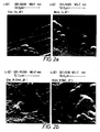
- Figure 2a is two micrographs of the crystal structure of a copper substrate with a nickel-phosphorus coating from a first plating solution applied by a known method (left) and by a first exemplary method according to the invention (right),
- Figure 2b is two scanning electron micrographs of the crystal structure of a mild steel substrate with a nickel-phosphorus coating from a first plating solution applied by a known method (left) and by a first exemplary method according to the invention (right),
- Figure 2c is two micrographs of the crystal structure of a stainless steel substrate with a nickel-phosphorus coating from a first plating solution applied by a known method (left) and by a first exemplary method according to the invention (right),
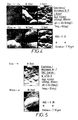
- Figure 3a is two scanning electron micrographs of the crystal structure of a copper substrate after treatment in a second plating solution by a known method (left) and by a second exemplary method according to the invention (right),
- Figure 3b is two scanning electron micrographs of the crystal structure of a mild steel substrate after treatment in a second plating solution by a known method (left) and by a second exemplary method according to the invention (right),
- Figure 3c is two scanning electron micrographs of the crystal structure of a stainless steel substrate after treatment in a second plating solution by a known method (left) and by a second exemplary method according to the invention (right),
- Figure 4 is six scanning electron micrographs at a magnification of x2000 showing the surface topography, and in three vertically arranged pairs, each pair showing respectively the topography of a copper substrate, a mild steel substrate and a stainless steel substrate each with a nickel-phosphorus coating from a first plating solution applied by a known method (upper micrographs) and a third exemplary method according to the invention (lower micrographs),
- Figure 5 is two scanning electron micrographs at a magnification of x2000 of the surface topography of a mild steel substrate with a nickel-phosphorus coating formed from a second plating solution applied by a known method (above) and by a fourth exemplary method according to the invention (below).
- Referring first to Figure 1, the apparatus for electroless plating comprises a
domestic microwave oven 10 having a maximum power output of 500W from amicrowave source 12. The oven is equipped with aninternal turntable 11 and a microwave stirrer to ensure an even distribution of energy within the chamber. Theoven 10 is modified to achieve continuous irradiation with variable power by use of a Variac 13. - An accurate indication of the temperature of the plating solution can be readily achieved by use of a miniature gas thermometer. This is connected, by a capillary 14, to a
pressure transducer 15 mounted outside the microwave cavity. The output from thetransducer 15 is connected to adigital voltmeter 16. In this way by using a gas thermometer of known dimensions as described in the article by G. Bond, R.B. Moyes, S.D. Pollington and D.A. Whan, Meas. Sci. Technol. 2 (1991), 571-572, and with air as the operating gas, calibration of the thermometer can be achieved by reference to fixed points or by the simultaneous immersion of the gas thermometer and a thermocouple in a heated liquid in the absence of microwave energy. During the course of the experiment, the thermometer is inserted into the bath and by monitoring of the output from the pressure transducer 15 a constant temperature can be maintained. - A 500
millilitre beaker 17 is used to contain plating solutions and substrates described below. - Tests were conducted using three different substrates and two different plating solutions.
- The substrates had the following compositions and dimensions:-
Substrate No. Material (cm) width (cm) length (mm) thickness 1 Copper(Goodfellow,99.9% purity, half hard) 2 8 0.25 2 Mild Steel 2 8 0.8 3 Stainless Steel 2 8 0.8 - The two plating solutions compositions used were as follows:-
PLATING SOLUTION 1Nickel sulphate 30g/l Sodium hypophosphite 20g/l Lactic acid 25g/l Propionic acid 5g/l Lead as lead nitrate 4mg/l pH 4.5 PLATING SOLUTION 2 OMI proprietary solution Enplate NI 425A,425B (sold by OMI-IMASA Marketing(Europe)Ltd) pH (at 90°C) 5 - Prior to coating, each substrate was pre-treated as follows. First, the substrate was soaked in Enbond 808 (trade mark) at 80°C for 3 minutes and then rinsed. The substrate was then soaked in Enbond 808 (trade mark) and subjected to anodic electrolytic cleaning for 3 minutes at 80°C at a current density of 6 A/dm² and then rinsed. It was then dipped in tin chloride (SnCl₂), rinsed, dipped in palladium chloride (PdCl₂) and rinsed.
- The substrates were then treated by two different methods. In the first method (method 1), the plating solution (either
plating solution 1 or plating solution 2) was placed in a beaker and the beaker placed in a thermostatically controlled water bath. The bath was kept at a temperature of 80°C (plating solution 1) or 85°C (plating solution 2), and the rate of deposition of the coating measured with a total treatment time of two hours. - In the second method (method 2), the appropriate plating solution was placed in the
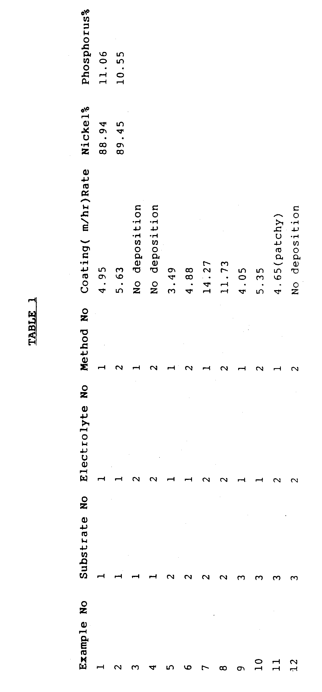
beaker 17 with the substrate and the beaker placed on thetray 11 of themicrowave chamber 10 described above with reference to Figure 1. The plating solution may be heated using the microwave source prior to insertion of the substrate. The microwave power source was turned on and the required temperature (80°C forplating solution - The results of these coating methods are set out in the accompanying Table 1.
- It will be seen that, for all substrates, the plating rate was greater with method 2 (the method according to the invention) than with method 1 (the prior art method). For copper, the proportion of nickel to phosphorus in the coating was substantially unchanged by use of method 2. As seen in Figures 2a, 2b and 2c, the morphology of the nickel-phosphorus coating on the copper and mild steel and stainless steel substrates coated by
method 1 are comparable to those coated by method 2. These Figures also indicate that different substrates can produce different coating structures for both methods. Nevertheless, the surface coat texture of the coatings of method 2 are superior to those ofmethod 1. The surface topography of the coating on the stainless steel substrate for the two methods (examples 9 and 10) tend to differ slightly, which can be taken as further proof that surface texture is dependent on substrate type. - It will be seen that, with plating solution 2, the coating rate on mild steel was greater with method 2 than with method 1 (examples 7 and 8). Coating was unsatisfactory on both copper and stainless steel with both methods.
- Figures 3a,3b and 3c show the surface topography of substrates after treatment in plating solution 2. These confirm that the copper substrate was not coated by either
method 1 or method 2. This could be due to the fact that plating solution 2 is a proprietary solution designed to be used on substrates other than copper, according to the manufacturer's indications. - Figure 3c confirms that the coating obtained on a stainless steel substrate by
method 1 was patchy and that no deposition takes place with method 2. Again, this may be because plating solution 2 is said to be designed for substrates other than stainless steel. - Substrates according to examples 1 and 2 were then taken and heat treated in a muffle furnace at 400°C for 80 minutes. Knoop microhardness measurements were carried out on the examples before and after heat treatment using a Leitz (trade mark) miniload Knoop microhardness tester.
- The results were as follows:-
Example No. Heat treated Average₆(HK₆) ΔHK 1 No 266.1 266.1±23.3 2 No 301.2 301.2±11.8 1 Yes 322.6 322.6±13.1 2 Yes 395.1 395.1±47.05 - It will be seen that even without heat treatment, substrates coated according to method 2 are generally harder than substrates treated by
method 1. After heat treatment, the hardness of substrates treated by method 2 remain superior to the hardness of substrates treated bymethod 1. The mean microhardnesses, Δ HK , indicate that the variations in values do not overlap so implying that consistent improvements in hardness can be expected from method 2. - Figure 4 shows the surface topography of the substrates of examples 1, 2, 5, 6, 9 and 10 after being heat treated at 400°C for 80 minutes. Figure 4 shows substrates of examples 7 and 8 heat treated at 400°C for 80 minutes. These clearly show that the structures after heat treatment become smoother. The hardness of the deposits is enhanced because smoothness is directly related to the grain size, i.e. the smaller the grain size the higher the hardness values. In addition, it can be seen that the coated substrates of method 2 have smoother coatings than those of
method 1 which account for the improved hardness of coated substrates according to method 2. - It will thus be seen that the use of a microwave power source for heating the plating solution produces increased plating rates as compared with a water bath method. Thus, the use of a microwave source can allow satisfactory plating rates to be achieved at lower temperatures than with a water bath. In addition, the use of a microwave power source can allow improvements in grain structure (and hardness) to be achieved at lower temperatures than with a water bath. This can prolong the life of the plating solution and avoid instability in the plating solution.
- Although the substrates described above are metals or metal alloys, the substrates could be of any other suitable material.
- The use of microwave heating can also bring improvements in grain structure and plating rates when used with electrolytic plating and other anodic electrolytic processes.
- It will be appreciated that the plating solution used could be any suitable plating solution, such as a plating solution for copper plating a substrate.
Claims (9)
- A method of depositing a coating on a substrate comprising inserting a substrate into a plating solution (17) for coating of the substrate and then heating the plating solution in a chamber by a microwave source (12) during the plating process to produce a required coating.
- A method according to claim 1 and further comprising heating the plating solution by the microwave source (12) prior to insertion of the substrate.
- A method according to claim 2 and comprising adjusting the power output of the microwave source (12) to control the temperature of the plating solution.
- A method according to claim 3 comprising controlling the temperature to a constant temperature throughout the coating process.
- A method according to claim 3 comprising pulsing the power to the microwave source.
- A method according to any one of claims 1 to 5 and further comprising heat-treating the coated substrate.
- A method according to any one of claims 1 to 6 wherein the plating process is an electroless plating process.
- A method according to any one of claims 1 to 7 wherein the substrate is a metallic substrate.
- A coated substrate when made by the method of any one of claims 1 to 8.
Applications Claiming Priority (3)
| Application Number | Priority Date | Filing Date | Title |
|---|---|---|---|
| GB9115655 | 1991-07-19 | ||
| GB9115655A GB2257715B (en) | 1991-07-19 | 1991-07-19 | Coating metallic substrates |
| PCT/GB1992/001316 WO1993002224A1 (en) | 1991-07-19 | 1992-07-17 | Coating substrates |
Publications (2)
| Publication Number | Publication Date |
|---|---|
| EP0595879A1 EP0595879A1 (en) | 1994-05-11 |
| EP0595879B1 true EP0595879B1 (en) | 1995-11-08 |
Family
ID=10698662
Family Applications (1)
| Application Number | Title | Priority Date | Filing Date |
|---|---|---|---|
| EP92915400A Expired - Lifetime EP0595879B1 (en) | 1991-07-19 | 1992-07-17 | Coating substrates |
Country Status (4)
| Country | Link |
|---|---|
| EP (1) | EP0595879B1 (en) |
| DE (1) | DE69205983T2 (en) |
| GB (1) | GB2257715B (en) |
| WO (1) | WO1993002224A1 (en) |
Families Citing this family (6)
| Publication number | Priority date | Publication date | Assignee | Title |
|---|---|---|---|---|
| ATE151821T1 (en) * | 1992-02-08 | 1997-05-15 | Lpw Anlagen Gmbh | SYSTEM FOR OPERATING A POWERLESS ELECTROCHEMICAL BATH WITH BATH HEATING BY MICROWAVES |
| US6692588B1 (en) * | 1999-07-12 | 2004-02-17 | Nutool, Inc. | Method and apparatus for simultaneously cleaning and annealing a workpiece |
| US8257781B1 (en) * | 2002-06-28 | 2012-09-04 | Novellus Systems, Inc. | Electroless plating-liquid system |
| CN100414001C (en) * | 2005-09-29 | 2008-08-27 | 陕西科技大学 | A method and device for preparing coating or film by microwave hydrothermal electrodeposition |
| JP4324639B2 (en) * | 2007-06-05 | 2009-09-02 | 株式会社ピカパワー | Silver ion-fixed product by microwave irradiation, silver ion-fixed method, and method for producing silver ion-fixed product |
| US10925603B2 (en) | 2017-11-14 | 2021-02-23 | Covidien Lp | Reload with articulation stabilization system |
Family Cites Families (6)
| Publication number | Priority date | Publication date | Assignee | Title |
|---|---|---|---|---|
| GB1008014A (en) * | 1962-03-08 | 1965-10-22 | Standard Telephones Cables Ltd | Method to heat metals for evaporation purposes and/or for diffusion |
| US3652322A (en) * | 1970-09-03 | 1972-03-28 | Continental Oil Co | Method for controlling the heating of a metal immersed in a plating solution |
| IT1061768B (en) * | 1976-06-18 | 1983-04-30 | Euratom | DIAPHRAGM SAFETY VALVE WITH PRECISE ELEMENT DETERMINATION OF BREAKING PRESSURE |
| US4265721A (en) * | 1980-05-05 | 1981-05-05 | Hackmyer Saul A | Commercial hydrogen gas production by electrolysis of water while being subjected to microwave energy |
| DE3138072C1 (en) * | 1981-09-24 | 1982-11-04 | Siemens AG, 1000 Berlin und 8000 München | Process for heating aluminizing baths with aprotic electrolit systems |
| US4807559A (en) * | 1987-09-02 | 1989-02-28 | Ajax Magnethermic Corporation | Apparatus for alloying of coatings |
-
1991
- 1991-07-19 GB GB9115655A patent/GB2257715B/en not_active Expired - Fee Related
-
1992
- 1992-07-17 WO PCT/GB1992/001316 patent/WO1993002224A1/en not_active Ceased
- 1992-07-17 DE DE69205983T patent/DE69205983T2/en not_active Expired - Fee Related
- 1992-07-17 EP EP92915400A patent/EP0595879B1/en not_active Expired - Lifetime
Also Published As
| Publication number | Publication date |
|---|---|
| GB2257715B (en) | 1994-06-29 |
| GB9115655D0 (en) | 1991-09-04 |
| WO1993002224A1 (en) | 1993-02-04 |
| DE69205983D1 (en) | 1995-12-14 |
| EP0595879A1 (en) | 1994-05-11 |
| GB2257715A (en) | 1993-01-20 |
| DE69205983T2 (en) | 1996-05-23 |
Similar Documents
| Publication | Publication Date | Title |
|---|---|---|
| US2739107A (en) | Applying protective metal coatings on refractory metals | |
| WO1993002224A1 (en) | Coating substrates | |
| US20080302667A1 (en) | Method and apparatus for airfoil electroplating, and airfoil | |
| US2929766A (en) | Plating of iridium | |
| SI9420006A (en) | Process for the galvanic application of a surface coating | |
| Johnson et al. | Hardness of heat treated electroless nickel | |
| GB2138027B (en) | A process for plating an article with a gold-based alloy and an alloy therefor | |
| JPH062102A (en) | Method for controlling carburization | |
| RU96121036A (en) | METHOD OF CHEMICAL NICKELING OF STEEL PARTS | |
| US20050211105A1 (en) | Coated metal cookware | |
| RU2805729C1 (en) | Method of chemical nickel plating of dental bur blanks | |
| JP2727598B2 (en) | Alloyed hot-dip galvanized steel sheet excellent in workability and paintability and method for producing the same | |
| JPH0627355B2 (en) | Corrosion resistant material | |
| JPS5834168A (en) | Fe-Zn alloying treatment method for hot-dip galvanized steel sheet | |
| JPH0233797B2 (en) | ||
| Holbrook | Plating Substrates Using a Microwave Heating Source | |
| Kononov et al. | High-temperature electrochemical synthesis and properties of intermetallic compounds of the Ni Sc system Part 3. Synthesis of intermetallic compounds of the Ni Sc system in molten salts by currentless transfer Part 4. Electrochemical synthesis of the intermetallic compounds of the Ni Sc system | |
| CA1093498A (en) | Process for the production of coin blanks | |
| Dabalà et al. | Surface hardening of Ti–6Al–4V alloy using combined electroless Ni–B plating and diffusion treatments | |
| JP2754590B2 (en) | Alloyed hot-dip galvanized steel sheet excellent in workability and paintability and method for producing the same | |
| JP2727595B2 (en) | Alloyed hot-dip galvanized steel sheet excellent in workability and paintability and method for producing the same | |
| JP2754596B2 (en) | Alloyed hot-dip galvanized steel sheet excellent in workability, paintability, and corrosion resistance, and method for producing the same | |
| JPH0333797B2 (en) | ||
| JPH02122082A (en) | Method for manufacturing alloyed hot-dip galvanized steel sheet with excellent workability and paintability | |
| Sonoda et al. | Process for treatment of titanium and titanium alloys |
Legal Events
| Date | Code | Title | Description |
|---|---|---|---|
| PUAI | Public reference made under article 153(3) epc to a published international application that has entered the european phase |
Free format text: ORIGINAL CODE: 0009012 |
|
| 17P | Request for examination filed |
Effective date: 19940215 |
|
| AK | Designated contracting states |
Kind code of ref document: A1 Designated state(s): DE FR IT NL |
|
| 17Q | First examination report despatched |
Effective date: 19950220 |
|
| GRAA | (expected) grant |
Free format text: ORIGINAL CODE: 0009210 |
|
| AK | Designated contracting states |
Kind code of ref document: B1 Designated state(s): DE FR IT NL |
|
| PG25 | Lapsed in a contracting state [announced via postgrant information from national office to epo] |
Ref country code: NL Free format text: LAPSE BECAUSE OF FAILURE TO SUBMIT A TRANSLATION OF THE DESCRIPTION OR TO PAY THE FEE WITHIN THE PRESCRIBED TIME-LIMIT Effective date: 19951108 Ref country code: IT Free format text: LAPSE BECAUSE OF FAILURE TO SUBMIT A TRANSLATION OF THE DESCRIPTION OR TO PAY THE FEE WITHIN THE PRE;WARNING: LAPSES OF ITALIAN PATENTS WITH EFFECTIVE DATE BEFORE 2007 MAY HAVE OCCURRED AT ANY TIME BEFORE 2007. THE CORRECT EFFECTIVE DATE MAY BE DIFFERENT FROM THE ONE RECORDED.SCRIBED TIME-LIMIT Effective date: 19951108 |
|
| REF | Corresponds to: |
Ref document number: 69205983 Country of ref document: DE Date of ref document: 19951214 |
|
| ET | Fr: translation filed | ||
| NLV1 | Nl: lapsed or annulled due to failure to fulfill the requirements of art. 29p and 29m of the patents act | ||
| PLBE | No opposition filed within time limit |
Free format text: ORIGINAL CODE: 0009261 |
|
| STAA | Information on the status of an ep patent application or granted ep patent |
Free format text: STATUS: NO OPPOSITION FILED WITHIN TIME LIMIT |
|
| 26N | No opposition filed | ||
| PGFP | Annual fee paid to national office [announced via postgrant information from national office to epo] |
Ref country code: DE Payment date: 20020724 Year of fee payment: 11 |
|
| PGFP | Annual fee paid to national office [announced via postgrant information from national office to epo] |
Ref country code: FR Payment date: 20020726 Year of fee payment: 11 |
|
| PG25 | Lapsed in a contracting state [announced via postgrant information from national office to epo] |
Ref country code: DE Free format text: LAPSE BECAUSE OF NON-PAYMENT OF DUE FEES Effective date: 20040203 |
|
| PG25 | Lapsed in a contracting state [announced via postgrant information from national office to epo] |
Ref country code: FR Free format text: LAPSE BECAUSE OF NON-PAYMENT OF DUE FEES Effective date: 20040331 |
|
| REG | Reference to a national code |
Ref country code: FR Ref legal event code: ST |